1
User Manual
HexView PC Software
For HXE310 CT & CTPT Meters
Hexing Electrical Co., Ltd.
www.hxgroup.cn
[2013.3]
HexView PC SW User Manual for HXE310
1 / 51
Introduction
This user manual covers all aspects of using the HexView software, which is specially designed for
Hexing prepaid keypad electronic watt-hour meter.
User-friendly interface and convenient operation are the main features of this HexView software.
The following sections describe how to
Install the HexView on a Windows 2000 or above based computer
Connect to a meter or system of meters
Obtain readings
Program meters
Hexing Electrical reserves the right of final interpretation
HexView PC SW User Manual for HXE310
2 / 51
Table of Contents
INTRODUCTION .............................................................................................................................................................. 1
1
2
INSTALLATION ...................................................................................................................................................... 4
1.1
SYSTEM REQUIREMENTS ......................................................................................................................................... 4
1.2
HOW TO INSTALL .................................................................................................................................................... 4
HEXVIEW BASIC .................................................................................................................................................... 8
2.1
3
4
MAIN WINDOW INTERFACE .............................................................................................................................. 9
3.1
OVERVIEW .............................................................................................................................................................. 9
3.2
FUNCTIONS OF MENU ............................................................................................................................................ 10
3.2.1
Menu Bar .................................................................................................................................................... 10
3.2.2
Icon Bar ...................................................................................................................................................... 13
MAIN COMMUNICATION INTERFACE .......................................................................................................... 18
4.1
OVERVIEW ............................................................................................................................................................ 18
4.1.1
Area Partition ............................................................................................................................................. 18
4.1.2
Icons Menu .................................................................................................................................................. 19
4.2
5
LOGIN ..................................................................................................................................................................... 8
PARAMETERS OPERATION TOOLS.......................................................................................................................... 21
MAIN SOFTWARE FUNCTIONS........................................................................................................................ 24
5.1
READ ..................................................................................................................................................................... 24
5.1.1
Parameters .................................................................................................................................................. 24
5.1.2
Energy ......................................................................................................................................................... 24
5.1.3
Instantaneous Values .................................................................................................................................. 25
5.1.4
Billing data ................................................................................................................................................. 25
5.1.5
Profile ......................................................................................................................................................... 26
5.1.6
Event ........................................................................................................................................................... 26
HexView PC SW User Manual for HXE310
5.1.7
5.2
3 / 51
Error and alarm handling ........................................................................................................................... 27
WRITE ................................................................................................................................................................... 28
5.2.1
Meter ID ...................................................................................................................................................... 28
5.2.2
Billing date .................................................................................................................................................. 29
5.2.3
Display Configuration................................................................................................................................. 29
5.2.4
Communication interface ............................................................................................................................ 32
5.2.5
Profile configuration ................................................................................................................................... 32
5.2.6
GPRS module .............................................................................................................................................. 33
5.2.7
RTC ............................................................................................................................................................. 34
5.2.8
Tariff ........................................................................................................................................................... 35
5.2.9
Power quality .............................................................................................................................................. 39
5.2.10
Disconnector ............................................................................................................................................... 41
5.2.11
Modify keys ................................................................................................................................................. 46
5.2.12
Firmware upgrade ...................................................................................................................................... 47
5.2.13
Function switch ........................................................................................................................................... 47
5.3
EXECUTE ............................................................................................................................................................... 48
HexView PC SW User Manual for HXE310
4 / 51
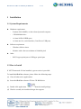
1 Installation
1.1 System Requirements
Hardware requirement
-
Pentium 586/166MHz, or above based personal computer
-
CD ROM disk drive
-
At least 10GB of HDD space
-
At least one free, serial interface (Com-Port or USB port)
Software requirement
-
Windows 2000 or above
-
Monitor with a fewest resolution of 600x800 pixel
Other
-
RS232 type optical port or USB type optical port
1.2 How to Install
If .NET Framework 2.0 has installed, a green version is provided.
To install this HexView software, please follow the following steps:
(a) Close all other active applications.
(b) Insert the HexView software CD into CD ROM drive
(c) Double click application
from the install package.
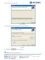
(d) Wait for seconds, the installer dialogue box appears.
HexView PC SW User Manual for HXE310
5 / 51
Start installation
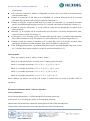
(e) Follow the instructions on the screen to progress the installation.
Selection
(f)
Click button
to the next interface.
NOTE: The default install disk drive is C.
HexView PC SW User Manual for HXE310
6 / 51
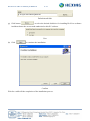
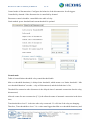
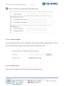
Default install disk
(g) Click button
to select the desired disk drive for installing HexView software.
And then choose the access mode authorized to this PC software.
User
(h) Click
to continue the installation.
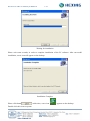
Confirm
Wait for a while till the completion of the installation process.
HexView PC SW User Manual for HXE310
7 / 51
Waiting for installation
Please wait some seconds, in order to complete installation of the PC software. After successful
installation, a new icon will appear on the desktop.
Installation Complete
Please click button
, at this time, a new icon
Double click this icon to operate.
appears on the desktop.
HexView PC SW User Manual for HXE310
8 / 51
2 HexView Basic
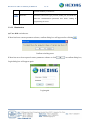
2.1 Login
Before start-up this HexView PC software, please ensure that the PC connection with the electricity
meter via optical probe. After successful installation, the new icon
will appears on the
desktop.
Double click shortcut
to login.
Login
Key in the User name and Password correctly, and then click button
to enter into the
main window.
NOTE: The default administrator ID is „Hexing‟ and default password is 000000. This user
is in the highest security level, which cannot be deleted and can change the password only by itself.
HexView PC SW User Manual for HXE310
9 / 51
3 Main Window Interface
3.1 Overview
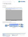
After logging in, the below interface appears. The interface is initial window interface.
Main window interface
The menu bar contains all the functions.
The main menu consists of Title bar, Menu bar and Icon bar.
Title bar
Menu bar
Icon bar
Main menu
HexView PC SW User Manual for HXE310
10 / 51
3.2 Functions of Menu
3.2.1 Menu Bar
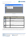
(a) File menu: In this menu there are 5 functions: New, Open, Save, Save as, And Exit.
File menu
File menu icon
Icon
Name
Purpose
New
Add establish meter parameter scheme
Open
Open the existing meter parameter schemes
Save
Save meter parameter scheme in default format
Save as
Save as meter parameters scheme
Exit
Exit HexView
NOTE: all these documents here are .dat files.
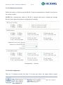
(b) System menu: In this menu there are 4 functions: User shift, Password change, User
HexView PC SW User Manual for HXE310
11 / 51
management, and Level access.
System menu
System menu icon
Icon
Name
Purpose
User shift
Registration User switchover
Password change
Change password, which is user‟s password. The users can change
their own passwords
User management
Add, edit or delete user account (Five levels of users are available.
User named Hexing is the supervisor and has the highest access
right who cannot be deleted), the user of level 1 has the right to
manage other users
Level access
Access Level, there are five levels totally. Level access defines
operation authority of each level
(c) Option: reference about communication, Parameters about meter type, protocol, media, port, and
baud rate, initial the communication parameters here before reading or programming the meter.
HexView PC SW User Manual for HXE310
12 / 51
Option menu
(d) Skin: there are more than 20 kinds of skin provided for HexView.
Skin menu
HexView PC SW User Manual for HXE310
13 / 51
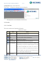
(e) Help menu: check version of HexView.
Click „About…‟ of Help menu, and appear the below dialog box.
This displayed the version information of the HexView.
3.2.2 Icon Bar
3.2.2.1 Icon Guide
The icon bar contains some frequently used functions.
Functions in icon bar
Icon
Name
Purpose
New
Add establish meter parameter scheme
Open
Open the existing meter parameter schemes
Save
Save meter parameter scheme in default format
User shift
Registration User switchover
Password change
Changes password, which is user‟s own password
User management
Add or delete user account (Five levels of users are available. User
named Hexing is the supervisor and has the highest access right
who cannot be deleted)Add, edit or delete user account (Five
levels of users are available. User named Hexing is the supervisor
and has the highest access right who cannot be deleted), the user
of level 1 has the right to manage other users
Level access
Access Level, there are five levels totally. Level access defines
HexView PC SW User Manual for HXE310
14 / 51
operation authority of each level
Reference
Parameters about meter type, protocol, media, port, and baud rate,
initial the communication parameters here before reading or
programming the meter
3.2.2.2 Illumination
(a) User shift: switch users.
If there has been a meter parameter scheme, confirm dialog box will appear after clicking
.
Confirm switching users
If there has never been opened a meter parameter scheme or click
Login dialog box will appear again.
Login again
in confirm dialog box,
HexView PC SW User Manual for HXE310
15 / 51
(b) Password change: change password of users.
Click shortcut
or „Password change‟ in system menu and pop up the below dialog box.
Password change
Change password setup
Name
Explanation
Username
Displays the name of current user
Old password
Inputs the old password of current user into this text box.
New password
Inputs the new password of current user into this text box
Confirm
Inputs the New password again to assure its right
OK
Saves amendment
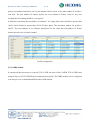
(c) User management: add ,edit or delete users.
Click „User management‟ to pop up the dialogue box as below, and you could get all kinds of work
of user information such as addition, modification done.
Add user: Key in the „Username‟ and „Password‟ , select specific security level for the user and
click „Add‟ button; then click „Save‟ to store the latest data. There are two authentication level:
HLS and LLS, HLS has the right to read and write the meter, but LLS only can read meter.
Program ID is reserved for future use.
Delete user: Select the user except „Hexing‟ in the user list, and click „Delete‟ button to delete it
and then deleted user will disappear in the user list.
HexView PC SW User Manual for HXE310
16 / 51
Edit user:Select the user in the user list, and click „Edit‟ button, and then you can change the
content in the blank of Password/Level. After editing, the information of the user list will be
refreshed.
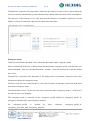
User management
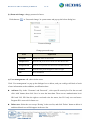
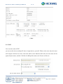
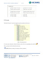
(d) Level access: define authorities for each level users.
There are 5 levels for users(3 levels for some meter type), and users in each level can have same or
different scope operations. The scope of each level can also be set by Level1.
For example, the below figure means that Level4 can have operations of Parameters, Energy,
Instantaneous values and Meter ID.
HexView PC SW User Manual for HXE310
17 / 51
Level access
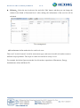
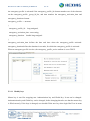
(e) Reference: Refer to meter types and communication parameter.
It can change communication parameter here, and be sure that the meter type and COM port are
correct before communication with meter. Make sure that no parameter scheme is opened before
changing the meter type. The threshold of over time is provided for you to modify when the
communication is not very good. Some meters support more than one protocol, for example
DLMS(Mode E) and DLMS(Direct HDLC for RS485), in HexView the default protocol is
DLMS(Mode E), if DLMS(Direct HDLC for RS485) is selected when communication, the
SubStation No. should be changed to four bytes, see detail information in chapter about option
.
HexView PC SW User Manual for HXE310
18 / 51
Reference
4 Main Communication Interface
4.1 Overview
4.1.1 Area Partition
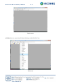
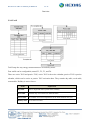
When adding a new file or open existing file, the main communication interface will appear:
HexView PC SW User Manual for HXE310
19 / 51
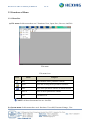
Main communication interface
This HexView, PC software, is major in configuration and readout data tool. Each tree node is
corresponding to relevant command. The main command is read, write and execute
their function
separately are data readout, parameter writing into and the execute operation.
The main window splits into main three parts of the main window.
Parts of main communication interface
Name
Location
Purpose
Main command area
The left area
It is major in main command selection
Data display area
The top right area
It is used for display readout data information
Communication state area
The bottom right area
It is designed for review communication state
4.1.2 Icons Menu
There are following icons available:
HexView PC SW User Manual for HXE310
20 / 51
Functions of icons menu
Icon
Name
Purpose
Option
Get knowledge of or change Sub station No. and password or AES key.
Read
Meter data readout
Write
Write parameters into meter
Disconnection
Disconnects communication
Save
Save parameters. The checked configurations will save to file(.set)
Open
Open the .set file to load the saved configurations.
Save as excel
Save data as excel format
Save as txt
Save data as txt file
Print
Print preview previous print
Save as PDF
Save data as PDF format
Clear
Delete the data of selected items ( the data are displayed in the Data
Display Area in HexView and not in Meter), and then the data becomes
default values.
NOTE: After clicking
No. and keys.
(Option), Meter Parameters will appear. See or change sub station
HexView PC SW User Manual for HXE310
21 / 51
Meter Parameters
Parameters
Name
Sub station No.
Explanation
Generally it is “01”, it is the logical address of meter.
If you is going to communicate with one meter, input the correct sub
station No. For protocol DLMS(Mode E) the length of sub station No.
is 1 byte, but for DLMS(Direct HDLC for RS 485) it is 4 bytes which is
the last 2 bytes of the meter serial number in the nameplate add „0001‟.
Authentication key
AES-GCM-128 is adopted for the security of information transfer.
Authentication key is part of additional authenticated data. The default
Authentication Key of the meter is 16 bytes of hex. HexView will not
save the keys, If the authentication Key of the meter is not the default
value(00 00 00 00 00 00 00 00 00 00 00 00 00 00 00 00), you should
input the correct authentication key here. It can be changed in menu
„Modify keys‟.
Global key
AES-GCM-128 is adopted for the security of information transfer.
Global key is the key for ciphering. The default Global Key of the meter
is 16 bytes of hex. HexView will not save the keys, If the global Key of
the meter is not the default value(00 00 00 00 00 00 00 00 00 00 00 00
00 00 00 00), you should input the correct authentication key here. It can
be changed in menu „Modify keys‟.
4.2 Parameters Operation Tools
Click symbol
in the left column, the relevant electronic values will be displayed.
Parameters operation tools on meter parameters scheme can separately operate option on the left, and
also operate multi-options or all the options depending on user‟s choice. User has chosen all the read
HexView PC SW User Manual for HXE310
22 / 51
operations and Basic parameters option of write operation, so that when click all the parameters of
these options will be read.
NOTE: HexView for different types of meters may contains some special parameter items, e.g.
for direct connection meter it do not contain CT/PT item.
Parameters operation tools
Functions of main command area
Name
Explanation
Purpose
Read
Readout
Reads data in meter
Write
Configuration
Sets data in meter
Execute
Executing
Executes especial operations in meter
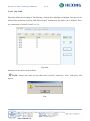
When clicking
, read all the selected parameters, and show and save the data readout. Symbol
stands for displayed items in display window.
HexView PC SW User Manual for HXE310
23 / 51
Selected item to display
When reading and writing, it will appear relevant communication information in the textbox at the
bottom of window, and error information will be marked with red. Click
information on the textbox, and click
on the right to save
to delete this information.
O
peration in communication state area
HexView PC SW User Manual for HXE310
24 / 51
5 Main Software Functions
5.1 Read
The Meter Read is used for readout the register data in the meter by HexView.
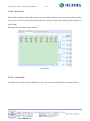
5.1.1 Parameters
Current parameters of the meter which are read only. Such as current tariff number, firmware
version.
Parameters
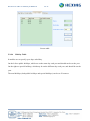
5.1.2 Energy
Current value of energy.
HexView PC SW User Manual for HXE310
25 / 51
Energy
5.1.3 Instantaneous Values
Instantaneous Values of meter, such as voltage, current, frequency, active power. For three phase, the
values are of every phase.
Instantaneous values
5.1.4 Billing data
Billing data, you can select all to read all billing data, also you can select the data range to read part
of billing data.
Billing data
HexView PC SW User Manual for HXE310
26 / 51
5.1.5 Profile
Read the profile log, there are 17 channels totally, the parameters of each channel can be modified in
menu „profile configuration‟. The records of a channel can be read out totally or partly.
Profile
5.1.6 Event
There are several types of event. You can choose reading some of them, also you can read the events
during a period of date.
Standard event log records all general events, e.g changes of the clock, changes of the configuration,
clearing of profiles, all kind of self check errors, activation of new parameters, activation of new time
of use, etc.
Fraud detection log records events related to fraud attemps, e.g removal of terminal cover, removal
of meter cover.
Disconnector control log records the events related to the disconnector, e.g connect, disconnect,
changing the disconnector threshold.
Grid event records the events related to power outages, low voltage, overvoltage, etc. Long power
failure log records the occurring time and duration of long power outages.
Long power outage event log records End of long power outage and Duration of long power
outages.
HexView PC SW User Manual for HXE310
27 / 51
Strong DC field records events about strong DC.
Meter cover removed records occurring time when meter cover removed.
Terminal cover removed records occurring time when terminal cover removed.
Current reverse records start and end of current reverse.
Program records the occurring time when program.
Power outage records the events about short power outage.
Recharge records the events about recharges.
Event
5.1.7 Error and alarm handling
A predefined selection of events set and clear flags in the error register. The error register can be read
and displayed at anytime to see, if there is a malfunction in the device. Depending on the type of
error, some errors clear themselves if the reason for the error has disappeared. Other must be cleared
via CAS. Nevertheless the events are stored in one of the event logs.
All alarm flags in the alarm register remain active until the alarm register is cleared via CAS
(acknowledgment). Typically fraud attempts are selected as alarm triggers. Typically fraud attempts
and critical errors are selected as alarm triggers. Power outages normally can't be selected since the
communication network is also down in case of a power outage.
HexView PC SW User Manual for HXE310
28 / 51
When some events such as power down, clock adjusted, daylight saving, data not valid, clock invalid
and critical error occur in E-meter, the corresponding bit of AMR profile status code will be set.
Error and alarm handling
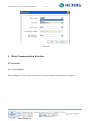
5.2 Write
The Meter Write is used for setting the parameters in the meter. Also the parameters to configure can
be read.
5.2.1 Meter ID
They are information about identification numbers. Here you can change the parameters about meter
location.
HexView PC SW User Manual for HXE310
29 / 51
Meter ID
5.2.2 Billing date
It is used to read and configure the closing date of billing period.
Click „Billing date‟ in main menu.
Format of Billing date is „dd hh‟ („date hour‟, dates are from 01 to 28 and hours are from 01 to 23),
and the default billing date is at 0 clock on 1st in each month.
Billing date
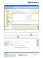
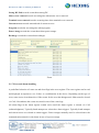
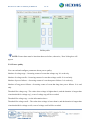
5.2.3 Display Configuration
Display items: it can set the contents displayed on the LCD and the scrolling interval between
previous and former items.
Display configuration
HexView PC SW User Manual for HXE310
30 / 51
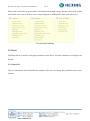
(a) Auto scroll display interval: set scrolling interval (unit:second).
Time & Format
(b) Auto scroll display items: get or set the contents displayed on the LCD in Auto scroll sequence.
(c) Manual display items: get or set the contents displayed on the LCD in manual scroll.
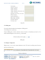
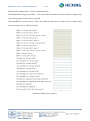
Make Auto scroll display items as an example:
1. Select the
before
read button
, and click
. Then click
to read the configurations in the meter first. The items that are already
configured in the meter will display in the left column.
2. Select
before items in the right column and click
. The selected items will display in
the left column.
3. If some items in the left column are considered unnecessary to display in auto scroll display
mode, select these items and click
or double click the selected item, they will be
removed from the display list.
4. Check if the display items list in the left column is correct. If there is no mistake, click
to write this configuration to the meter.
5. Repeat the first step to see if the items are successfully written to the meter.
HexView PC SW User Manual for HXE310
31 / 51
Add items displayed
Items setup
Name
Explanation
Auto scroll display interval
Set Scrolling interval [sec]. The range of it is from1s to 99s.
Auto scroll display items
Get or set the contents displayed on the LCD in Auto scroll
sequence in the meter
Manual display items
Get or set the contents displayed on the LCD in Manual scroll
sequence in the meter
Manual display items with
Get or set the contents displayed on the LCD in Manual display
security
items with security
NOTE: If need delete some items in Data Display Area, click
selected items, and then click
. Execute writing operation.
or double click the
HexView PC SW User Manual for HXE310
32 / 51
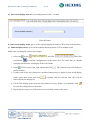
5.2.4 Communication interface
Define the interface of Optical port and RS-485. If optical communication is disabled, the baud rate
for it will be invalid.
NOTE:If the communication address of RS-485 is changed when meter communicates through
RS-485, please update the parameter configuration accordingly.
Communication
interface
5.2.5 Profile configuration
There are 17 channels provided (less than 17 for some type meter), the capture objects, capture
HexView PC SW User Manual for HXE310
33 / 51
period, start address and entries size of each channel can be read or write. Max number of records is
read only. The max number of capture objects for every channel is 9(item 1-item 9), any item
configured to be nothing should be “not specific”.
It should be noted that the start address of channel 1 for single phase meter should be greater than
16476, and it should be greater than 22134 for three phase. The maximum address for profile is
540671. The start address of one channel should not less the value that start address of former
channel plus the size of former channel.
Profile configuration
5.2.6 GPRS module
It contains all data necessary to set up the TCP or UDP sub-layer of the COSEM TCP or UDP based
transport layer of a TCP-UDP/IP based communication profile. The GPRS module can be configured
to be always on or on demand and PDP valid or PDP invalid.
HexView PC SW User Manual for HXE310
34 / 51
GPRS
5.2.7 RTC
Get or set the value of RTC.
you can set the time according PC time or input time by yourself. When set the new time, the meter
will compare with the new time, if the time shift is more than the limit value, the new time will be
ignored by the meter, and the CAD bit of AMR profile status code E meter will be set.
HexView PC SW User Manual for HXE310
35 / 51
Date/time
5.2.8 Tariff
Tariff setup the way energy measurements are recorded by meter.
Four tariffs can be configurable, named T1, T2, T3, and T4.
There are active TOU and passive TOU, active TOU is the active calendar, passive TOU is passive
calendar, which can be active at passive TOU activation date. They contain day table, week table,
season table. Holiday is active forever.
Name
Explanation
Day table
Sets to begin and end at specific times each day
Week table
Defines days of week that use different tariffs
Season table
Is available for seasonal adjustments to the tariff schedule each year
Holiday table
Is used for occasions
HexView PC SW User Manual for HXE310
36 / 51
5.2.8.1 Day Table
Day table define the switching of Tariff during a 24 hour day, midnight to midnight. Each day can be
divided into maximum 8 periods with different tariff. Maximum 4 day tables can be defined. There
are a maximum of 4 tariffs, from T1 to T4.
Day table
Maximum 8 day tables can be defined.
NOTE: Former time must be later than time set before, otherwise, „Note‟ dialog box will
appear.
Note
HexView PC SW User Manual for HXE310
37 / 51
5.2.8.2 Week Table
Week table configures which Day table occurs by default each day of the week. Day table selection
is for every day of a week. Select the Day table for each day of the week using the drop down boxes
on the right.
Maximum 4 week tables can be defined.
Week table
5.2.8.3 Season Table
It enables user to define tariff in different season. One year can be divided into 4 seasons at most.
HexView PC SW User Manual for HXE310
38 / 51
Season table
5.2.8.4
Holiday Table
It enables user to specify up to days as holiday.
On the left are public holidays, which are on the same day each year and should not be set the year.
On the right are special holidays, which may be on the different day each year, and should be set the
year.
The total holidays (both public holidays and special holidays) can be set 50 at most.
HexView PC SW User Manual for HXE310
39 / 51
Holiday table
NOTE: Former date must be later than dates set before; otherwise, „Note‟ dialog box will
appear.
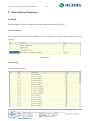
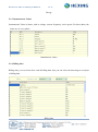
5.2.9 Power quality
You can read and configure parameters about power quality.
Number of voltage sags—Occurring counts of event that voltage sag. It is read only.
Number of voltage swells-- Occurring counts of event that voltage swells. It is read only.
Number of power failures—Occurring counts of event that power failures. It is read only.
Number of long power failures—Occurring counts of event that long time power failures. It is read
only.
Threshold for voltage sag—The value when voltage is higher than it, and the duration is longer than
„time threshold for voltage sag‟, event of voltage sag will be recorded.
Threshold for voltage sag—see the information above.
Threshold for voltage swell—The value when voltage is lower than it, and the duration is longer than
„time threshold for voltage swell, event of voltage swell will be recorded.
HexView PC SW User Manual for HXE310
40 / 51
Threshold for voltage swell—see the information above.
Time threshold for long power failure—The value which the duration of power failure is longer than,
event of long power failure will be recorded.
Time threshold for current reverse—The value which the duration of current reverse is longer than,
event of current reverse will be recorded.
Parameters about power quality 1
HexView PC SW User Manual for HXE310
41 / 51
Parameters about power quality 2
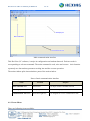
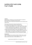
5.2.10
Disconnector
You can get the output state, control mode,control state , the limiter threshold of disconnector and
information of emergency profile,
also the control mode of disconnector and emergency profile can
be configured. Output state shows the actual physical state of the disconnect unit, i.e. if an electricity
breaker or a gas valve is open or closed, the state is „connected‟ or „disconnected‟. Control state
shows the internal state of the disconnect control object, the state is „disconnected‟, „connected‟ or
„ready for reconnection‟. Control mode configures the behavior of the disconnect control object for
all triggers, the possible state transitions are Mode 0 (None. The disconnect control object is always
in „connected‟ state) ,
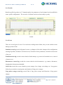
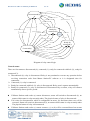
Control Logic
HexView PC SW User Manual for HXE310
42 / 51
Disconnected(0)
(a)remote disconnect
(d)Reconnect time over
(b)Disconnect time over
(b)Disconnect time over
(a)remote disconnect
(c)remote connect
(i)Reconnect time over
Ready for
connected(2)
(b)Disconnect time over
(a)remote disconnect
(h)remote connect
E overtime
Flag
(e)Manual reconnect
(j)N overtime
(h)remote connect
(l)E overtime
(i)Reconnect time over
(g)Manual disconnect
Ready for
connected(3)
(m)E to N
Connected(1)
(h)remote connect
(i)Reconnect time over
(e)Manual reconnect
(k)auto reconnect
(f)overload disconnect
(n)cancel overload control
Diagram of relay control logic
Control status:
There are four statuses: disconnected (0), connected (1), ready for connected with lock (2), ready for
connected (3).
Disconnected (0): relay is disconnected. Relay is not permitted to execute any operation before
receiving connection order from Master Station/PC software or it is designated time for
connection.
Connected (1): relay is connected.
Ready for connected with lock (2): relay is disconnected. Relay won‟t connect automatically.
Ready for connected (3): relay is disconnected. Disconnected by overflow, relay will connect
automatically after a specific period.
If Master Station sends order (a) remote disconnect, status will switch to disconnected (0), no
matter which status is relay currently under. The physical status of relay is disconnected.
If it is time for disconnection, which is configurable on meter, (b) disconnect time over will be
executed. Status will switch to disconnected (0), no matter which status is relay currently under.
The physical status of relay is disconnected.
If Master Station sends order (c) remote connect, (c) or (h) will be executed based on current
HexView PC SW User Manual for HXE310
43 / 51
control mode.
If it is time for connection, which is configurable on meter, (d) or (i) will be executed based on
current control mode.
If status is connected (1) and load is over threshold, (f) overload disconnect will be executed
automatically and status will switch to ready for connected (3).
If status is ready for connected with lock (2) or ready for connected (3), (e) manual reconnect
can be executed through long press on key for 3 seconds, and status will switch to connect (1).
If status is ready for connected (3), it can switch to connected (1) through the execution of (k)
auto reconnect.
Generally, (j) N overtime will be executed after specific times of overflow disconnection, then,
status switches to ready for connect (2).
In emergency, (1) E overtime will be executed after specific times of overflow disconnection,
then, status switches to ready for connect (2), at the same time, E overtime flag will be set.
If status is ready for connect (2) and there is E overtime flag, (m) E to N will be executed, when
emergency switches to normal situation, then, status switches to connected (1).
If the working mode permits, (g) manual disconnect can be executed through long press on key
for 3 seconds, then, status switches to ready for connected with lock (2).
Control mode:
There are 4 modes: mode 0, mode1, mode 2, mode 3.
Mode 0: no operation can be executed, meter is under protection mode.
Mode 1: executable operations: a / b / c / d / e / f / g / j/ k / l / m / n
Mode 2: executable operations: a / b / e / f / g / h / i / j/ k / l / m / n
Mode 3: executable operations: a / b / c / d / e / f / j/ k / l / m / n
Mode 4: executable operations: a / b / e / f / h / i / j/ k / l / m / n
Power utilities can choose one of the four modes or switch from one mode to another while in
operation.
Parameters Definition On PC Software Interface:
Active parameters:
Active limiter threshold(A): overflow threshold of currently used relay
Active mode: it is in Emergency mode or Normal mode currently
Output state of disconnection: shows the actual physical state of the disconnection.
Control state of disconnection: shows the internal state of the disconnection
HexView PC SW User Manual for HXE310
44 / 51
Control mode of disconnection: Configures the behavior of the disconnection for all triggers.
Controlled by demand: if the disconnection is controlled by demand
Disconnect control scheduler: controllable time table of relay
Limit method: power threshold and current threshold is optional.
Normal mode
Table of normal limiter threshold: relay control threshold table
Min over threshold duration(s) is delayed time threshold, which means over limiter threshold “ Min
over threshold duration” seconds,relay will disconnected; and the default time is 30s;
Threshold for connection after disconnect is the delayed time of automatic connection after the relay
disconnected;
Allowed counts for auto reconnection [C1] is the allowed counts of automatic connection in the short
time;
Time threshold to clear C1 is the time after relay connected. C1 will clear if the relay no changing.
Therefore, Time threshold to clear C1 is a value must bigger than Min over threshold duration(s) and
HexView PC SW User Manual for HXE310
45 / 51
Threshold for connection after disconnect, otherwise the number of times will be cleared when the
relay not connects automatically yet after disconnection, and the allowed counts will be meaningless.
The objective of this function is let relay possesses the function of automatic connection, but the
number of times of connection cannot be too much in the short time.
Emergency mode
Table of normal limiter threshold: relay control threshold table under emergency mode
Min over threshold duration(s) is delayed time threshold under emergency mode, which means over
limiter threshold “ Min over threshold duration” seconds,relay will disconnected, and the default
time is 30s;
Threshold for connection after disconnect is the delayed time of automatic connection after relay
disconnected under the emergency mode;
Allowed counts for auto reconnection[C1] is the allowed counts of automatic connection in the short
time under emergency mode;
Time threshold to clear C1 is the time after relay connection under emergency mode; C1 will clear if
the state of relay is no changing.
The emergency mode is activated via the emergency profile defined by emergency profile id,
emergency activation time, and emergency duration.
An
emergency_profile
is
defined
by
emergency_activation_time, emergency_duration.
three
elements:
emergency_profile_id,
HexView PC SW User Manual for HXE310
46 / 51
An emergency profile is activated if the emergency_profile_id element matches one of the elements
on the emergency_profile _group_id_list, and time matches the emergency_activation_time and
emergency_duration element:
emergency_profile ::= structure
{
emergency_profile_id:
long-unsigned,
emergency_activation_time: octet-string,
emergency_duration:
double-long-unsigned
}
emergency_activation_time defines the date and time when the emergency_profile activated.
emergency_duration defines the duration in seconds, for which the emergency_profile is activated.
When an emergency profile is active, the emergency_profile_active attribute is set to TRUE.
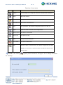
5.2.11
Modify keys
Master key is used for wrapping new Authentication key and Global key. It can not be changed.
Authentication key and Global key can be changed, before changing them be sure that the master key
is filled correctly. If the keys is changed, user should fill the new key when login HexView in menu
HexView PC SW User Manual for HXE310
47 / 51
. The keys will always be default value after login HexView.
5.2.12
Firmware upgrade
The new image will not be active immediately after firmware update communication, it will be
active at activation time. Image version is the version of image wait to active.
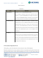
5.2.13
Function switch
If the set item is invalid, the meter will not record corresponding event.
HexView PC SW User Manual for HXE310
48 / 51
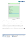
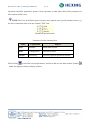
5.3 Execute
The Meter Execute is used for setting the special operations in the meter.
Meter Executing System
If execute some functions, click the Checkbox on the left of corresponding items, and click
These operations will be finished in the meter.
NOTE: When executing, be cautious of these operations.
.
HexView PC SW User Manual for HXE310
49 / 51
NOTE: Due to continuous improvement of the software, the screenshot shown in this user
manual might be slightly different with the actual software interface. Information in this document is
subject to change without notice. The information is accurate at the time of printing (March, 2013)
© Hexing Electrical
HexView PC SW User Manual for HXE310
50 / 51
Hexing Electrical
Add: Shangcheng Industrial Zone, 1418 Moganshan Rd, Hangzhou, China
TEL: +86-571-28020767/769
FAX: +86-571-28029263
www.hxgroup.cn
[email protected]