1
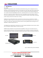
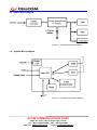
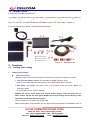
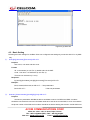
miniBee User Manual V2.1 Your Best Choice For Security & Fleet Management ※This product can only use in fleet management, please do not use in illegal propose. ※To decrease electromagnetic wave harm from human body, please use in well-arranged. ACOM COMMUNICATIONS CORP. 6B16, No. 5, Sec. 5 Xin Yi Road, Taipei, Taiwan TEL : 886-2-27588663 (REP.), FAX. : 886-2-27202442, Web site : www.cellcom.tw Email: [email protected] Contents 1. 2. 3. 4. INTRODUCTION ..................................................................................................................................................... 3 1.1. INTRO .................................................................................................................................................................. 3 1.2. SPECIFICATIONS ................................................................................................................................................... 4 1.3. POWER BLOCK DIAGRAM ..................................................................................................................................... 5 1.4. SYSTEM BLOCK DIAGRAM .................................................................................................................................... 5 1.5. PACKAGE CONTENT ............................................................................................................................................. 6 FUNCTIONS............................................................................................................................................................. 6 2.1. TRACKING AND LOCATING ................................................................................................................................... 6 2.2. SECURITY AND ANTI-THEFT ................................................................................................................................. 7 2.3. DATA LOG AND UPGRADE .................................................................................................................................... 8 INSTALLATION........................................................................................................................................................ 9 3.1. INDICATOR AND SOCKET ...................................................................................................................................... 9 3.2. INSTALL SIM CARD ............................................................................................................................................ 10 3.3. INSTALL GSM ANTENNA ................................................................................................................................... 11 3.4. INSTALL GPS ANTENNA .................................................................................................................................... 11 3.5. INSTALL 8 PIN CABLE.......................................................................................................................................... 11 3.6. WIRE CHART ...................................................................................................................................................... 12 CONFIGURATION ................................................................................................................................................ 12 4.1. CONNECT WITH CONNECT CABLE ...................................................................................................................... 12 4.2. USE WINDOWS BUILD-IN PROGRAM TO CONFIGURE ......................................................................................... 13 4.3. BASIC SETTING .................................................................................................................................................. 15 4.4. ELECTRICITY SAFETY USE CONVENTIONS ........................................................................................................... 17 ACOM COMMUNICATIONS CORP. 6B16, No. 5, Sec. 5 Xin Yi Road, Taipei, Taiwan TEL : 886-2-27588663 (REP.), FAX. : 886-2-27202442, Web site : www.cellcom.tw Email: [email protected] 1. Introduction 1.1. Intro MiniBee is a new generation of AVL announced by Helioversal Technology, which is designed for security applications and fleet management purposes. It has smaller size in L85 x W56 x H20 mm than other products on the market and very light weight in only 120g. This device is employed with all industrial standard parts, such as Ublox LEON-G100 GSM/GPRS module, with 4 quad-band rate which can provide more widely use in globe. Also, accept Ublox module in GPS function, which named AMY-5M, with premier ability in fast and accurate unit positioning. Moreover, A-GPS function is also build in this module, which provides more speedy position locating in about few seconds when in booting. MiniBee has many similar features to M1, such as both of two may let user give commands or configure parameters via SMS or online server from GPRS, both of two have most 32000 data save memory and can be log out in any minute. Also, build with the common functions in security between both with towing alert, over speed alert, 10 GEO-Fencing function, etc. The MiniBee has 6 configurable I/O. Unlike with M1, it can be configure with different mounts of input or output ports, even digital or analog, depend on actual use to clients. MiniBee has been defined as a strong functional but acceptable for newly user. As the reason it have no employ with RS232 serial port for connect with accessories, which can provide to customer for lower prices. With those superiority, we believe that MiniBee will be the best choose for clients in purchase an AVL devices.. Top View Side View Front View 45 Degrees View Figure 1.Different views pictures of MiniBee ACOM COMMUNICATIONS CORP. 6B16, No. 5, Sec. 5 Xin Yi Road, Taipei, Taiwan TEL : 886-2-27588663 (REP.), FAX. : 886-2-27202442, Web site : www.cellcom.tw Email: [email protected] 1.2. specifications Size and Weight Size (L x W x H) 85 x 56 x 20mm (without external antenna) Weight 120 g (Include internal battery) Power Volt range DC 9V to 36V Power consumption (Internal battery full state) Idle 30mA @DC 12V GPS working 43mA@DC 12V GSM/GPS Working 70mA@DC12V Max. 500mA @DC 12V ([email protected]) Open collector output rate Max A: 250mA Max V: DC60V Battery Li-ion chargeable battery 1000mAH Working Temperature -30 ℃ to 85℃ I/O Port mount Digital Input 4 Analog Input 1 Output 1 GSM Module Model name U-blox LEON-G100 GSM module Band and consumption rate GSM 850/900/1800/1900MHz class 4 (2W) for EGSM 850/900 class 1 (1W) for GSM 1800/1900 SIM card interface Supports 1.8V and 3V GPRS mode Class10 GSM antenna External GPS Module Model name U-blox 5 GPS receiver AMY-5M Receiver 50-channel u-blox5 engine GPS L1 C/A code SBAS: WAAS,EGNOS,MSAS,GAGAN Accuracy Normal 2.5mCEP By SBAS AGPS Exist GPS antenna External 2.0m CEP Chart1.2 miniBee specifications ACOM COMMUNICATIONS CORP. 6B16, No. 5, Sec. 5 Xin Yi Road, Taipei, Taiwan TEL : 886-2-27588663 (REP.), FAX. : 886-2-27202442, Web site : www.cellcom.tw Email: [email protected] 1.3. Power Block diagram Figure1.3 miniBee Power block diagram 1.4. System Block diagram Figure1.4 miniBee System Block diagram ACOM COMMUNICATIONS CORP. 6B16, No. 5, Sec. 5 Xin Yi Road, Taipei, Taiwan TEL : 886-2-27588663 (REP.), FAX. : 886-2-27202442, Web site : www.cellcom.tw Email: [email protected] 1.5. Package Content In a package of miniBee it should have: 1 miniBee x1○ 2 Connect cable x1○ 3 8 pins cable x1○ 4 GSM antenna x1○ 5 GPS antenna x1○ 6 SIM card ○ 7 Y pinx3○ 8 wire cilpx3○ 9 cable ties x3○ 10 Reserve fuse x1○ 11 Velcro (Male + Female) x1 trayx1○ If you find anything short, please contact with Helioversal agent. 5 ○ 1 ○ 錯 6 ○ 11 ○ 錯 錯 2 ○ 錯 錯 4 ○ 錯 7 ○ 錯 10 ○ 錯 3 ○ 錯 9 ○ 錯 8 ○ 錯 Figure 1.5 Package content 2. Functions 2.1. Tracking and Locating 1. Tracking and Locating Real Time Tracking: MiniBee is able to send real time location information to the server with SMS or via GPRS. ¾ Communication Mode: MiniBee can send data via GPRS or SMS to server. System can be auto-resend the data when in unsuccessful transmission via GPRS. ¾ AVL States: The MiniBee can work in one of three states, which are Online, Offline and Emergency mode. On Line means Acc on, system operating MiniBee will turn to online mode when vehicle engine ignition circuit has been turn on. When vehicle achieve the limit speed, MiniBee will start recording vehicle traveling route, speed and current state data into memory. Off Line means Acc off, system turn to idle mode When vehicle ignition circuit has been turn off, after an interval time passed, the MiniBee will turn to ACOM COMMUNICATIONS CORP. 6B16, No. 5, Sec. 5 Xin Yi Road, Taipei, Taiwan TEL : 886-2-27588663 (REP.), FAX. : 886-2-27202442, Web site : www.cellcom.tw Email: [email protected] offline mode. All of the MiniBee anti-theft functions activate at offline mode, including intrusion alert, unauthorized start, towing alert etc. Also, system still transmits data with unit IP and name in offline mode time interval. Emergency means Panic button has been pressed. When panic button has been pressed, it will turn to emergency mode and keep transmit current location data to owner and server until owner or server send disarm command. ¾ Time Interval configurable: On Line, Off Line and Emergency time intervals are pre-settable, the time interval range is from 5 to 9999 seconds. MiniBee sends data to server periodically according to the corresponding time interval. Query Position: Both vehicle owner and server are able to make a phone call to MiniBee to query the current position. ¾ MiniBee only response for 3 pre-specified mobile phones. ¾ MiniBee will to send the location information when user dialing to system phone number and hang up the phone after 1 ring. The system will send current location data to server or reference phone numbers. ¾ Users can also query unit current position by sending SMS or command with a string $ ping, system will feed back information. Accumulation Mileage: MiniBee is able to accumulate the journey distance while Acc is on. ¾ The mileage will show in 13th section of data strings and transmit to server. ¾ The Journey distance is calculated every second during Acc on and updates every 1km. ¾ A Journey end event occurs while Acc is turned off. ¾ The accumulation mileage value can be clear by sending command via GPRS. Geo Fencing: MiniBee can monitor 10 areas as geo-fence simultaneously and sends alert message to server as well as SMS to 3 designated mobile phones while vehicle is entering or exiting any geo-fence. ¾ 10 Geo-Fence can be set. ¾ Output 1 can be activated while vehicle is entering and exiting any geo-fence. ¾ MiniBee sends SMS to 3 designated mobile phones and alert message to server via PRGS while vehicle is entering and exiting any geo-fence. ¾ Output 2 can be activated when vehicle enters the Geo-Fence, while Output 2 can be inactivated when vehicle exits the Geo-Fence ¾ Once output 1 is activated, it can not recover automatically. Output 1 should be reset manually by sending a command to MiniBee with SMS or by server via GPRS to release the output 1. 2.2. Security and Anti-theft ACOM COMMUNICATIONS CORP. 6B16, No. 5, Sec. 5 Xin Yi Road, Taipei, Taiwan TEL : 886-2-27588663 (REP.), FAX. : 886-2-27202442, Web site : www.cellcom.tw Email: [email protected] Event Notification: MiniBee is able to send SMS to 3 designated mobile phones and command to server via GPRS in the following cases. ¾ Alert cases: Panic: Panic button has been pressed. Intrusion alert: Intrusion detect sensor has been activating under armed state.. Unauthorized start: Vehicle engine has been turned on under armed state Entering Geo-Fence. Exiting Geo-Fence. External power losing: AVL lost regular power supply. (When external voltage downs to 4.7 volts). Low power of Backup Battery AVL internal battery power exhausted or breakdown (when backup battery voltage downs to 3.5 volts). In above case MiniBee will send SMS to reference phone number and data to server until alarm disarm or internal power exhausted. Towing Alert: MiniBee sends alert message to server and send SMS to 3 designated mobile phones when ACC is off and vehicle has been moved more than a distance away from the original parking place. ¾ Towing-Alert function is activated automatically when in offline mode. ¾ MiniBee will transmit alert message to server via GPRS and sends alert message to designated phone numbers with SMS. Over Speed Alert: MiniBee can monitor the speed all the time and create a event when speed is over preset value. ¾ Speed over value is pre-settable. ¾ Over speed keeping time is pre-settable. ¾ When speed has been over for a predefined time, MiniBee sends an alert message to server via GPRS and 3 SMS to 3 designated mobile phones. ¾ A buzzer can be installed to output2 to alarming driver locally. Immobilization: MiniBee is able to have vehicle to stop anytime by server via GPRS or SMS.. ¾ Manual-break ignition circuit or electricity of fuel pump: Both server and owner of the vehicle are able to have outputs changing state immediately to stop the vehicle. An output command can be sent via GPRS by server or with SMS by owner. 2.3. Data Log and Upgrade Historical Path Data Log: MiniBee has a large capacity memory for saving historical path data. ¾ The maximum records can be saved in the memory is 32,767. In case MiniBee writes location data every 30 seconds (twice per minute) to memory, and 8 working hours per day, then the total ACOM COMMUNICATIONS CORP. 6B16, No. 5, Sec. 5 Xin Yi Road, Taipei, Taiwan TEL : 886-2-27588663 (REP.), FAX. : 886-2-27202442, Web site : www.cellcom.tw Email: [email protected] days, that the records can be saved, is calculated as follows: 32000÷2÷60÷8 = 34(days). ¾ It will overwrite data every time when memory is full, therefore there will keep the last 32,767 records in the memory.. Data Dump: Historical path log data and can be downloaded by server via GPRS anytime. ¾ Starting date time and ending date time are specifiable. ¾ Dumping procedure can be interrupt in anytime. ¾ Records in the memory are able to be cleared with clear command from server. Upgrade program On The Air (OTA): MiniBee is possible to upgrade firmware via GPRS by server on the air that means vehicles does not need to go back the base for firmware upgrade but do so by any time and any where they are. ¾ Vehicle has no necessary to be driven back to garage. ¾ Client has no necessary to sent back MiniBee to manufacturer for upgrade program. Remote Control: Two remote control modes are available in MiniBee as follows. ¾ Mobile Phone: User is able to use there own mobile phone to set the outputs of the MiniBee. ¾ Server: The outputs of the MiniBee are able to be set or reset by server with commands directly. Open Protocol for Integration: The protocol for communicating between server and MiniBee is opened for System Integrator to integrate the protocol of MiniBee into their existing platform. 3. Installation 3.1. Indicator and socket Rear View 1 ○ 2 ○ 錯 錯 3 ○ 錯 錯 4 ○ 10 ○ 7 ○ 8 ○ 9 ○ 11 ○ 錯 5 ○ Front View 錯 錯 錯 錯 6 ○ 錯 錯 12 ○ Figure2.2 miniBee indicators and sockets ACOM COMMUNICATIONS CORP. 6B16, No. 5, Sec. 5 Xin Yi Road, Taipei, Taiwan TEL : 886-2-27588663 (REP.), FAX. : 886-2-27202442, Web site : www.cellcom.tw Email: [email protected] 1 8 Pin cable socket ○ 2 miniBee to PC connect cable socket ○ 3 Helioversal official engineering socket (no available to client) ○ 4 ○ Force shutdown button 5 GPS antenna terminal ○ 6 GSM antenna terminal ○ 7 Status indicator: Red light flashing if miniBee running data transmitting. Or keep lighting. ○ 8 Charge indicator: Red light lighting if MiniBee internal battery charging or extinguish. ○ 9 GPS indicator: Orange GPS indicator flashing for locating successfully, or keep lighting. ○ 10 ○ GSM indicator: Orange GSM indicator flashing for connecting to base successfully, keep lighting when data transmitting. 11 ○ Power indicator: Blue Indicator lighting If use external power source, if external power source cut off and switch to internal battery, it will flashing. 12 ○ SIM card socket: Insert SIM card with tray in here. 3.2. Install SIM card Put the SIM card on the tray which attach in package and insert to socket as figure shows. ACOM COMMUNICATIONS CORP. 6B16, No. 5, Sec. 5 Xin Yi Road, Taipei, Taiwan TEL : 886-2-27588663 (REP.), FAX. : 886-2-27202442, Web site : www.cellcom.tw Email: [email protected] Figure3.1 Install SIM card 3.3. Install GSM Antenna Install the GSM antenna to the terminal with “GSM Ant.” words. Figure3.3 Install GSM Antenna 3.4. Install GPS Antenna Install the GPS antenna to the terminal with “GPS Ant.” words. Figure3.4 Install GPS Antenna 3.5. Install 8 Pin cable Install each wire to each terminal in vehicle, then insert the plug in socket with ”Power & I/O” words, as figure shows.。 ACOM COMMUNICATIONS CORP. 6B16, No. 5, Sec. 5 Xin Yi Road, Taipei, Taiwan TEL : 886-2-27588663 (REP.), FAX. : 886-2-27202442, Web site : www.cellcom.tw Email: [email protected] Find each correspond terminal on vehicle. Figure3.5 Install 8 pin cable 3.6. Wire Chart 1 ○ 2 ○ 3 ○ 4 ○ 錯 錯 錯 錯 Numbers in 〇 means Pin number (Figure shows from plug way) 5 ○ 6 ○ 7 ○ 8 ○ 錯 錯 錯 錯 PIN COLOR FUNCTION MULTI-FUNCTION Pin1 Red █ Power Source Pin2 Black █ Ground Pin3 Orange █ ACC ACC Pin4 Gray █ Input1 Input1(positive)/Aanalog Input 1 Pin5 Purple █ Analog Input2(positive)/ Aanalog Input 2 Pin6 Green █ SOS Input3(nagtive)/Output 1 Pin7 Brown █ Input2 Input4(positive) Pin8 Yellow █ Output Input5(nagtive)/Output 2 Figure3.6 Wire Chart 4. Configuration 4.1. Connect with Connect cable Use the cable to link to computer, as figure shows. ACOM COMMUNICATIONS CORP. 6B16, No. 5, Sec. 5 Xin Yi Road, Taipei, Taiwan TEL : 886-2-27588663 (REP.), FAX. : 886-2-27202442, Web site : www.cellcom.tw Email: [email protected] Link to computer by USB port Figure4.1 Connect with Connect cable 4.2. Use Windows build-in program to configure We can use program which build in Windows to configure the MiniBee. Here’s example in XP: ( Vista & Windows 7 need to download by own self or use another program such as putty to done the task.) 1. Start→All Programs→Accessories→Communicate→Hyper Terminal 2. Named this connection as figure shows: M1 parameter setting Figure4.2.(2) Named this connection 3. Select the COM Port connecting with MiniBee: ACOM COMMUNICATIONS CORP. 6B16, No. 5, Sec. 5 Xin Yi Road, Taipei, Taiwan TEL : 886-2-27588663 (REP.), FAX. : 886-2-27202442, Web site : www.cellcom.tw Email: [email protected] M1 parameter setting Figure4.2.(3) Select the COM Port 4. Set the baud rate to 38400 and configure with other setting then click “OK”. 38400 Figure4.2.(4) Set baud rate 5. Now we can start use. The basic setting of miniBee please refer to chapter 4.3. When use this program to configure, beware always key in the right command once a second, press “enter” key to send the command, if input successfully it will reply the current parameter of command, or it will show “error command” as figure. ACOM COMMUNICATIONS CORP. 6B16, No. 5, Sec. 5 Xin Yi Road, Taipei, Taiwan TEL : 886-2-27588663 (REP.), FAX. : 886-2-27202442, Web site : www.cellcom.tw Email: [email protected] Figure4.2.(5) Start Use 4.3. Basic Setting Following are basic settings for miniBee. Client can configure those settings by connection with PC or by SMS way. (1). $unit,[ID],[Unit name],[Time zone]<CR><LF> Purpose: sets unit id, unit name and time zone. Format: ID: 15 characters (0~9,A~Z,a~z), default value is the IMEI Code: Unit name: 15 characters (0~9,A~Z,a~z). Time zone: 6 characters (+/-xx:xx). Response: $,[Unit ID],[Unit Name],unit,[ID],[Unit name],[Time zone]<CR><LF> Example: $unit,123456,helioversal,+8<CR><LF> // Set parameters $unit<CR><LF> (2). // Get unit parameters $server1,[Phone Number],[On/Off],[IP],[Port]<CR><LF> Purpose: Set server1 parameters. MiniBee is able to send data to server via GPRS and SMS. A modem should be connected to the server if GPS data needs to be sent to server with SMS, in such circumstance the phone number of the SIM card in modem should be set before starting this function. On/Off field is set ACOM COMMUNICATIONS CORP. 6B16, No. 5, Sec. 5 Xin Yi Road, Taipei, Taiwan TEL : 886-2-27588663 (REP.), FAX. : 886-2-27202442, Web site : www.cellcom.tw Email: [email protected] or reset to enable or disable the unit connecting to server1. IP and Port are the IP address and port number of the server1. Format: Phone Number: 20 characters (‘+’,0~9). On/Off: 1 character (0:Off, 1:On). IP: 15 characters (xxx.xxx.xxx.xxx). Port: 6 digit characters (0~65535). Response: $,[Unit ID],[Unit Name],server1,[Phone Number],[On/Off], [IP],[Port]<CR><LF> Example: $server1,,1,123.210.12.134,1000<CR><LF> // Set the IP and Port of Server1. (3). $gprstrk,[On/Off],[Online Time Interval],[Offline Time Interval],[Emergency Time Interval][Report Times]<CR><LF> Purpose: Set GPRS tracking parameters. On/Off field is set or reset to enable or disable the GPRS tracking function. Online Time Interval is the periodic time to send data to server from MiniBee when ACC is on. Offline Time Interval is the periodic time to send data to server from MiniBee when ACC is off. Emergency Time Interval is the periodic time to send data to server from MiniBee when panic button is pressed, no matter ACC is on or off. Report Times should be set to 0 when working in Time Tracking mode; While Report Times is not 0 which is working on Tracking On Demand mode, in this mode MiniBee is waked up to send data when user or server make a phone call to MiniBee, the Report Times parameter is the times that MiniBee sends location data to server. Format: Online Time Interval: (5~9999) Second Offline Time Interval: (5~9999) Second Emergency Time Interval: (5~9999) Second Report Times: (0,1~9999) times Response: $,[Unit ID],[Unit Name],gprstrk,[On/Off],[Online Time Interval], [Offline Time Interval], [Emergency Time Interval],[Report Times] <CR><LF> Examples: $gprstrk,1,30,120,10,0<CR><LF> $gprstrk,0,,,,3<CR><LF> //Time Tracking mode //Tracking on demand mode ※Below are basic setting command for miniBee, the full commands please find the ”miniBee Protocol Manual”. ACOM COMMUNICATIONS CORP. 6B16, No. 5, Sec. 5 Xin Yi Road, Taipei, Taiwan TEL : 886-2-27588663 (REP.), FAX. : 886-2-27202442, Web site : www.cellcom.tw Email: [email protected] 4.4. Electricity Safety Use Conventions 1. When supply power to miniBee, please follow the power consumption range described in chapter 1.2. Over or lower level will cost AVL damage and short the service life. 2. Please use the national qualified power supplier. Client will respond for themselves for damage cause from use unqualified power supplier. 3. Do not dismantle miniBee by yourself, if there has any damage please contact Helioversal agent for service. 4. Avoid to put miinBee in state over -30 ℃ and 85℃ range, also keep out from heat and any liquid. 5. Once you don’t need this product anymore, do not discard them with normal waste. Please find a qualified waste electronic products processor to help you. If you have any question please contact to Helioversal service agent. ACOM COMMUNICATIONS CORP. 6B16, No. 5, Sec. 5 Xin Yi Road, Taipei, Taiwan TEL : 886-2-27588663 (REP.), FAX. : 886-2-27202442, Web site : www.cellcom.tw Email: [email protected]