1
21
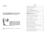
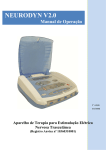
1- On-OFF key.
2- Light Indicator (green) of ON condition.
3- Fuse rack.
4- Power cable port to be connected to the power supply line.
5- Alphanumerical liquid crystal DISPLAY
6- START/STOP control keys
7- BACK/NEXT keys. SET+ and SET - control keys.
8- Control key PROGRAM/MENU
9- Current intensity control keys of CHANNEL 1 to CHANNEL 10. Each channel has a luminous
yellow indicator. This luminous indicator (yellow) indicates the presence of an output area
that can deliver a tension higher than 10 Volts or a current higher than 10 mA to a charge
resistance of 1000 ohms. After programming the equipment and pressing the START key, as
long as the equipment is connected in CONT. (continuous) stimulation mode, this indicator
will remain continuously on. When the stimulation mode for SYNC. or ALT. (synchronized or
alternate), this indicator "will flicker" in accordance with the On Time, OFF Time, Rise and
Decay times We suggest to always increase the intensity during the On Time (on) cycle.
10- Cable connection to the patient (channels 1 to 10).
11- ATTENTION plate. Do not open this equipment. Risk of electrical shock.
12- Quality control seals.
13- General characteristics pane.
14- Air entrance.
15- Board power and voltage.
Instruction Manual - NEURODYN 10 chanells 9ª edition (07/2012)