1
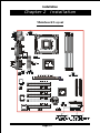
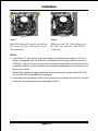
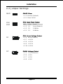
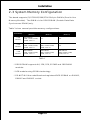
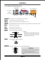
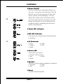
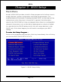
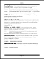
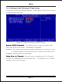
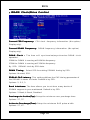
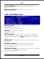
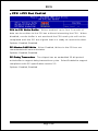
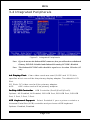
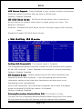
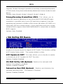
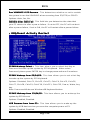
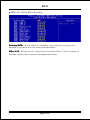
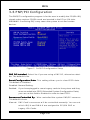
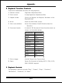
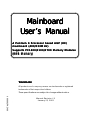
Mainboard User ’s Manual A Pentium 4 Processor based AGP (8X) mainboard (400/533MHz) Supports PC 1600/2100/2700 Memory Modules PC1600/2100/2700 (DDR Memory) TRADEMARK All products and company names are trademarks or registered trademarks of their respective holders. These specifications are subject to change without notice. $ 2), Manual Revision 1.0 January 23, 2003 Package Contents Contents A. (1) Mainboard B. (1) Users manual C. (1) Floppy ribbon cable D. (1) ATA-66/100 Hard drive ribbon cable E. (1) Driver and utility Deluxe item A. (1) USB2.0 Cable Optional item A. (1) SPD650 Card Table of Contents Page P ackage Contents Chapter 1 Features Mainboard Features .................................... 1-1 Chapter 2 Installation Mainboard Detailed Layout .......................... 2-1 CPU Installation ........................................... 2-2 Jumper Settings .......................................... 2-4 System Memory Configuration ..................... 2-5 Device Connectors ....................................... 2-6 STR (Suspend To RAM) Function ................. 2-8 Chapter 3 Award BIOS Setup BIOS Instructions ......................................... 3-1 Standard CMOS Setup ................................. 3-2 Advanced BIOS Features ............................. 3-3 Advanced Chipset Features .......................... 3-7 Integrated Peripherals .................................. 3-11 Power Management Setup .......................... 3-16 PNP/PCI Configuration Setup ....................... 3-21 PC Health Status ......................................... 3-23 Frequency/Voltage Control ............................ 3-24 Defaults Menu ............................................. 3-25 Supervisor/User Password Setting ............... 3-26 Exit Selecting ............................................... 3-27 Chapter 4 Driver Installation Easy Driver Installation ................................ 4-1 ALC650 Configuration Setup (6 Channel) ...... 4-2 Appendix Appendix A Avance Media Player User’s Guide .............. A-1 Features Chapter 1 Features Features: ! PROCESSOR ® ® - Socket 478 Intel Pentium 4 processor - Supports Hyper-Threading Technology Enabling the functionality of Hyper-Threading Technology for your computer system requires ALL of the following platform Components: CPU: " CPU " Chipset Chipset: " BIOS BIOS: " OS OS: ! ® ® An Intel Pentium 4 Processor with HT Technology. Chipset that supports HT Technology. A BIOS that supports HT Technology and has it enabled. An operating system that supports HT Technology. FRONT SIDE BUS - 400/533MHz ! CHIPSET - VIA P4X400 + VT8235 ! DRAM MODULE - 184pin DDR DIMM x 3 for PC1600/2100/2700 Memory - DRAM Size: 64MB to 3GB ! EXP ANSION SL OT EXPANSION SLOT - PCI x 5 - 8X AGP x 1 (1.5V only) ! ONBOARD I/O Winbond 83697HF LPC I/O integrated with - FDD, Parallel and Serial, Fast IR, Game Port Page 1-1 .A=JKHAI ! ONBOARD PCI / IDE - PCI Bus IDE Port with PIO / Ultra DMA-66/100/133 x 2 (Up to 4 Devices) ! I/O CONNECTOR - PS/2 Mouse and PS/2 style Keyboard - COM1, COM2 , Printer, Audio-in/out, MIC & Game Port connectors ! USB - USB supports USB2.0 specification - USB connector x 6 (4 for Optional) ! BIOS - Award Plug & Play BIOS ! Onboard LAN (Optional) - Integrate 10/100Mb fast Ethernet controller in chipset with external VIA VT6103 physical Layer by RJ-45 connector ! Built-in AC97 Digit al Audio (By Realtek ALC650) Digital - Compliant with AC97 2.2 Specification - 6 channel slot selectable DAC output for multi-channel applications - Supports digital SPDIF ! EXTENDED FUNCTION - Supports Hardware Monitoring Function by W83697HF - Supports STR (Suspend To RAM) power saving Function - Supports Wake-On-LAN Function ! FORM FFA A CTOR - 305mm x 225mm ATX Size Page 1-2 Installation Chapter 2 Installation Mainboard Layout Page 2-1 Installation 2-1 CPU Insertion CPU Insertion: Figure 2 Figure 1 Step 1 Step 2 Open the socket by raising the actuation lever. Insert the processor. Pin 1 Ensure proper pin 1 orientation by aligning the FC-PGA2 corner marking with the socket corner closest to the actuation arm tip. The pin field is keyed to prevent mis-oriented insertion. Dont force processor into socket. If it does not go in easily, check for mis-orientation and debris. Make sure the processor is fully inserted into the socket on all sides. Figure 3 Figure 4 Step 3 Step 4 Close the socket by lowering and locking the actuation lever. Install the Fan Heatsink. * Please do apply thermal compound between CPU and Heatsink. Page 2-2 Installation Figure 6 Figure 5 Step 5 Step 6 Install the Shroud Assembly and follow the arrow of Figure 5 for press the two Clip Assembly. Make sure the CPU fan is plugged to the CPU fan connector. The install complete. NOTE: 1. Intel PentiumTM 4 processor might be crashed if installed with a regular CPU Fan since it is equipped with all new micro- architecture that brings quite small size of CPU(Die). We recommend using Intels reference design thermal solution which is an active heatsink; an extruded aluminum heatsink based and a fan attached to the top on the fin array. Additionally, please do apply heatsink thermal compound or paste and install CPU fan to avoid CPU overheated and damaged. 2. According to the guidance of Intel Corp, please do not install the same CPU over 50 times as it will bend the pins and damage the CPU. Page 2-3 Installation 2-2 Jumper Settings JBAT1 CMOS Clear 1 = 1-2 Normal (Default) = 2-3 Clear CMOS JCK1 JCK2 JV1 1 CPU Host Clock Select 1 $ # JCK1 JCK2 Clock = 1-2 1-2 Auto (Default) = 1-2 2-3 133MHz = 2-3 2-3 166MHz CPU Vcore V oltage Select Voltage = 1-6 None (Default) = 2-7 +0.05V = 3-8 +0.10V = 4-9 +0.15V = 5-10 +0.20V JV2 # & " DIMM V oltage Select Voltage = 1-5 +0.1V (Default) = 2-6 +0.2V = 3-7 +0.3V = 4-8 +0.4V Page 2-4 Installation 2-3 System Memory Configuration The board supports (3) PC1600/2100/2700 184-pin DIMMs (Dual In-line Memory Module). The DIMMs is for DDR SDRAM (Double-Data-Rate Synchronous DRAM) only. Table 1 show several possible memory configurations. DDR DIMM 1 (Bank 0/1) Total Me mory DDR DIMM 2 (Bank 2/3) DDR DIMM 3 (Bank 4/5) = 1GB Maximum DDR SDRAM* 64MB, 128MB, 256MB, 512MB, 1GB* X 1 None None = 2GB Maximum DDR SDRAM* 64MB, 128MB, 256MB, 512MB, 1GB* X 1 DDR SDRAM* 64MB, 128MB, 256MB, 512MB, 1GB* X 1 None = 3GB Maximum DDR SDRAM* 64MB, 128MB, 256MB, 512MB, 1GB* X 1 DDR SDRAM* 64MB, 128MB, 256MB, 512MB, 1GB* X 1 DDR SDRAM* 64MB, 128MB, 256MB, 512MB, 1GB* X 1 Table 1 * DDR SDRAM supports 64, 128, 256, 512MB and 1GB DIMM modules. * 1GB module using 512Mb technology. * DO NOT MIX the unbuffered and registered DDR SDRAM on DIMM1 , DIMM2 and DIMM3 socket. Page 2-5 Installation 2-4 Device Connectors RJ-45 LAN (Optional) Joystick/Midi port parallel port PS/2 Mouse PS/2 KEYBOARD USB2.0 ports COM1 Line_out Line_in Mic_in COM2 FAN1/2 FAN1/2:: The plug-in for CPU/Chassis Fan power WOL1 WOL1:: WOL (Wake On LAN) Connector FDD1 FDD1:: Floppy Controller Connector (Black color) IDE1/2 IDE1/2:: Ultra DMA66/100/133 Primary/Secondary IDE Connector (Blue color) PW1 PW1:: ATX Power Connector CD1 CD1: CD Audio_IN Connector AUX1 AUX1: Auxiliary Line_IN Connector AUD2 AUD2: Front Panel Audio Connector Settings: Pins (5-6) & (9-10) Short (default): Only the Onboard Rear Audio Speaker can be used. Pins (5-6) & (9-10) Open: Only Front Panel Audio Speaker can be used. SPDIF SPDIF: Sony/Philips Digital Interface SPDIF_OUT GND NC $ # VCC SPDIF_IN USB2/3 USB2/3:: USB port header pins for four USB2.0 ports. VCC $ CAUTION ! GND -Data +Data +Data -Data GND VCC # Please make sure the USB cable has the same pin assignment. The different pin assignment may be caused damage of system. If you need the USB cable, please contact our retailer. Page 2-6 Installation ! Power On/Off (This is connected to the power button on the case. Using the Soft-Off by Pwr-BTTN feature, you can choose either Instant Off (turns system off immediately), or 4 sec J2 delay (you need to push the button down for 4 seconds before the system turns off). When the system is in 4 sec delay mode, suspend mode is enabled by pushing the button momentarily.) ! Turbo ! IDE LED indicator LED indicator LED ON when Onboard PCI IDE Hard disks is activate J1 ! IR Connector 1. VCC 4. GND 2. CIRRX 5. IRTX 3. IRRX ! Power LED Power LED connector 1. Power LED(+) 4. NC 2. N/C 5. GND 3. GND ! Speaker Connect to the system's speaker for beeping 1. Speaker 3. GND 2. N/C 4. VCC ! Reset Closed to restart system. Page 2-7 Installation 2-5 STR (Suspend To RAM) Function This mainboard supports the STR (Suspend To RAM) power management scheme by maintaining the appropriate power states in the DDR SDRAM interface signals. The power source to the DDR SDRAM must be kept active during STR (ACPI S3). Advanced Configuration Power Interface (ACPI) provides many Energy Saving Features for operating systems that support Instant ON and QuickStartTM function. 1. Use the STR functionality to save system power, you are recommended to confirm the following requirements: a. Install ACPI qualified add-on cards (such as AGP, LAN, and modem cards). b. In BIOS under Power Management Setup (refer to Chapter 3), select “ACPI Suspend Type: S3(STR)” and “USB Resume from S3: Enabled” (if you have a USB mouse or keyboard device). c. Install Windows® XP/2000/ME/98SE. d. Restart the system. e. Open the Control Panel Power Management application, and click the Advanced tab. In the Power buttons section, select “Stand By” from the drop-down lists. 2. To enable the STR function, click the START button and choose Shut Down. In the Shut Down Windows dialog box, select the Stand By option to enter STR mode. The following lists the differences between STR power saving mode and Green (or Suspend) mode: a. STR is the most advanced Power Management mode. b. STR cuts all the power supplied to peripherals except to memory max. power saving. c. STR saves and keeps all on-screen data including any executed applications to DDR SDRAM. d. In STR mode, you must push the power button (connected to the onboard J2 pin), click your USB mouse buttons, or press your USB keyboard keys to wake up your system to the last display. Page 2-8 BIOS Chapter 3 BIOS Setup Main Menu Award’s ROM BIOS provides a built-in Setup program which allows user to modify the basic system configuration and hardware parameters. The modified data will be stored in a battery-backed CMOS, so that data will be retained even when the power is turned off. In general, the information saved in the CMOS RAM will stay unchanged unless there is a configuration change in the system, such as hard drive replacement or a device is added. It is possible for the CMOS battery to fail, this will cause data loss in the CMOS only. If this does happen you will need to reconfigure your BIOS settings. To enter the Setup P rogram : Program Power on the computer and press the <Del> key immediately, this will bring you into the BIOS CMOS SETUP UTILITY. Figure 1: CMOS Setup Utility Page 3-1 BIOS The menu displays all the major selection items. Select the item you need to reconfigure. The selection is made by moving the cursor (press any direction key ) to the item and pressing the ‘Enter’ key. An on-line help message is displayed at the bottom of the screen as the cursor is moved to various items which provides a better understanding of each function. When a selection is made, the menu of the selected item will appear so that the user can modify associated configuration parameters. 3-1 Standard CMOS Setup Choose “Standard CMOS Setup” in the CMOS SETUP UTILITY Menu (Figure 2). The Standard CMOS Setup allows the user to configure system settings such as the current date and time, type of hard disk drive installed, floppy drive type, and display type. Memory size is auto-detected by the BIOS and displayed for your reference. When a field is highlighted (use direction keys to move the cursor and the <Enter> key to select), the entries in the field can be changed by pressing the <PgDn> or the <PgUp> key. Figure 2: Standard CMOS Setup Page 3-2 BIOS NOTE: If the hard disk Primary Master/Slave and Secondary Master/ Slave are set to Auto, then the hard disk size and model will be auto-detected. NOTE: The “Halt On:” field is used to determine when to halt the system by the BIOS if an error occurs. NOTE: Floppy 3 Mode support is a mode used to support a special 3. 5” drive used in Japan. This is a 3.5” disk that stores only 1.2 MB, the default setting for this is disabled. 3-2 Advanced BIOS Features Selecting the “Advanced BIOS Features” option in the CMOS SETUP UTILITY menu allows users to change system related parameters in the displayed menu. This menu shows all of the manufacturer’s default values for the board. Pressing the [F1] key will display a help message for the selected item. Figure 3: BIOS Features Setup Page 3-3 BIOS Virus W arning Warning arning: During and after the system boots up, any attempt to write to the boot sector or partition table of the hard disk drive will halt the system and an error message will appear. You should then run an anti-virus program to locate the virus. Keep in mind that this feature protects only the boot sector, not the entire hard drive. The default value is Disabled. Enabled: Activates automatically when the system boots up causing a warning message to appear when anything attempts to access the boot sector. Disabled: No warning message will appear when anything attempts to access the boot sector. Note: Many disk diagnostic programs that access the boot sector table can trigger the virus warning message. If you plan to run such a program, we recommend that you first disable the virus warning. CPU L1 L1& L2 Cache Cache: These two categories speed up memory access. However, it depends on CPU chipset design. Options: Enabled, Disabled. HyperThreading T echnology Hyper-Threading Technology echnology:: Enables the CPU Hyper-Threading Technology. Options: Enables, Disabled. Note: R e c o m m e n d s e n a b l i n g H y p e r --T Threading T echnology Te on system with Windows XP and Linux 2.4 and disabling for legacy OS. CPU L2 Cache ECC Checking Checking: These control if the CPU’s L2 Cache will support Error Checking and Correcting(ECC). The default is Disabled. Enabled: Enabled ECC support for the CPU’s L2 cache. Performance will decrease 2% ~ 4%. Disabled: Disables ECC support for the CPU’s L2 cache. Quick P ower On Self T est Power Test est: This category speeds up the Power On Self Test (POST). The default is Enabled. Enabled: This setting will shorten or skip of the items checked during POST. Disabled: Normal POST. Page 3-4 BIOS First /Second/Third/Other Boot Device Device: The BIOS attempts to load the operating system from the devices in the sequence selected in these items. Options: Floppy, LS120, HDD-0, SCSI, CDROM, HDD-1, HDD-2, HDD-3, ZIP100, LAN, Disabled. Swap Floppy Drive Drive: This will swap your physical drive letters A & B if you are using two floppy disks. The default is Disabled. Options: Enabled, Disabled. Boot Up Floppy Seek Seek: During Power-On-Self-Test (POST), BIOS will determine if the floppy disk drive installed is 40 or 80 tracks. Only 360K type is 40 tracks while 760K, 1.2MB and 1.44MB are all 80 tracks. The default is Enabled. Enabled: The BIOS will search the floppy disk drive to determine if it is 40 or 80 tracks. Disabled: The BIOS will not search for the type of floppy disk drive by track number. Note: BIOS can not tell the difference between 720K, 1.2MB and 1. 44MB drive types as they are all 80 tracks. Boot Up NumLock Status Status: This controls the state of the NumLock key when the system boots. The default is On. On: The keypad acts as a 10-key pad. Off: The keypad acts like the cursor keys. ate Setting Rate Setting: This determines the keystrokes repeat rate. Typematic R The default is Disabled. Enabled: Allows typematic rate and typematic delay programming. Disabled: The typematic rate and typematic delay will be controlled by the keyboard controller in your system. Typematic R ate (Chars/Sec) Rate (Chars/Sec): This is the number of characters that will be repeated by a keyboard press. The default is 6. Options: 6, 8, 10, 12, 15, 20, 24, 30 characters per second. Typematic Delay (msec) (msec): This setting controls the time between the first and the second character displayed by typematic auto-repeat. The default is 250. Options: 250, 500, 750, 1000 msec. Page 3-5 BIOS Security Option Option: This category allows you to limit access to the System and Setup, or just to Setup. The default is Setup. System: The system will not boot and the access to Setup will be denied if the correct password is not entered at the prompt. Setup: The system will boot; but the access to Setup will be denied if the incorrect password is not entered at the prompt. APIC Mode Mode: This item allows you to enable APIC (Advanced Programmable Interrupt Controller) functionality. Options: Enabled, Disabled. MPS V ersion Control For OS Version OS: Specifies the Multiprocessor Specification (MPS). Version 1.4 supports multiple PCI bus configurations by incorporating extended bus definitions. Enable this for Windows NT or Linux. For older operating systems, select Version 1.1. Options: 1.1, 1.4. OS Select For DRAM > 64MB 64MB: Some operating systems require special handling. Use this option only if your system has greater than 64MB of memory. The default is Non-OS2. OS2: Select this if you are running the OS/2 operating system with greater than 64MB of RAM. Non-OS2: Select this for all other operating systems and configurations. Video BIOS Shadow Shadow: This option allows video BIOS to be copied into RAM. Video Shadowing will increase the video performance of your system. The default is Enabled. Enabled: Video shadow is enabled. Disabled: Video shadow is disabled. Small Logo (EP A) Show (EPA) Show:: If the BIOS combined a bit map file internal, this option lets users determine it showing or not at screen top-Right corner. Options: Enabled, Disabled. Page 3-6 BIOS 3-3 Advanced Chipset Features Choose the “Advanced Chipset Features” in the CMOS SETUP UTILITY menu to display following menu. Figure 4: Advanced Chipset Features Setup System BIOS Cacheable Cacheable: This allows you to copy your BIOS code from slow ROM to fast RAM. The default is Disabled. Enabled: The option will improve system performance. However, if any program writes to this memory area, a system error may result. Disabled: System BIOS non-cacheable. Delay Prior to Thermal Thermal: Set this item to enable the CPU Thermal function to engage after the specified time. Options: 4, 8, 16, 32 minutes. Page 3-7 The default is 16 minutes. BIOS DRAM Clock/Drive Control 133MHz 133MHz Current FSB Frequency Frequency:: CPU clock frequency information. (No option/ Display only). Current DRAM Frequency Frequency:: DRAM frequency information. (No option/ Display only). DRAM Clock : The item will synchronize/asynchronize DRAM clock operation. 100MHz: DRAM is running at 100MHz frequency. 133MHz: DRAM is running at 133MHz frequency. By SPD: SDRAM clock by SPD data. DRAM Timing : Select SPD for setting SDRAM timing by SPD. Options: Manual, SPD. SDRAM CAS Latency Latency: This setting defines the CAS timing parameter of the SDRAM in terms of clocks. Default is by SPD. Options: 2, 2.5, 3. Bank Interleave Interleave:: The item allows you to set how many banks of SDRAM support in your mainboard. Default is by SPD. Options: 2 Bank, 4 Bank, Disabled. Precharge to Active(T rp) Active(Trp) rp):: Setup the minimum row precharge time. Options: 2T, 3T. Active to P recharge(T ras) Precharge(T recharge(Tras) ras):: Setup the minimum RAS pulse width. Options: 5T, 6T. Page 3-8 BIOS Active to CMD(T rcd) CMD(Trcd) rcd):: Setup the minimum CAS to RAS delay. Options: 2T, 3T. DRAM Command Rate Rate: Setup the timing at each cycle. Options: Auto, Manual. AGP & P2P Bridge Control AGP Aperture Size Size: The amount of system memory that the AGP card is allowed to share with. Options: 4, 8, 16, 32, 64, 128, 256MB. AGP Mode Mode: Chipset AGP Mode support. The option: 1X, 2X, 4X. AGP Driving Control Control: This item allows you to adjust the AGP driving force. Choose Manual to key in a AGP Driving Value in the next selection. This field is recommended to set in Auto for avoiding any error in your system. AGP Fast Write Write: Selecting Enabled allows to use Fast Write Protocol for 4X AGP card. AGP Master 1 WS Write Write: When Enabled, Writes to the AGP (Accelerated Graphics Port) are executed with one wait states. Options: Enabled, Disabled. AGP Master 1 WS Read Read: When Enabled, Reads to the AGP (Accelerated Graphics Port) are executed with one wait states. Options: Enabled, Disabled. Page 3-9 BIOS CPU & PCI Bus Control CPU to PCI Write Buffer Buffer: When enabled, up to four D words of data can be written to the PCI bus without interruting the CPU. When disabled, a write buffer is not used and the CPU read cycle will not be completed until the PCI bus signals that it is ready to receive the data. Options: Enabled, Disabled. PCI Master 0 WS Write Write: When Enabled, Writes to the PCI bus are commanded with zero wait states. Options: Enabled, Disabled. PCI Delay T ransaction Transaction ransaction: The chipset has an embedded 32-bit posted write buffer to support delay transactions cycles. Select Enabled to support compliance with PCI specification version 2.2. Options: Enabled, Disabled. Page 3-10 BIOS 3-4 Integrated Peripherals Figure 5: Integrated Peripherals Note: If you do not use the Onboard IDE connector, then you will need to set Onboard Primary PCI IDE: Disabled and Onboard Secondary PCI IDE: Disabled Note: The Onboard PCI IDE cable should be equal to or less than 18 inches (45 cm.). Init Display First First:: If two video cards are used (1 AGP and 1 PCI) this specifies which one will be the primary display adapter. The default is PCI Slot. PCI Slots: PCI video card will be primary adapter. AGP: AGP video card will be primary adapter. OnChip USB Controller Controller: USB Controller (Port1)(Port2)(Port3). Options: All Disabled, All Enabled, 1&2 USB Port, 2&3 USB Port, 1&3 USB Port, 1 Port, 2 Port, 3 Port. USB Keyboard Support Support: Select Enabled if your system contains a Universal Serial Bus (USB) controller and you have a USB keyboard. Options: Enabled, Disabled. Page 3-11 BIOS USB Mouse Support Support: Select Enabled if your system contains a Universal Serial Bus (USB) controller and you have a USB Mouse. Options: Enabled, Disabled. IDE HDD Block Mode Mode: IDE Block Mode allows the controller to access blocks of sectors rather than a single sector at a time. The default is Enabled. Enabled: Enabled IDE HDD Block Mode. Provides higher HDD transfer rates. Disabled: Disable IDE HDD Block Mode. VIA OnChip IDE Device OnChip IDE Channel0/1 Channel0/1: The default value is Enabled. The integrated peripheral controller contains an IDE interface with support for two IDE channels. Select Enabled to activate each channel separately. Options: Enabled, Disabled. IDE Prefetch Mode Mode: Enable prefetching for IDE drive interfaces that support its faster drive accesses. If you are getting disk drive errors, change the setting to omit the drive interface where the errors occur. Depending on the configuration of your IDE subsystem, this field may not appear, and it does not appear when the Internal PCI/IDE field, above, is Disabled. Options: Enabled, Disabled. Primary/Secondary Master/Slave PIO PIO:: The default is Auto. The four IDE PIO (Programmed Input/Output) fields let you set a PIO mode (0-4) for each of the four IDE devices that the onboard IDE interface Page 3-12 BIOS supports. Modes 0 through 4 provide successively increased performance. In Auto mode, the system automatically determines the best mode for each device. Options: Auto, Mode 0, Mode 1, Mode 2, Mode 3, Mode 4. Primary/Secondary Master/Slave UDMA UDMA: This allows you to select the mode of operation for the Ultra DMA33 /66/100/133implementation is possible only if your IDE hard drive supports it and the operating environment includes a DMA driver (Windows 95 OSR2 or a third-party IDE bus master driver). If your hard drive and your system software both support Ultra DMA33/66/100/133, select Auto to enable BIOS support. Options: Auto, Disabled. VIA OnChip PCI Device VIA-3058 AC97 Audio Audio: This item allows you to decide to Auto/ disable the chipset family to support AC97 Audio. The function setting AC97 Audio Codec states. The system default is Auto. AC97 Speaker At POST POST: This item allows you to decide to enable or disable the AC97 Speaker At POST Function. Options: Enabled, Disabled. VIA-3043 OnChip LAN (Optional) (Optional): Enables the onboard LAN feature. The default is Enabled. Options: Enabled, Disabled. Onboard Lan Boot ROM (Optional) : Enables and disables the onboard LAN Boot ROM. The default is Disabled. Options: Enabled, Disabled. Page 3-13 BIOS Super IO Device Onboard FDC Controller Controller: Select Enabled if your system has a floppy disk controller (FDC) installed on the system board and you wish to use it. If you install and-in FDC or the system has no floppy drive, select Disabled in this field. Options: Enabled, Disabled. Onboard Serial Port 1/2 1/2: Select an address and corresponding interrupt for the first and second serial ports. Options: 3F8/IRQ4, 2E8/IRQ3, 3E8/IRQ4, 2F8/IRQ3, Disabled, Auto. UART Mode Select Select: This filed allows the users to configure what IR mode the 2nd serial port should use. The default is Normal. Options: Normal, IrDA and ASKIR. RxD, TxD Active : This field configures the receive and transmit signals generated from the IR port. The default is Hi Lo (when UART Mode Select is not set to Normal). Options: Hi Hi, Hi Lo, Lo Hi, and Lo Lo. IR T ransmission delay Transmission delay: This item allows you to enabled/disable IR transmission delay. Options: Enabled, Disabled. UR2 Duplex Mode Mode: This item allows you to select IR half/full duplex function. Options: Half, Full. Page 3-14 BIOS Use IR Pins Pins: This item allows you to select IR transmission routes, one is RxD2, TxD2 (COM Port) and the other is IR-Rx2Tx2. Options: IR-Rx2Tx2, RxD2, TxD2. Onboard Parallel port port: This field allows the user to configure the LPT port. Options: 378/IRQ7, 278/IRQ5, 3BC/IRQ7, Disabled. Parallel Port Mode Mode: This field allows the user to select the parallel port mode. Options: SPP, EPP, ECP, ECP+EPP. EPP Mode Select Select: This item allows you to determine the IR transfer mode of onboard I/O chip. Options: EPP1.9, EPP1.7. ECP Mode USE DMA DMA: This field allows the user to select DMA1 or DMA3 for the ECP mode. Options: DMA1, DMA3. Game Port Address Address: Select an address for the Game port. Options: 201, 209, Disabled. Midi Port Address Address: Select an address for the Midi port. Options: 290, 300, 330, Disabled. Midi Port IRQ IRQ: Select an interrupt for the Midi port. Options: 5, 10. Page 3-15 BIOS 3-5 Power Management Setup Choose the “Power Management Setup” in the CMOS SETUP UTILITY to display the following screen. This menu allows the user to modify the power management parameters and IRQ signals. In general, these parameters should not be changed unless it’s absolutely necessary. Figure 6: Power Management Setup ACPI Function Function: This option allows you to select ACPI Function. Options: Enabled, Disabled. ACPI Suspend T ype Type ype: This item allows you to select S1(POS) or S3(STR) function. Options: S1(POS), S3(STR). Power Management Option Option: Use this to select your Power Management selection. The default is User define. Max. saving: Maximum power savings. Inactivity period is 1 minute in each mode. Min. saving: Minimum power savings. Inactivity period is 1 hour in each mode. User define: Allows user to define PM Timers parameters to control power saving mode. Page 3-16 BIOS HDD Power Down Down:: When enabled and after the set time of system inactivity, the hard disk drive will be powered down while all other devices remain active. Options: Enabled, Disabled. Suspend Mode Mode:: When enabled and after the set time of system inactivity, all devices except the CPU will be shut off. Options: Enabled, Disabled. Video Off Option Option: Tells you what time frame that the video will be disabled under current power management settings. Always On: Suspend->Off: Video power off not controlled by power management. Video powers off after time shown in suspend mode setting. Video Off Method Method: This option allows you to select how the video will be disabled by the power management. The default is V/H Sync + Blank V/H Sync + Blank: System turns off vertical and horizontal synchronization ports and writes blanks to the video buffer. DPMS Support: Select this option if your monitor supports the Display Power Management Signaling (DPMS) standard of the Video Electronics Standards Association (VESA). Use the software supplied for your video subsystem to select video power management values. Blank Screen: System only writes blanks to the video buffer. MODEM Use IRQ IRQ: Name the interrupt request (IRQ) line assigned to the modem (if any) on your system. Activity of the selected IRQ always awakens the system. Default is IRQ 3. Options: N/A, 3, 4, 5, 7, 9, 10, 11 Soft-Off by PWRBTN PWRBTN: Use this to select your soft-off function. The default is Instant Off. Instant Off: Turns off the system instantly. Delay 4 Second : Turns off the system after a 4 second delay. If momentary press of button, the system will go into Suspend Mode. Press the power botton again to make system back to work. Page 3-17 BIOS Run VGABIOS if S3 Resume Resume: This determines whether or not to enable the system to run the VGA BIOS when resuming from S3(STR) or S1&S3. Options: Auto, Yes, No. PWRON After PWR-Fail PWR-Fail: This field lets you determine the state that your PC returns to after a power failure. If set to OFF, the PC will not boot after a power failure, if set to ON, the PC will restart after a power failure. IRQ/Event Activity Dectect PS2KB W akeup Select : This item allows you to select Hot Key or Wakeup Password to wake-up the system by PS2 Keyboard. When select Password, please press ENTER key to change password max 8 numbers. PS2KB W Wakeup S3/S4/S5:: This item allows you to set a Hot Key akeup from S3/S4/S5 to wake-up the system by PS2 Keyboard. Options: Disabled, Ctrl+F1, Ctrl+F2, Ctrl+F3, Ctrl+F4, Ctrl+F5, Ctrl+F6, Ctrl+F7, Ctrl+F8, Ctrl+F9, Ctrl+F10, Ctrl+F11, Ctrl+F12, Power, Wake, Any key. Note: Power and Wake are Windows98 Keyboard button. PS2MS W akeup from S3/S4/S5 Wakeup S3/S4/S5:: This item allows you to wake-up the system by PS2 Mouse. Options: Enabled, Disabled. USB Resume from from S3 : This item allows you to wake-up the system by USB device when you save the computer power at S3. Options: Enabled, Disabled. Page 3-18 BIOS VGA VGA:: When set to On, any event occurring at a VGA port will awaken a system which has been powered down. LPT & COM COM:: When set to LPT/COM, any event occurring at a COM (serial)/LPT (printer) port will awaken a system which has been powered down. HDD & FDD FDD: When set to On, any event occurring at a hard or floppy drive port will awaken a system which has been powered down. PCI Master Master: When set to Off, any event occurring to the DMA controller will awaken a system which has been powered down. PowerOn by PCI Card Card: An input signal from PME on the PCI card awakens the system from a soft off state. Power On by Onboard Lan Lan: When set to Enable rtc alarm resume, you could set the date (of month) and timer (hh:mm:ss), any event occurring at will awaken a system which has been powered down. Wake Up On LAN/Ring LAN/Ring: When set to Enabled, any event occurring to the Modem Ring and LAN will awaken a system which has been powered down. RTC Alarm Resume Resume: When set to Enable rtc alarm resume, you could set the date (of month) and timer (hh:mm:ss), any event occurring at will awaken a system which has been powered down. Page 3-19 BIOS IRQs Activity Monitoring Primary INTR INTR: When set to On (default), any event occurring at will awaken a system which has been powered down. IRQs 3-15 3-15: Allows you to set system to monitor IRQs 3-15 for activity to awaken system form a power managerment mode. Page 3-20 BIOS 3-6 PNP/PCI Configuration The PNP/PCI configuration program is for the user to modify the PCI/ISA IRQ signals when various PCI/ISA cards are inserted in the PCI or ISA slots. WARNING: Conflicting IRQ’s may cause the system to not find certain devices. Figure 7: PnP/PCI Configuration Setup PNP OS Installed Installed: Select Yes if you are using a PNP OS, otherwise select No. The default is No. Reset Configuration Data Data: This setting allows you to clear ESCD data. The default is Disabled Disabled: Normal Setting. Enabled: If you have plugged in some Legacy cards to the system and they were recorded into ESCD (Extended System Configuration Data), you can set this field to Enabled in order to clear ESCD. Resources Controlled By By: Who controlled the system PNP/PCI resource. The dafault is Auto. Manual: PNP Card’s resources will be controlled manually. You can set which IRQ-X and DMA-X are assigned to PCI/ISA PNP or Legacy ISA Cards. Page 3-21 BIOS Auto: If your ISA card and PCI card are all PNP cards, BIOS will assign the interrupt resource automatically. PCI/VGA Palette Snoop Snoop:: Leave this field at Disabled. Options: Enabled, Disabled. Assign IRQ For VGA VGA: This item allows BIOS to assign whether IRQ is with VGA or not. If you have not connect the VGA device. Can release the IRQ for other device. The default is Enabled. Options: Enabled, Disabled. Assign IRQ For USB USB: This item allows BIOS to assign whether IRQ is with USB or not. If you have not connect the USB device. Can release the IRQ for other device. The default is Enabled. Options: Enabled, Disabled. Page 3-22 BIOS 3-7 PC Health Status 31oC/87oF 0oC/32oF 6135 RPM 0 RPM 1.62V 1.52V 4.97V 12.16V 3.35V 2.57V 3.02V 4.89V CPU W arning T emperature Warning Temperature emperature:: This is the temperature that the computer will respond to an overheating CPU. The default is Disabled. Options: Disabled, 50OC/122OF, 53OC/127OF, 56OC/133OF, 60OC/140OF, 63OC/ 145OF, 66OC/151OF, 70OC/158OF. Current System T emperature Temperature emperature:: This is the Current temperature of the system. Current CPU T emperature Temperature emperature:: This is the Current temperature of the CPU. Current CPU/Chassis FAN Speed Speed: The current CPU/Chassis fan speed in RPMs. Vcore (V) (V): The voltage level of the CPU Vcore. Vagp (V) (V): The voltage level of Power supplied to AGP card. +5V T(V), 5VSB(V) +5V,, +12V +12V,, VBA VBAT(V), 5VSB(V): The voltage level of the switch power supply. 3.3V 3.3V: The voltage level of the CPU Vio. Vdimm Vdimm: The voltage level of the DRAM. Page 3-23 BIOS CPU Shutdown T emperature Temperature emperature:: This is the temperature that the computer will turn off the power to combat the effects of an overheating system. (requires ACPI to be enabled in Power Management BIOS and ACPI compliant operating system.) The default is Disabled. Options available are 60oC/140oF to 75oC/167oF in increments of 5oC. 3-8 Frequency/Voltage Control CPU Clock Ratio : This item allows you to select the CPU clock ratio. Auto Detect PCI/DIMM Clk Clk:When enabled the motherboard will automatically disable the clock source for a DIMM socket which does not have a module in it. Same applies for PCI slots. The default is Enabled. Spread Spectrum Spectrum: This item allows you to enable/disable the spread spectrum modulate. CPU Clock Clock:: The mainboard is designed to set the CPU clock via BIOS. This item allows you to to adjust CPU clock 1MHz by step. The default speed depends on what CPU was installed. Note:Overclocking failure will cause system No display problem. At this moment, please press “ Insert ” key to back to the initial or default setting to boot up your system. Page 3-24 BIOS 3-9 Defaults Menu Selecting “Defaults” from the main menu shows you two options which are described below Load Fail-Safe Defaults When you press <Enter> on this item you get a confirmation dialog box with a message similar to: Load Fail-Safe Defaults (Y/N) ? N Pressing ‘Y’ loads the BIOS default values for the most stable, minimalperformance system operations. Load Optimized Defaults When you press <Enter> on this item you get a confirmation dialog box with a message similar to: Load Optimized Defaults (Y/N) ? N Pressing ‘Y’ loads the default values that are factory settings for optimal performance system operations. Page 3-25 BIOS 3-10 Supervisor/User Password Setting You can set either supervisor or user password, or both of then. The differences between are: supervisor password : can enter and change Options of the setup menus. user password change : just can only enter but do not have the right to Options of the setup menus. When you select this function, the following message will appear at the center of the screen to assist you in creating a password. ENTER PASSWORD: Type the password, up to eight characters in length, and press <Enter>. The password typed now will clear any previously entered password from CMOS memory. You will be asked to confirm the password. Type the password again and press <Enter>. You may also press <Esc> to abort the selection and not enter a password. To disable a password, just press <Enter> when you are prompted to enter the password. A message will confirm the password will be disabled. Once the password is disabled, the system will boot and you can enter Setup freely. PASSWORD DISABLED. When a password has been enabled, you will be prompted to enter it every time you try to enter Setup. This prevents an unauthorized person from changing any part of your system configuration. Additionally, when a password is enabled, you can also require the BIOS to request a password every time your system is rebooted. This would prevent unauthorized use of your computer. You determine when the password is required within the BIOS Features Setup Menu and its Security option. If the Security option is set to “System”, the password will be required both at boot and at entry to Setup. If set to “Setup”, prompting only occurs when trying to enter Setup. Page 3-26 BIOS 3-11 Exit Selecting Save & Exit Setup Pressing <Enter> on this item asks for confirmation: Save to CMOS and EXIT (Y/N)? ; Pressing “Y” stores the selections made in the menus in CMOS – a special section of memory that stays on after you turn your system off. The next time you boot your computer, the BIOS configures your system according to the Setup selections stored in CMOS. After saving the values the system is restarted again. Exit Without Saving Pressing <Enter> on this item asks for confirmation: Quit without saving (Y/N)? ; This allows you to exit Setup without storing in CMOS any change. The previous selections remain in effect. This exits the Setup utility and restarts your computer. Page 3-27 BIOS Page Left Blank Page 3-28 Driver Installation Chapter 4 Driver Installation Easy Driver Installation 81)2":"5-41-5 VIA SERVICE PACK 4IN1 DRIVER ALC201A/650 AC97 AUDIO DRIVER VIA 6103 LAN DRIVER (Optional) VIA 8235 USB 2.0 DRIVER (README) ACROBAT READER CD EXPLORER EXIT Insert the bundled autorun driver CD CD-- disk. S t e p 1 : Click “SERVICE P A CK 4IN1 DRIVER” PA DRIVER”.. Install all components recommended. S t e p 2 : Click “ALC201A/650 A C97 DRIVER” to install audio AC97 driver. S t e p 3 : Click “ VIA 6103 LAN DRIVER” to install LAN driver. (Optional) S t e p 4 : Click “ VIA 8235 USB2.0 DRIVER” to install USB2.0 driver. (Please refer to README.TXT file). Page 4-1 Driver Installation ALC650 Configuration Setup (6 Channel) ! To enable ALC650 Function <Figure 1> 1. Right-click Sound Effect button in the tool bar display currently selected Titles. Select Sound Manager Manager. Sound Effect: <Figure 2> 2. Click Sound Effect button and select Environment from the drop-down menu. Page 4-2 Driver Installation Equalizer: <Figure 3> 3. Click Equalizer and setup the value of dB. Speak Configutation: <Figure 4> 4. Click Line in and Mic in buttons to enable 6 channel function as this is required for the ALC650. Page 4-3 Driver Installation Speak Configutation: <Figure 5> 5. The selected screen appears. Speaker T est: Test: <Figure 6> er T est button and click on the speakers directly which 6. Click Speak Speaker Test show on the screen to test it. Page 4-4 Driver Installation General: <Figure 7> 7. General Information for user reference. Page 4-5 Driver Installation Page Left Blank Page 4-6 Appendix Appendix A A-1 Avance® Media Player User’s Guide Avance ® Media Player Platform H " A # D $ 06 - Reo Speedwagon I ! H C J & " % # $ ! 06-Reo Speedwagon - K 03:31 K B E G F Functional Descriptions A . Playback Windows Display Playback windows displays the following mode information: 1. Playback Time Display 2. Voice Cancellation Mode Display 3. Pitch Mode Display 4. Surround Sound Mode Display A-1 Appendix B . Playback Function Controls There are 8 selectable functions for the playback: 1. Volume control High/Low Adjustment Bar. 2. Pitch control 4-step High/Low Adjustment Bar. 3. Repeat mode Choice of Repeat, All Repeat, Random or No Repeat Mode. 4. Mute Mute On/Off Mode select. 5. Voice cancellation Voice Cancellation On/Off Mode select for Karaoke. 6. Surround mode A total of 26 Surround Sound mode select as shown in the table below. Surround mode Surround mode Generic Stone corridor Padded Alley Room Forrest Bathroom City Living room Mountain Stone Quarry Auditorium Plain Concert Parking lot Cave Sewer pipe Arena Under water Hangar Drug Carpet Dizzy Hallway Psychological 7. Skin change Media Player Skin Type select. 8. Open Open file formats including MP3, CDA, MDI, WAV & WMA support. C . Playback Controls The playback controls include “Play”, “Pause”, “Stop”, “Previous”, “Backward”, “Forward”, & “Next”. A-2 Appendix D . Seeking bar Display Animated Playback Status E . Title/Play List Windows Display Currently Selected Title(s) F . Title/Play List Edit Controls There title/play list controls include “Add”, “Del”, “Clear”, “Load”, & “Store”. 1. Add Add to the Title/Play List. 2. Del Remove form the Title/Play List. 3. Clear Clear the Title/Play Lost. 4. Load Load Title/Play List. 5. Store Save Title/Play List. G . Title/Play List Scroll bar Scroll Up/Down the Title/Play List. H . Recording Function Controls The recording function controls include “Input”, “Save:, “New”, “Rec”, “Stop”, & “Play”. 1. Input Input soruce select. 2. Save Save to file. 3. New Open new file & select format includes Sampling Rate, Sampling bit, Mono or Stereo. 4. Rec Start Rec. 5. Stop Stop Rec. 6. Play Playback Rec file. I . REC/Playback Time Display Displays REC/Playback Time. A-3 Appendix J . Platform Display Panel Controls The platform display panel control include “Minimize” “Close”. 1. Minimize Minimize Platform Display Panel. 2. Close Close/Exit Platform Display Panel. K. Equalizer Control Panel The Equalizer Control Panel include “On/Off” & “Preset”. 1. On/Off Enable/Disable Equalizer. 2. Preset Clear Equalizer setting to default value. A-4