1
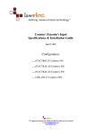
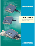
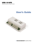
_EN_
VIBdaq 16.1
USER MANUAL
VIBDAQ 16.1
USER MANUAL _EN_
Table of content
1. Introduction ............................................................................................................................ 4
2. VIBdaq 16.1 module technical data ....................................................................................... 5
3. VIBdaq 16.1 module description ............................................................................................ 6
4. Installation .............................................................................................................................. 7
4.1
Drivers and software installation ................................................................................ 7
4.2
Plug VIBdaq 16.1 card to computer ............................................................................ 8
5. Run VIBdaq 16.1 card in DASYLab® ...................................................................................... 12
5.1
Install the drivers in the DASYLab®............................................................................ 12
5.2
Starting VIBdaq 16.1 card in DASYLab® .................................................................... 13
List of images
Figure 3.1 » VIBdaq 16.1 module description ............................................................................ 6
Figure 4.1 » The main window of installer ................................................................................. 7
Figure 4.2 » Documentation selection window ......................................................................... 8
Figure 4.3 » Adding the module in the InstaCal program ........................................................ 10
Figure 4.4 » First module of VIBdaq 16.1 card installed in InstaCal program .......................... 11
Figure 4.5 » InstaCal window - two modules installed in the system ...................................... 11
Figure 4.6 » Board configuration window ................................................................................ 12
Figure 5.1 Configurator 12.0 program’s window ..................................................................... 13
Figure 5.2 » Browser window. Analog input module selected ................................................ 14
Figure 5.3 » Module selection window .................................................................................... 14
Figure 5.4 » The properties window of input module ............................................................ 16
Figure 5.5 » Hardware Setup window ...................................................................................... 18
2
VIBDAQ 16.1
USER MANUAL _EN_
Figure 5.6 » Measurment Setup window ................................................................................. 18
Figure 5.7 » Modify Timebase window .................................................................................... 19
Figure 5.8 » Timeline chart ....................................................................................................... 20
3
VIBDAQ 16.1
USER MANUAL _EN_
1. Introduction
VIBdaq 16.1 is a universal 16-channel data acquisition module, enabling recording of
electrical signals with a sampling frequency up to 100 kHz and a resolution of 16 bit.
Thanks to a very good parameters of use, simple installation and operation, it is ideally
suited to calculate various types of measurements.
VIBdaq 16.1 module is equipped with a unique IEPE input circuits allowing the cooperation
with a variety of sensors made in standard IEPE, such as microphones, accelerometers, etc.
The inputs are equipped with sensor circuits’ control systems, signalling the occurrence of
breaks or short circuits in the sensor circuit.
Drivers which enable cooperation with the DASYLab ® and LabVIEW ™ software are supplied
with the VIBdaq 16.1 module.
4
VIBDAQ 16.1
USER MANUAL _EN_
2. VIBdaq 16.1 module technical data
PARAMETER
VALUE
No. of channels
16
Type of inputs
IEPE 2,4 mA 24V
Resolution
16 bit
Sampling
Synchronous, up to 100 kHz/channel, sum of
sampling frequency for active channels : max 400
kHz/module
Measurement range
±10V, ±5V, ±2V and ±1V software selection
Crosstalk
-80 dB (in the band from 0 to 25 kHz)
The maximum
absolute error
range ±10V
6 mV
range ±5V
3 mV
range ±2V
1,5 mV
range ±1V
1 mV
5V DC from the USB port of computer,
Power supply
max 400 mA / module;
12V DC external power supply, max 350 mA
Communication
USB 1.1, USB 2.0
Operating temperature
0..+70°C
Dimensions
110 x 200 x 260 mm
5
VIBDAQ 16.1
USER MANUAL _EN_
3. VIBdaq 16.1 module description
1
5
3
4
Figure 3.1 » VIBdaq 16.1 module description
» Input BNC connector,
» sensor’s OPEN / SHORT circuit control LED ,
» USB1 connector,
» USB2 connector,
» Power Connector 12V DC.
6
VIBDAQ 16.1
USER MANUAL _EN_
4. Installation
4.1 Drivers and software installation
Before connecting the VIBdaq 16.1 card to the computer one need to install the drivers and
control software. Insert the CD that came with the device and then run the installation
program. The dialog box shown in figure 2 appears during the installation process. In this
window one can select the components to install – make sure that InstaCal & Universal
Library position is checked. Other items are optional and can be deselected. This manual
describes the installation process of the default set of software - Figure 4.1.
To start software installation one should click Install button, which starts installer program
called InstaCal. Confirm the default settings at successively appearing windows by clicking
the Next button, and then Install button. After the installation, a window informing about
successful installation will appear.
Clicking Finish completes the installation program InstaCal.
Figure 4.1 » The main window of installer
7
VIBDAQ 16.1
USER MANUAL _EN_
If in the installing window (Figure 4.1) default position
has been selected, the next step is to install the utility
TracerDAQ. As in the case of the InstaCal one should
approve a default options by Next and Install buttons.
TracerDAQ program requires DirectX 9.0c libraries to
work properly, so after the program installation the
DirectX installer starts, if the corresponding option
was selected in the window of Figure 4.1
Figure 4.2 » Documentation selection window
The last step is to install documentation - the window shown in Figure 4.2 opens
automatically. One must select the appropriate device model: USB »USB-1608FS-Plus, and
then click Install. The window closes automatically after copying the documentation. It is
also the end of the software installation. The last window that opens encourage to download
a test version of DASYLab - clicking No, thanks button closes the window. After installation
one need to restart your computer.
4.2 Plug VIBdaq 16.1 card to computer
Note!
The following procedure shall be carried out once before the first use of
the VIBdaq 16.1 card
8
VIBDAQ 16.1
USER MANUAL _EN_
After the restart of computer VIBdaq 16.1 card is ready to be plugged in. To do this, connect
an external power adapter to the Power socket of VIBdaq 16.1 and 230V socket, then
connect one of the USB cables included in the kit to the computer and to the USB1 slot on
the rear of the module. USB2 socket should be left unconnected.
Note!
Connecting the USB2 instead of USB1 to the PC will change the order of
modules’ detection of VIBdaq16.1 card, which can cause problems with
synchronization and change the order of the inputs.
9
VIBDAQ 16.1
USER MANUAL _EN_
When you connect the card to the computer, it will detect a new device and then install the
appropriate drivers. After a moment, a message that new device was installed appears. Next
step is to run the program InstaCal to register the module in the system. InstaCal program
default location is: Start »All Programs» Measurement Computing »InstaCal.
Figure 4.3 » Adding the module in the InstaCal program
Starting InstalCal opens its main window, and after a while the computer should inform
about finding new Plug and Play devices (Figure 4.3). Keep selected device checked and
confirm by OK button. The Plug and Play Board Detection window will be closed and the
module named Board#0, with serial number 188eccc will be visible in the main window.
After adding the first module one should exit InstaCal, and then attach the other supplied
USB cable to the computer and USB2 slot of VIBdaq 16.1 card.
As in the case of the first module, the computer will find new device and install the
appropriate drivers. Start the InstaCal program again when new device is installed . The
program should search for Plug and Play devices, and as a result find the second module. As
in the previous case, the search result should be confirmed by clicking OK. The search will
locate the second module - subordinate to the first. Figure 4.4 shows a InstaCal’s window
with the second module (called Board#1, Serial No. 1888aea) installed.
10
VIBDAQ 16.1
USER MANUAL _EN_
Figure 4.4 » First module of VIBdaq 16.1 card installed in InstaCal program
The final step of installation process is the activation of synchronisation. To do this, select
Board#0 module and then click configure (marked by a red frame in Figure 4.5), which will
open the Board Configuration (figure 7). In this window, one must select the Enable SYNC
output and confirm by OK button, and then exit the InstaCal program. When the procedure
is finished, VIBdaq16.1 card is ready for operation.
Figure 4.5 » InstaCal window - two modules installed in the system
11
VIBDAQ 16.1
USER MANUAL _EN_
Figure 4.6 » Board configuration window
5. Run VIBdaq 16.1 card in DASYLab®
In this section the process of creating a simple project in DASYLab® will be presented step by
step. DASYLab is the program used for visual display of the measured signals. Description is
prepared on the basis of the program DASYLab® version 12.0. For other versions procedure
will be the same, the appearance of windows and the names may be slightly different.
5.1 Install the drivers in the DASYLab®
Before using VIBdaq 16.1 card in the DASYLab ® program, make sure that the appropriate
drivers are installed in the program. For this purpose it is necessary to run the Configurator
12.0 program. Its shortcut's default location is: Home »All Programs» DASYLab 12.0»
Configurator 12.0. Figure 8 shows a view of the Configurator 12.0.
In the Packages tab expand the list of Data acquisition and then make sure that
Measurement Computing driver is enable. The red cross status means that the driver is
inactive. Package can be activated by clicking on the respective button or a double-click in its
selection.
12
VIBDAQ 16.1
USER MANUAL _EN_
After one click OK, the
configurator’s window closes
and the driver installer starts
automatically unless it was
previously installed. Confirm
the
default
installation
parameters by clicking the
Next button in the successively
appearing windows. Clicking
the Finish button completes
the driver installation.
Figure 5.1 Configurator 12.0 program’s window
5.2 Starting VIBdaq 16.1 card in DASYLab®
Using the VIBdaq 16.1 card in the DASYLab® program is very simple. A simple project used
for the presentation of measurement data in the form of graphs in time is presented below.
When one start DASYLab® - the default location for the shortcut: Start »All Programs»
DASYLab 12.0 »DASYLab 12.0 - the main window appears. It is divided into several areas, of
which the most important are: the workspace in which all the components of the project
are placed all the components of the project, and the browser window on the left side which
is used to search for project elements, such as input modules, arithmetic modules, display
modules.
In order to use VIBdaq 16.1 card one have to select the analogue input form the browser
window (Modules »Inputs / Outputs» MCC-DRV »Analog Input in Modules tab (highlighted in
red in Figure 5.2) and drag them onto the workspace. Module selection window appears
(Figure 5.3), in which you select the desired module.
13
VIBDAQ 16.1
USER MANUAL _EN_
Module called Device 1 comprises first eight channels, while module
Device 2 includes a channels No. 9 – 16. In the case where the more
than eight channels are used in project, the module Device 2 needs
to selected first. Once the Device 2 module is added in the
workspace, in a similar way, place the module Device 1.
Figure 5.2 » Browser window. Analog input module selected
Figure 5.3 » Module selection window
Note!
The foregoing remark concerning the addition of modules is very important;
disregarding the specified order prevents synchronization of the two
modules.
If one wishes to use in a project only 8 channels or less, it is recommended to use channels
within a single module – i.e. the channels 1 to 8 or 9 to16 .The selection of a particular
module has no importance in this case. Furthermore, it is recommended to use of the
channels of successive numbers, e.g., 1, 2, 3, 4 and 5, instead of 1, 2, 4, 6, 7 if one use the
five channels.
After adding the input modules, they should be properly configured. To do this, double-click
on the module inputs, window shown in Figure 11 will pop. If the project uses both modules
(9 or more channels), the module Device 2 should be configured first.
14
VIBDAQ 16.1
USER MANUAL _EN_
Figure 11 needs more attention because of the number of parameters that can be set up.
Fields marked with red frames will be discussed in turn below:
» Area 1 contains the fields: Module Name, allowing the module to be named and
Description, designed to type a short description.
15
VIBDAQ 16.1
USER MANUAL _EN_
1
2
3
4
5
Figure 5.4 » The properties window of input module
» Area 2 contains symbols of module’s channels which allow one to choose number of
active inputs as well as editing the properties of chosen channel. Symbol of two
disconnected blue plugs:
symbolizes the inactive channel. By default, each
module has one active channel. Double-clicking the left mouse button activates a
channel, then the icon changes to a symbol of interconnected plugs in green: ,
which means that the channel is active and selected for editing - all settings made
below will concern this particular channel.
Symbol connected plugs in colour red:
means that the channel is active but not
selected. Single left click on such a marked channel to select it - the icon turns green.
If necessary, deactivate the channel, double- right-click on its icon, which will change
to a symbol of two disconnected plugs in blue.
16
VIBDAQ 16.1
USER MANUAL _EN_
» In Area 3 one can define sampling frequency. Hardware... button is used to change
the hardware settings. Clicking the Hardware... button opens the Hardware Setup
window shown in figure 12. In this window there are tabs for each module – in figure
12 module’s Device 2 tab is selected. Important parameter called the Clock source is
located in the Analog Input tab -> Settings, which indicates the clock source of
module’s transducers. If both modules are used, this parameter for the Device 2
module should be set to External. In the case of Device 1 module clock source
parameter should be set to Internal - this is the default value for this parameter.
Similarly, in the case of using only one module, this parameter should be set to
internal. Clicking the OK button saves the changes.
17
VIBDAQ 16.1
USER MANUAL _EN_
Figure 5.5 » Hardware Setup window
Note!
In case of using both modules in a project the Clock Source parameter must
be set to External for Device 2 module. Confirm the change by clicking OK
and then it is recommended to re-open the Hardware Setup and make sure
the for the Device 1 module option Internal is selected. Failure to do this step
will result in lack of synchronization between the modules.
Figure 5.6 » Measurment Setup window
18
VIBDAQ 16.1
USER MANUAL _EN_
The second of buttons in the area 3: Measurement... allows one to change the sampling
frequency of the modules. When one click it, Measurement Setup window appears (figure
13). In this window, as before, there are tabs for each of the modules. Figure 13 shows tab
related with Device 2 module. In the Analog Input tab the currently selected sample
frequency and block size are given. If one need to change the sampling frequency click the
Modify... button which will open the window shown in figure 14. In this window, specify the
required sampling frequency and confirm the change by clicking OK.
Figure 5.7 » Modify Timebase window
When choosing the sampling frequency one should remember that the maximum sampling
frequency of each channel is 100 kHz and the sampling frequency of total active channels in
the module must not exceed 400 kHz. This means that in the case of using four or fewer
channels in a single module, the maximum sampling frequency is 100 kHz and, if used are,
for example 8 channels, the sampling frequency can be up to 50 kHz, so that in total does
not exceed 400 kHz. Furthermore, using in a single project, both modules one must set equal
sampling frequency for each of them.
» Area 4 enables one to assign the selected channel (highlighted green plug icon) to
the measured value and unit. By default, this is the voltage expressed in volts [V].
» Area 5 allows one to select the measurement range of the selected channel. There
are ranges of ± 10V, ± 5V, ± 2V and ± 1V. To select a range, in a field Lower limit type
minimum value, such as -10, while in the Upper limit corresponding maximum value,
e.g. 10. Program automatically rejects entered incorrect value, such as -3, 3 or -4.2.
» In Area 6 current channel voltage value is displayed.
The parameters contained in boxes 4 - 6 refer to one channel which is currently selected for
editing (highlighted green plug icon). Sampling frequency and other parameters in a field 3
apply to the entire module.
19
VIBDAQ 16.1
USER MANUAL _EN_
When all of desired values are entered and confirmed by OK button, the module is ready for
operation. Further signal processing depends on the needs of a particular application. One of
the simplest methods of visualization in the DASYLab is to display a timeline. The
corresponding block is located in the Modules »Display» Y/t Chart.
Figure 5.8 » Timeline chart
20
VIBDAQ 16.1
USER MANUAL _EN_
EC Systems Sp. z o.o.
Lublanska 34
31-476 Krakow
POLAND
Phone: +48 12 627 77 80
Sales: +48 12 627 77 23
Fax: +48 12 627 77 81
e-mail: [email protected]
21