1
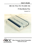
Counter (Encoder) Input
Specifications & Installation Guide
July 27, 2011
Configuration:
___PCI-CTR05 (5 Counters) P/N
___PCI-CTR10 (10 Counters) P/N
___PCI-CTR20 (20 Counters) P/N
___USB-4301 (5 Counters) P/N
777 Zapata Drive Fairborn, OH 45324 USA 888.707.4852 Fax: 937-318-2445
E-mail: [email protected]
www.laserlinc.com
1
Contents
1 SPECIFICATIONS ........................................................................................................................... 3
2 INSTALLATION .............................................................................................................................. 4
2.1 INSTALLATION PROCEDURE USB-4301............................................................................................ 4
2.2 INSTALLATION PROCEDURE PCI CTR CARD ................................................................................... 6
3 WIRING PROCEDURE................................................................................................................... 8
3.1
3.2
3.3
3.4
CTR05 WIRING PROCEDURE........................................................................................................... 8
CTR10 WIRING PROCEDURE......................................................................................................... 10
CTR20 WIRING PROCEDURE......................................................................................................... 12
USB-4301 WIRING PROCEDURE .................................................................................................... 14
4 SOFTWARE CONFIGURATION ................................................................................................. 16
4.1 CREATE LENGTH MEASUREMENT.................................................................................................. 16
4.2 CREATE SPEED/RATE MEASUREMENT ........................................................................................... 18
4.3 VERIFY ENCODER INPUT USING OSCILLATOR OUTPUT.................................................................. 21
777 Zapata Drive Fairborn, OH 45324 USA 888.707.4852 Fax: 937-318-2445
E-mail: [email protected]
www.laserlinc.com
2
1 Specifications
• Compatibility: 5V/TTL
• Clock input frequency: 6.8 MHZ max (145 nS minimum period)
• Clock input minimum pulse width: 70 ns
• Voltage for low input: -0.5 V min, 0.8 V max
• Voltage for high input: 2.2 V min, Vcc max
• Crystal oscillator frequency: 10 MHz
• Frequency accuracy: 50 ppm
777 Zapata Drive Fairborn, OH 45324 USA 888.707.4852 Fax: 937-318-2445
E-mail: [email protected]
www.laserlinc.com
3
2 Installation
2.1 Installation Procedure USB-4301
This section assumes that the PCI TLAser400 Interface Card and Total Vu software are installed, a
scanner is connected and calibrated, and a measurement is defined. Refer to the Total Vu Operator’s
Manual for further details.
1) Install the InstaCal Software by browsing to the InstaCal folder in “C:\Program
Files\LaserLinc\Total Vu” or the Total Vu CD “\InstalCal” and executing
“D:\InstaCal\icalsetup.exe”.
2) Connect the USB cable from the USB-4301 to any PC USB connection.
3) Windows will detect a new Plug-N-Play device. Wait until the message says “Ready to Use”.
4) Execute the InstaCal software. INSURE THE USB-4301 IS DETECTED BY INSTACAL.
5) IMPORTANT - Double click on the entry USB-4301
Select “Clock Speed” pull-down menu, and change to 1 MHz, click “OK”.
Select 1 MHz Clock Speed
6) Exit InstaCal.
777 Zapata Drive Fairborn, OH 45324 USA 888.707.4852 Fax: 937-318-2445
E-mail: [email protected]
www.laserlinc.com
4
7) Disable USB Power Management
Enter Windows Device Manager - Select START\CONTROL PANEL\SYSTEM, Select HARDWARE
tab, select Device Manager, select Universal Serial Bus Controller
Select USB Root Hub, Power Management tab – uncheck “Allow the computer to turn off this device
to save power” (If there are more than one USB ROOT HUBS ,repeat for each occurrence )
777 Zapata Drive Fairborn, OH 45324 USA 888.707.4852 Fax: 937-318-2445
E-mail: [email protected]
www.laserlinc.com
5
2.2 Installation Procedure PCI CTR card
This section assumes that the PCI TLAser400 Interface Card and Total Vu software are installed, a
scanner is connected and calibrated, and a measurement is defined. Refer to the Total Vu Operator’s
Manual for further details.
1) Power down the PC.
2) Install the PCI CTR-05/10/20 into any available PCI slot in the PC.
3) Connect the cable from the PTRB to the PC backpanel PCI CTR-05/10/20 connector.
4) Restart computer and boot Windows.
5) Windows will detect a new Plug-N-Play device, place the Total Vu CD into the CD drive and let
Windows automatically find the driver. Follow the Window’s prompts until finished.
6) Install the InstaCal Software by inserting Total Vu CD and executing “D:\InstaCal\icalsetup.exe”.
7) After rebooting, execute the InstaCal software; INSURE THE PCI CTR-05/10/20 CARD IS
DETECTED BY INSTACAL, then exit.
8) Execute Total Vu.
9) Select the Configure/Full Configuration screen and verify the appropriate icon; CTR-05/10/20
icon now appears.
777 Zapata Drive Fairborn, OH 45324 USA 888.707.4852 Fax: 937-318-2445
E-mail: [email protected]
www.laserlinc.com
6
For the CTR05 connect the 37 pin connector ribbon cable from the CTR05 card to the provided
breakout box.
For the CTR10 connect one 37 pin connector ribbon cable from the CTR10 card’s external port and to
one of the breakout boxes provided. Connect the other 37 pin connector ribbon cable from the port on
the inside of the computer on the front of the card, through the back of an empty PCI card slot and to
the other breakout box provided.
For the CTR20 read this entire set of directions before you proceed. The connection on the back of the
PC is reversible and will destroy hardware if reversed. If you stretch the cable out you will find a
connector at each end and a connector at the center. The connectors at each end connect to your
breakout box and are not reversible. These can be connected in any order. The connector in the center
is shown in Figure 1 connected to the card. There are two arrows labeled FD0274 and FD8491. These
arrows must be aligned in order for the ribbon cable to be connected properly.
1. Figure 1 Connector for CTR20 card looking up
777 Zapata Drive Fairborn, OH 45324 USA 888.707.4852 Fax: 937-318-2445
E-mail: [email protected]
www.laserlinc.com
7
3 Wiring Procedure
3.1 CTR05 Wiring Procedure
The CTR05 has 37 output pins as shown in Figure 2 on the next page. The counter (encoder) inputs for the
five (5) counters are signified as CTR1CLK through CTR5CLK. Select one of your counters and wire the
signal wire to its respective input pin. Then connect the ground wire to GND (pin 11). For my example I
chose counter 1 (CTR1CLK) with Figure 3 giving me pin 36 as my signal input pin. Therefore I have my
signal wire running to pin 36 and my ground wire running to pin 11 as shown in Figure 2.
Signal
Wire
Pin (36)
Ground
Wire
Pin (11)
2. Figure 2 Counter Input wiring for Counter One (1)
777 Zapata Drive Fairborn, OH 45324 USA 888.707.4852 Fax: 937-318-2445
E-mail: [email protected]
www.laserlinc.com
8
3.
Figure 3 CTR05 Pin Out
777 Zapata Drive Fairborn, OH 45324 USA 888.707.4852 Fax: 937-318-2445
E-mail: [email protected]
www.laserlinc.com
9
3.2 CTR10 Wiring Procedure
The CTR10 has two breakout boards each using 37 output pins as shown in Figure 5 on the next page. The
counter (encoder) inputs for the ten (10) counters are divided between two sets of five (5) counters. The
inputs for the counters on board A are signified as CTR1CLK_A through CTR5CLK_A. The inputs for
counters on board B are signified as CTR1CLK_B through CTR5CLK_B. Select one of your counters and
wire the signal wire to its respective input pin. Then connect the ground wire to GND (pin 11). For my
example I chose counter 1 on board A (CTR1CLK_A) with Figure 5 giving me pin 36 as my signal input
pin. Therefore I have my signal wire running to pin 36 and my ground wire running to pin 11 as shown in
Figure 4.
Signal
Wire
Pin (36)
Ground
Wire
Pin (11)
4. Figure 4 Counter Input wiring for Counter One (1) on Board A
777 Zapata Drive Fairborn, OH 45324 USA 888.707.4852 Fax: 937-318-2445
E-mail: [email protected]
www.laserlinc.com
10
5.
Figure 5 CTR10 Pin Out
777 Zapata Drive Fairborn, OH 45324 USA 888.707.4852 Fax: 937-318-2445
E-mail: [email protected]
www.laserlinc.com
11
3.3 CTR20 Wiring Procedure
The CTR20 has 100 output pins as shown in Figure 7 on the next page. The counter (encoder) inputs for
the twenty (20) counters are divided between four groups (A through D) of five (5) counters. The inputs
for group A are labeled CTR1CLK_A through CTR5CLK_A. The inputs for group B are signified as
CTR1CLK_B through CTR5CLK_B. The inputs for group C are labeled CTR1CLK_C through
CTR5CLK_C. The inputs for group D are labeled CTR2CLK_D through CTR5CLK_D. Select one of
your counters and wire the signal wire to its respective input pin. Then connect the ground wire to any
GND. For my example I chose counter 2 on group A (CTR2CLK_A) with Figure 7 giving me pin 5 as my
signal input pin. I also chose the GND on pin 8. Therefore I have my signal wire running to pin 5 and my
ground wire running to pin 8 as shown in Figure 6.
Signal
Wire
Pin 5
6. Figure 6 Counter 2 on group A input pins 5 and 8
777 Zapata Drive Fairborn, OH 45324 USA 888.707.4852 Fax: 937-318-2445
E-mail: [email protected]
www.laserlinc.com
12
Ground
Wire
Pin 8
7.
Figure 7 CTR20 Pin Out
777 Zapata Drive Fairborn, OH 45324 USA 888.707.4852 Fax: 937-318-2445
E-mail: [email protected]
www.laserlinc.com
13
3.4 USB-4301 Wiring Procedure
The USB-430 has 56 output pins as shown in Figure 9 on the next page. The counter (encoder) inputs for
the five (5) counters are signified as INP1 through INP5. Select one of your counters and wire the signal
wire to its respective input pin. Then connect the ground wire to GND. For my example I chose counter 1
with my input being INP1 Therefore I have my signal wire running to INP1 and my ground wire running
to GND as shown in Figure 8.
Signal
Wire
INP1
Ground
Wire
GND
8. Figure 8 USB-4301 Input for counter 1 (INP1 and GND)
777 Zapata Drive Fairborn, OH 45324 USA 888.707.4852 Fax: 937-318-2445
E-mail: [email protected]
www.laserlinc.com
14
9. Figure 9
USB-4301 Pin Out
777 Zapata Drive Fairborn, OH 45324 USA 888.707.4852 Fax: 937-318-2445
E-mail: [email protected]
www.laserlinc.com
15
4 Software Configuration
4.1 Create Length Measurement
Identify which counter to which you have connected
your signal wires as performed above in section 3.
Open Total Vu Configure (Ctrl-C) and double click on
‘Measurements’ icon. Double click on ‘Add Counter
Measurement’ as shown in Figure 10.
10. Figure 10 Measurements window
This will bring up the ‘Add Counter Measurement’
window as shown in Figure 11. In the first list select
the device you will use to collect your encoder pulses
(e.g. CTR20-1).
This will bring up the list of counters for your
selected device. If you are using a CTR10 or a CTR20
the counters are grouped in two groups (A and B) or
four groups (A, B, C and D) respectively. If you plan
to make a rate measurement out of this encoder input,
ensure that there are two counters available in your
desired letter group. Next select one of these
identified counters.
As soon as this selection is made Total Vu will tell
you which pin your signal wire should be hooked up
to.
11. Figure 11 Add Counter Measurement
Window
If this pin number confirms your selection push
‘Next’.
777 Zapata Drive Fairborn, OH 45324 USA 888.707.4852 Fax: 937-318-2445
E-mail: [email protected]
www.laserlinc.com
16
The next window configures your selected counter
to your encoder source as shown in Figure 12. In
the first drop down menu select the unit that you
would like your encoder readout to display in. This
can be any unit of your choosing and does not
pertain to your encoder source.
In the next blank you will be required to calculate
how many encoder pulses will be generated by your
signal source for each of your selected unit above.
If you only know pulses per meter (17539
pulses/meter) and yet you want your readout in
feet, do a simple conversion. (x 1/3.281 feet/meter
= 5346 pulses/foot).
Next select how many decimal places you want
displayed on your encoder length readout. Select
this number in the drop down menu under
‘Resolution’.
12. Figure 12 Configure Encoder
Now push ‘Next’.
Our final window allows us to set the measurement
name as shown in Figure 13. Come up with a
unique yet self-explanatory name representative of
the encoder measurement created. This name will
be displayed next to your measurement value in
any windows or measurement displays. Insert this
name in the blank under ‘Measurement Name’.
With this name inserted select ‘Finish’.
13. Figure 13 Measurement Name
777 Zapata Drive Fairborn, OH 45324 USA 888.707.4852 Fax: 937-318-2445
E-mail: [email protected]
www.laserlinc.com
17
4.2 Create Speed/Rate Measurement
This will require the addition of a time
measurement. This is because all rates are defined
on a per time measurement (e.g. feet per second).
Open up the Total Vu Configure window (Ctrl –
C) and double click on the ‘Add Time
Measurement’ icon.
This will bring up the ‘Add Time Measurement’
window as shown in Figure 14. In the top list
select the same device you used in section 4.1 (e.g.
CTR20-1).
If you are using a CTR10 or a CTR20 the counters
are grouped in two groups (A and B) or four
groups (A, B, C and D) respectively. The next step
requires that you select a counter in the same letter
group as the counter used in section 4.1. In this
example both of my selected counters are in group
‘A’. Here I selected ‘Counter 4A’ as I had selected
‘Counter 1A’ in Section 4.1.
14.
Figure 14 Select Counter
Now push ‘Next’
The next screen requires you to select a ‘Source
Frequency’. Your selection depends on how
precise you want your rate measurement to be.
This will determine how many decimal points
you can accurately display at a respective update
frequency. A selection of ‘1 KHz’ or ’10 KHz’ is
recommended for most applications.
Now select ‘Next’.
15. Figure 15 Source Frequency
777 Zapata Drive Fairborn, OH 45324 USA 888.707.4852 Fax: 937-318-2445
E-mail: [email protected]
www.laserlinc.com
18
Now decide what rate measurement base you
desire. (e.g. Feet/second or Feet/Minute). Select
this timer unit in the top drop down menu as
shown in Figure 16.
Do not put anything in or modify the ‘Pulses Per
Second’ field as this will be updated
automatically depending on your clock rate and
unit selection.
For your timer ‘Resolution’ select 5, 3, or 2 for
timer units of ‘Hours’, ‘Minutes’, or ‘Seconds’
respectively.
Click ‘Next’ to continue. On the next screen
enter as the measurement name your chosen
timer unit (e.g. Seconds). Click ‘Finish’.
16. Figure 16 Timer Configuration
Double click on ‘Add Functional Measurement’
to bring up the ‘Add Functional Measurement’
window as shown in Figure 17. Select the
Operation ‘Rate’.
Click ‘Next’ to continue.
17. Figure 17 Select Rate
777 Zapata Drive Fairborn, OH 45324 USA 888.707.4852 Fax: 937-318-2445
E-mail: [email protected]
www.laserlinc.com
19
For ‘Operand A’ select your encoder length
measurement selected in section 4.1 above.
For ‘Operand B’ select your timer unit as
specified in Figure 16 above.
Click ‘Next’ to continue.
On the next screen select the radio button next
to ‘Continuous’ and click ‘Next’
18. Figure 18 Select Operands
In the space under ‘Number to Average’
insert a value of at least ‘10’. This will
ensure your displayed measurement value is
not affected by the resolution of your
encoder output.
If you would like a continuous and
instantaneous rate value to be displayed
click the checkbox next to ‘Use Running
Average’.
In the dropdown menus under ‘Resolution’
select how many decimal places you want
displayed on your Speed/Rate value.
Click ‘Next’ four times to continue until
you reach the ‘Measurement Name’
selection. Come up with a unique yet self-explanatory name representative of the encoder measurement
created. This name will be displayed next to your measurement value in any windows or measurement
displays. Insert this name in the blank under ‘Measurement Name’. With this name inserted select
‘Finish’.
777 Zapata Drive Fairborn, OH 45324 USA 888.707.4852 Fax: 937-318-2445
E-mail: [email protected]
www.laserlinc.com
20
4.3 Verify Encoder Input using Oscillator Output
This section is used to verify that your configured Counter (Encoder) Input is working correctly. This is
only needed as a troubleshooting step to identify whether the error lies in the signal source or the Counter
Input configuration.
In the pin out diagrams (Figure 3, Figure 5, Figure 7, and Figure 9) find an OSC OUT output for your
respective input device. This output will be used as a signal for your counter input.
For the CTR05 use OSC OUT (pin 30). Run a wire from this pin to your counter input pin. For my
example I chose counter one (1) with the input being pin 36. Therefore I have a wire running from pin 30
to pin 36 as shown in Figure 19.
For the CTR10 use OSC OUT_A or OSC OUT_B both pin 30 for their respective board. Run a wire from
this pin to your counter input pin. For my example I chose counter one (1) on board A with the input being
pin 36. Therefore I have a wire running from pin 30 to pin 36 as shown in Figure 19.
OSC OUT
Pin 30
INPUT
Wire
Pin 36
19. Figure 19 Oscillator Output test for CTR05 and CTR10
777 Zapata Drive Fairborn, OH 45324 USA 888.707.4852 Fax: 937-318-2445
E-mail: [email protected]
www.laserlinc.com
21
For the CTR20 use OSC OUT_A (pin
22). Run a wire from this pin to your
counter input pin. For my example I
chose counter one (1) on group A with
the input being pin 5. Therefore I have a
wire running from pin 22 to pin 5 as
shown in Figure 20.
20. Figure 20 Oscillator Output test for CTR-20
For the USB-4301 use OSC. Run a wire
from this pin to your counter input pin.
For my example I chose counter one (1)
with the input being INP1. Therefore I
have a wire running from OSC to INP1
as shown in Figure 21.
21. Figure 21 Oscillator Output test for USB-4301
777 Zapata Drive Fairborn, OH 45324 USA 888.707.4852 Fax: 937-318-2445
E-mail: [email protected]
www.laserlinc.com
22