1
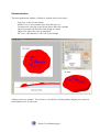
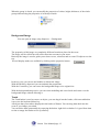
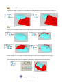
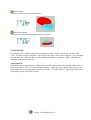
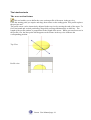
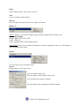
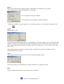
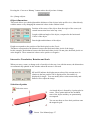
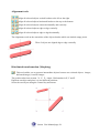
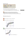
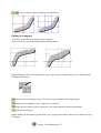
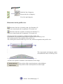
Stenza
User Manual
Version :- 0.2e
Date : November 2003
Stenza User Manual page 1
Copyright © 2001-2003 PICASOFT SA ® - All rights reserved
The content of this manual and software describe is protected by the international laws of the
author’s right. Neither the software nor the manual can be reproduced, saved or transmitted or
otherwise, without prior written permission of PICASOFT sa (11 March 1957 law and 3 of July
1985 law on the author’s right).
Limitation of guarantee and responsibility
Even if the programme described in this manual, being well tested, neither PICASOFT nor his
suppliers can offer a guarantee, implicit or clear, on its qualities, its performances or its capacity in
satisfying the user needs. The user assumes the risks of the utilisation and its possible
consequences. In any case, PICASOFT or its suppliers cannot be responsible for some direct or
indirect consequences, from whatever nature it can be, resulting from a defect of the programme or
in the manual, or from the utilisation, even if they were or were not told about the possibility of that
sort of injuries. However the buyer has the right to the legal guarantee, only in the case and in the
measure we can apply the legal guarantee, not withstanding all exclusions or limitations.
More, PICASOFT keeps the right to modify the product characteristics or the content of its
documentation without telling the users.
By the use of that product you accept the above clauses.
PICASOFT®, the logo PICASOFT, and the names and the logo’s Mayka™, Maquette Volume™,
Stenza™ are trade marks of PICASOFT sa.
Microsoft™, Windows™, logo Windows™, are trademarks of Microsoft Corporation.
All the other products quoted in the manual are trademarks:
AutoCAD & DXF are trademarks of AutoDesk.
Picza is a tradename of Roland DG Corp
Adobe Photoshop & Illustrator are trademarks of Adobe Systems Inc.
All the other products or marks quoted in this manual are acknowledged trademarks of their
respective owners.
E&OE
English Stenza Manual :- Patrick Thorn November 2003
Stenza User Manual page 2
Introduction
Stenza is a software developed for 3D artistic creation.
Its special technology makes it possible to utilise a range of innovating tools.
The way Stenza works is very different from traditional CAD software, as it allows you to be very
creative to :-
Create low reliefs starting from simple photographs
-
Give relief to your Logos; Jewels, medals…
-
Improve and edit 3D digitised objects
-
Place/wrap reliefs on shapes and objects
-
Deform existing objects
-
Convert 2D logotypes into 3D logos
-
etc.…
It is not necessary to be a CAD specialist to utilise this programme, but the software has many tools
that you need to discover their principles to gain the full potential of Stenza. Thus, we recommend
you read the following pages as a guide to understanding these principles.
We are sure that Stenza will enable you to model virtually all of your ideas.
So now it is over to you to play and create !.
The Technology
Stenza uses the concepts of greyscale technology:
A bitmap image consisted of white, black and grey pixels, that are converted by Stenza into groups
of 3D points.
Each pixel of the image is transformed into a point whose X and Y coordinates are defined by the
position of the pixel in the image. The Z height of the point is given by the level of grey of each
pixel.
The scale of levels are user defineable with the tools of Stenza.
To create and modify 3D objects in Stenza means, therefore, to create and manipulate images.
The interactivity of creation as well as the fineness of detail is made possible with this technology.
Whereas a CAD adapted software cannot easily achieve creations of such complex forms.
Stenza User Manual page 3
Installation
You should have a Picasoft CD containing the installer for the software.
A software protection key is provided in the box with this handbook. The software functions under
Windows 98se, NT, 2000, XP, although we recommend the latest 2000 or XP versions of Windows.
Memory is a key factor for quick image manipulation, therefore, a fast computer with at least
512Mb RAM or more will be preferred. The 3D views of Stenza utilise OpenGL so any additional
graphics support will make things work faster.
Insert CD in the reader of your PC, it should auto-start. If not open the CD.
This contains:
-
The installer for the software
-
Example files
-
Documentation
Click on the icons of your choice and follow the on screen instructions.
Protection
The Stenza software is protected against illegal copying and requires a user licence to be purchased
for full use. Initially you can use Stenza for 30 days from installation so you can try it before
buying your licence, or whilst you are waiting for your licence to be supplied. When you purchase
your user licence, a protection key sequence will be given to you. This key sequence will be
provided for the computer you are using as a single licence and will be needed to operate the
software and to gain product support.
When you launch Stenza the first time you will be prompted to enter your details. If this is
cancelled you can select the register function User Code from the "?" menu, or click the register
button on the main start up window when the software is launching:
Enter your licence/serial number (this the one on your licence document).
Validate this by clicking on OK, then exit Stenza using the Exit under the File menu. When you
next launch Stenza, your authorisation will be taken into account.
Note: You need to install Stenza and enter the User Code under the administration access of
Windows. Stenza is not designed to be a server multiuser driven application.
Stenza User Manual page 4
Stenza interface
The main application window of Stenza is separate into several zones:
-
Top View, a plan of your design
Profile View, a cross-sctional view from the top view
Creation tools, selecting a specific tab shows the tools available
Object list, where all the parts of the design are listed
Object size, where the sizes are displayed
3D View, a full interactive 3D view of your design
All these zones are editable. You can the re-size them by clicking and by draging your cursor on
the boundary lines of each zone.
Stenza User Manual page 5
The Views
Top View
The top view is in common with the dimensions of the document.
You can view the document properties.
You can visualise the objects in grey level mode or in relief mode with this button.
You can select and move in X and Y:
- the control points
- the objects
- the selection zones
- the object manipulator
- the profile selection which is represented by a horizontal arrow by default
Profile View
Display the profile with equal proportions in X, Y, Z
Fit the profile in the view.
This cursor adjusts the view of profile but does not affect the objects.
The window of profile has various selected behaviours according to the type of objects.
The object type selected automatically imposes the mode of visualisation of the profile view.
Stenza User Manual page 6
In Placement, Modelling, Text and Library modes
The profile view shows the cutting plane of all the objects of the scene according to the profile
selection arrow located in the top view.
The length of the profile window is proportional to the length of the arrow.
The profile arrow can be interactively adjusted in the top view by moving the ends of the arrow.
In this mode you can adjust the thickness and heights of the objects.
Left Click and drag on the object profile to modify the thickness
Right Click and drag on the object profile to modify the height
In Deformation mode
The profile view shows the sections of all the objects of the scene according to the arrows location
in the top view.
The length of the profile window is proportional to the length of the arrow.
The profile arrow can be interactively adjusted in the top view by moving the ends of the arrow.
In this mode, the deformation control points of the surface appear and allow the Z heights to be
deformed.
Stenza User Manual page 7
In Vectorial Curve mode
The profile of the filled path is displayed and is editable.
You can select, add and move the control points of the profile.
In the higher part of this window, you can
adjust the profile view with the slider. This
does not change the dimensions of the
object. Other icons appear according to the
curve tools used.
The library button gives you access to a
library of profiles.
See the Curve tab for the tools available to
you.
3D View
This window displays your model using OpenGL technology.
The 3D tool bar
Rotate view tool
With other tools selected, you can rotate the view using the right mouse button.
Pan tool to move around the view.
Zoom tool. Drag the mouse up or down to adjust the view.
Right view.
Front view.
Top view.
Fit object to view.
Switch displays between object only and object with the Z0 plane.
This cursor changes the precision of the view of the object.
Note the response time of your computer obviously depends on this adjustment, but the actual
model is not affected by the quality of the view.
Stenza User Manual page 8
In this view you can see the corresponding position of your mouse by a small red arrow that
corresponds to the position of your mouse in the top view.
Stenza User Manual page 9
The object list
The object list contains several object types:
Scene :
Is a file which contains all the objects that are in the current design. It is presented in hierarchical
tree form called a list.
Each object can be arranged into groups and each group be arranged into another group etc?
The scene; the objects and the groups have properties of colour, mode, placement and editable
dimensions.
The scenes dimensions remain in the properties of each document. To select an object in the list,
click on its name.
You can move the objects in the list to re-elect them (Drag with mouse), change their colours, to
make them inactive invisible, to delete them. ?
To adjust the properties right click on the name of the object in the list.
Image objects
There are two types of image objects:
Bitmap images
Bitmap images in levels of gray (grayscale). These images can be worked on in the modes:
placement, deformation, modelling.
They can come from:
The library
Importing a bitmap file
By converting of a vectorial image into bitmap.
Creation of your own
Stenza User Manual page 10
To create a new image, click the icon.
Each image appears in the scene, and is selectable in the list or the top window.
The name of the image in the appears list . You can rename the image by right clicking on the name
in the list.
Note: If the name appears between parenthesis, it no longer acts as a bitmap image, it acts a
vectorial image.
It appears as a grid of points in Stenza. The size in pixels is displayed on the right of the list. The
thickness of this grid is chosen by default. You will have to define the height, thickness and mode
of placement with appropriate tools.
The colour of the grid is chosen in a random manner to the creation, you can modify its colour
when right clicking the object in the list.
Vectorial images
These images have certain design parameters that are still editable.
They can come from:
- the creation of a traced object
- the deformation of a bitmap image in deformation mode
- the inlination of an object in placement mode.
In the list their name appears between brackets.
Their design properties are editable.
The vectorial images can be worked on in creation mode.
The modelling tools are not available if you wish to keep their design parameters. You will have to
convert vectorial images into bitmap images in order to be able to use the modelling mode.
The vectorial images are handled in the list like the bitmap images.
The groups
This tool creates a group in the list.
If several images are selected, they will be automatically placed in the group.
You can make groups of groups.
A group can be to amalgamate in one image with this function
The modelling tool is not available on the groups if you do not amalgamate them.
The group is open and closed buy clicking the small + or – icon in the list.
When the group is open you can work on the objects included.
Stenza User Manual page 11
When the group is closed, you can modify the properties of colour, height, thickness, of the whole
group without losing the properties of each object inside.
Background Image
You can open an image using Import as > Background
The properties of this image are completely different from those placed in the scene.
The image will be visible but will not be taken into account in your scene.
Basically the image is used to guide you to draw curves, selections and to create 3D objects over the
top.
Several display modes are available by clicking on the properties button.
In the top view you can use the handles to deform the image.
With the Shift key depressed you can maintain the proportions
With the Control key you can restore the background image to its original size.
With the background image active you can select modelling and curved tools and create over the
background image without affecting it.
Trash
The Trash basket is used to remove an object, you can drag it into the basket, click on trash basket
icon or use the keyboard delete key.
All objects that you trash are displayed in the basket of Stenza. You can drag them back into the
scene if you change your mind.
You can delete them permentally by emptying the basket: right click on basket. It is good from time
to time to empty the basket to free up memory.
Stenza User Manual page 12
List of objects
Moving in the list
To move an object in the list, select the object and then click either
object in the list.
or
, you can also drag the
Mode of placement tools
Mode of placement
These 4 buttons define the mode of placement of each object in the scene. They make it possible
for each object to be placed compared to other objects.
To use these tools, it is necessary to select the object and press on the button which corresponds to
the mode that you wish to define. In the list, the placement mode is visualised by an icon in front of
the name of the object.
Placement icons
Principle :
Stenza processes the objects of the scene list one after another, from top to bottom.
The objects are draw following the arrow.
In this example :
round is in union mode with ellipse and cube
object4 is in addition with ellipse, cube and round
The order of the objects in the list is therefore very significant to obtain the correct results which
you wish to obtain.
Stenza User Manual page 13
Absolute mode
Each object (image or group) does not take into account the other objects located before in the list.
Addition/Subtraction mode
Each pixel of is added to all the pixels of the objects located before it in the list.
In this example, the 3D result is identical although the colours do not display the same thing.
The subtraction is the objects in addition with negative thickness entered in the dialog.
Stenza User Manual page 14
Union mode
The parts of the object are joined together.
Intersection mode
The area of the parts shared by both objects is retained.
.
Visible/Invisible
Each object can be made invisible, but its placement mode of will be taken into account in the
scene. To make an object invisible: right click on the name of the object in the list. The placement
icon becomes red. In the profile view, it is displayed hatched. To make it visible: right click on
the name of the object in the list.
Active/inactive
Each object can be made inactive, which means invisible and not taken into account in the scene, as
if the object did not exist. To make an object inactive: right click on the name of the object in the
list or click on icon, the placement icon becomes white. To make it active: right click on the name
of the object in the list or click on icon.
Stenza User Manual page 15
The interface tools
The cross section feature
This tool enables you to define the cross section profile of the arrow in the top view.
Click the starting point you require and drag, then release on the ending point. This profile replaces
the previous one.
The profile arrow can be interactively adjusted in the top view by moving the ends of the arrow. To
force horizontal and vertical positioning, drag while pressing simultaneously on shift key. The
length of the profile window is proportional to the length of the arrow. When your mouse moves in
the profile view, the blue point which appears on the feature in the top view indicates the
corresponding position.
Top View
Profile view
Stenza User Manual page 16
The Interface toolbar
Zoom tool. Click Zoom for +. Press ALT key and click for Zoom Pan mode
Profile Arrow
Undo
Redo
Fit Scene to Screen. With CTRL key, fit the selected object to screen.
CTRL + F key, fit the selected object to screen
Snap to grid
Grid. Change the grid parameters
3D view update active / inactive
Display mode greyscale or colour relief
Control tool
Transfer design directly to MAYKA if installed on your computer
Help
Control tool
Each time you to click on this icon, you show or hide the object manipulator called the Control
tool.
This tool enables you to manipulate the selected objects: images, groups, layouts
and control points of layouts in relation to the center of the control tool circle.
To move the Control tool center, right click the mouse where you want it to be in
the top view. With this tool you can change the characteristics of the object. The center and edge
handles can be moved freely or with the Snap active, you can snap the positions to the grid
Stenza User Manual page 17
Blue Point : rotates the selected object.
Red Point : scales the selected object in the red direction.
Green Point : scales the selected object in the green direction.
Yellow Point : scales all 3 dimensions proportionally. With the ALT key depressed, only the object
is scaled in X and Y, but the Z height is not.
Control remembers the last angular position of the image whist it is active.
To reinitialise the control back to horizontal without moving the object, click the control icon
in the tool bar, off then on again. The rotation angle is set back to zero.
Stenza User Manual page 18
The menus
File
New
Creates a new Scene.
You must define the size and the resolution in the following window.
Width and height are dimensions in units of the Scene
Width and height are dimensions in number or pixels of the Scene
The resolution defines the number of pixels per unit.
Method describes the type of grid of points:Planar defines a flat X, Y, Z grid.
Cylindrical defines a rolled up grid on a diameter equal to the
length/PI(3.142).
Symmetrical defines two identical planar grids, a top and bottom the same. This mode enables you
to make completely symmetrical models.
Always choose to make your model as close to the size of the finished object with the resolution
you require. Excessive sizes will demand more memory from your computer as this is directly
related to the number of points in the scene.
Stenza User Manual page 19
Open
Opens Stenza Scenes. (One scene at a time)
Save
Saves a complete Stenza Scenes
Save as
Saves an open complete Stenza Scene under a new name.
Import as
Object : Allows you to import images, grids of points, digitised files into the scene.
Compatible formats
Images: BMP, JPEG, PNG, GIF
Curves : EPS, AI
Grids : MAYKA MVG, PIX (Roland Picza)
Background: Allows you to import an imageto be used as a template to work over. This image is
not a 3D image in the scene.
Export
You can export in several object types:
Pictures
Image pictures of 256 grey levels,
You can export all the scene
You can export a selected part of the scene
You can adjust the images resolution.
You can improve the smoothness with anti-aliasing
Stenza User Manual page 20
Mayka
Mayka (by Picasoft) is the milling software which allows you machine your creation.
The resulting grid contains upto 64000 levels in height.
You can adjust the images resolution.
You can improve the smoothness with anti-aliasing
If Mayka is installed on your computer you can directly transfer your design by clicking this icon.
Model
Model DXF or STL
The grid of points Stenza generates are very significant. You must compress it so as to decrease the
number of facets in your model and to obtain a reasonable file size. When you use the compression
slider, Stenza indicates the number of triangles which you will generate. Close will close any open
faces in file.
Anti-aliasing makes it possible to smooth certain vertical faces to remove the effects that can
deteriorate parts of the object.
Video
This outputs a small video movie of the 3D viewed object being rotated.
Note a large frame size and frames per second will make very large movie files
Quit
Quit the application and check if you want to save the object.
Stenza User Manual page 21
Edit
Undo/Redo
The function moves back or forward over the edited operation just performed.
Several levels of undo are available.
Cut/Copy
Standard window’s function that can be used on objects and in dialog boxes..
Copy to Library
Places a copy of the selected object into the selected library.
Copy scene to Library
Places a copy of the whole scene into the selected library.
Paste
Standard window’s function that can be used on objects and in dialog boxes.
Delete
Deletes the selected object.
Select all
In Placement mode the selection is done on the objects.
In Deformation mode, the selection is done on the control points.
In Curve mode, the selection is done on the control points of the curves according to the tool
selected.
In Modelling mode, the selection is done on the pixels.
Stenza User Manual page 22
Deselect
Cancels selections.
Inverse selection
In Modelling mode, select only the pixels which were not selected previously.
Appearence
Enables you to modify look of Stenza's windows
Document properties
See File/New
Display
Normal/Cylindrical/Symmetrical
The scene displayed according to different modes, see File/New.
This only effects the view, not the actual design.
Wireframe
Changes the 3D view from shaded to wireframe.
Grid
The grid is a visual reference to place or draw elements in the top view and the profile view. You
can adjust its spacing, make it visible or not, and magnetic or not for snapping to.
To make it visible or invisible, you can use the icon
in the tool interface.
To make it magnetic or non-magnetic, you can use the icon
Stenza User Manual page 23
in the tool interface.
Show/Hide cursor in 3D view
You can have your cursor position in the top view displayed in the 3D view as well.
Relief
Equivilent to the interface button
that displayes coloured or greyscale top view.
Simplified mode
Suppresses part of the interface so only the basic tools are available.
Expert mode
Displays all the menus and interface options
Window
Rearrange windows
Replaces the windows in the standard default position
Top view fit screen
Places the top view as the whole screen
3D view fit screen
Places the 3D view as the whole screen
Normal view
Returns from Top or 3D view to the view layout you last adjusted
Info
User code
User code, provided by your supplier, can be entered to allow you to use a full licence.
About …
General Information about Stenza
Stenza User Manual page 24
The keyboard short cuts
Placement
CTRL + drag an object = To duplicate the object
CTRL + Shift + drag an object = To duplicate the object, horizontal, vertical or 45° Shift + drag an
object = To move the object vertically horizontally, or 45°
CTRL Z = To Undo last action
CTRL Y = To Redo last action
Arrow keys = Moves the selected object by one pixel per key press
CTRL + Click = Allows multi selection of objects in the top view and the list. Each click adds an
object to the selection, clicking again unselects.
Shift + Click = Multi selection of the objects in the list. The click adds all the objects in the list
located between the current selection and the object clicked.
CTRL F = fits the view of a selected object
Curves
Shift + drag a point/handle = To move the point/handle vertically, horizontally, or 45°
Stenza User Manual page 25
The tools of modelling
The tab above each box gives you access to several working methods and their associated tools.
Placement mode
This mode which enables you to place and manipulate your objects in the top view..
Representation of the objects
There are several types objects, see Image objects
In the list, only the name of the Bitmap images are not between brackets.
When an object is selected, in the top view, the object type is shown in the following way:
Bitmap object
Object with curves
Deformed object
Stenza User Manual page 26
Pressing the ‘Convert to Bitmap’ button makes the object into a bitmap.
See § Image objects
Object dimensions
This mode allows you edit height and the thickness of the objects in the profile view, either directly
with the mouse or by changing the numerical values in the window below.
Position of the center of the object from the origin of the scene (red
central intersection lines in the top view).
Length, width and angle of the object, compared to the horizontal.
Colour of the object.
Base height and thickness of the object.
Height corresponds to the position of the black pixels on the Z axis.
Thickness corresponds to the distance between the black and white pixels of the image.
In this example, the thickness between the black and white pixels is 4 mm plus, the black pixels are
at the height 0. These numerical values can be positive or negative.
Interactive Translation, Rotation and Scale
When you move, rotate, or change scale of an object in the top view with the mouse, the dimensions
are automatically updated in this window when the mouse is released.
dX and dY indicate the displacement values of the current move in
relation to the last position. DS is displayed for Size and dA is
displayed for Angle. You can modify these values numerically and
Stenza will re-adjust the image.
Selection of points
Selection arrow.
A selected object is framed by 8 points plus its
center. These points indicate the included
zone of the object and they are permanently
recomputed.
You can use them to force their positions onto
the magnetic grid.
Stenza User Manual page 27
Alignement tools
Align all selected objects vertical borders to the left or the right.
Align all selected objects horizontal borders to the top or the bottom.
Align all selected objects centers horizontally and vertically.
Align all selected objects edge to edge vertically.
Align all selected objects edge to edge horizontally.
The alignments work on the extremities of the objects borders which can include empty pixels.
These 2 objects are aligned edge to edge vertically.
Distributed transformation (Morphing)
This tool enables you to generate intermediate objects between two selected objects: images,
deformed images, vectorial images.
The position takes into account: X; Y; Z; Angle; Deformation in X, Y and Z.
Duplicate an object and place it in two different positions.
Select the two objects using the Control key and mouse.
Stenza User Manual page 28
Click the
button and indicate the numbers copies.
This result gives you 3 intermediate images.
You can make a group of all the selected objects if you
click on the group icon in the list
The duplicates take account of the height as well.
In the case of morphing vectorial images, it is imperative that the number of control points of each
object are the same in both images. If this is not the case the function will not work.
Rotational copies
Select an object and click the function.
You can indicate the number of copies, and you can indicate the
angle between the copies if you do not wish to make a full
rotation.
Stenza User Manual page 29
Translation copies
Select an object and click the function.
This function allows you to duplicate the selected object
in a grid format with spaces between the objects.
Crop
This function allows you to cut a section of the document to become
the new document window size. The object can be still moved through
this new window.
Adjust the selection rectangle and click OK
Mirror
The Center of the control icon is the axis for mirroring.
Select an object, right click the controller position, then select the function.
Holding the CTRL key will make a duplicate when you click the function.
Levelling
This function enables you to rectify an image in the horizontal plane. When you click the function
the software waits until you indicate 3 points on then image which you wish to place in the
horizontal plane. This function is very useful to readjust digitised point files.
Incline
This function allows you to incline an object. When you to launch the function, the axis of
inclination is defined by the profile arrow. Move the blue handles in the profile view to adjust the
incline you want.
Stenza User Manual page 30
Distortion mode
The distortion mode works only with bitmap images.
You can convert an object into a Bitmap image with this tool.
(Convert to Bitmap is highlighted and active on all non bitmap objects)
Use this to select and move the distortion control points.
Using the CTRL key with the mouse you can select several points.
With the Shift key you can restrain movement of the H or V points.
Dragging a selection box enables you to select all the points framed in the box.
Distortions in the top view
This tool enables you to remove control points.
This tool enables you to add control points.
.
By default Stenza proposes 4 distortion control points. This icon allows you to reinitialise the
distortion.
Stenza User Manual page 31
You can choose other standard preset distortions.
Editing the tangents
Selecting a point shows its tangents (green points).
Now you can also select the tangent point with the mouse.
Right clicking on the control point shows you a pop-up menu which enables you to define the type
of tangent association.
Seperate the two tangency lines. This allows you to modify each tangent angle.
Align the two tangentcey lines, opposite to each other.
Align the two tangency lines, opposite to each other and make them perpendicular.
Remove the tangents
Right clicking on the tangency point shows you a pop-up menu which allows you to define the type
of tangent.
Stenza User Manual page 32
Break the line of tangency.
Recreate the line of tangency.
Force the equal tangents.
Distortions in the profile view
Selection of the line of control points. (Iso Parameter U).
Click on a control point, the iso parameter U becomes red.
Selection of the line of points of control (Iso Parameter V).
Click on a control point, the iso parameter V becomes red..
Only the selected iso parameter is displayed in the profile view.
Iso parameters are projected on the object cut by the arrow in the top view.
The control points are also editable in the profile view.
The control point selected in the top view is red, which corresponds in the profile view..
The control points and tangency points
are handled the same as in the top view.
You have two options to influence of the distortion of the image:
The position of the control point acts on the thickness.
The position of the control point acts on the height.
Stenza User Manual page 33
Curve mode
Curve mode enables you to draw curves in the top view and to create objects from those. The
curves do not show in the list. The objects created from the curves are called vectorial objects and
their names appear between brackets in the list.
Curve tools
When you choose this mode, objects of the scene that are displayed in light grey and are
inaccessible. The grid is displayed as dots. As in the other modes, the grid can be displayed and
made magnetic with the icons situated in the main toolbar interface.
Create a curve:
With this tool you can create curves by adding points one by one.
These are bézier curves.
To draw a point, click on the + arrow tool, then click your point positions in the top view. Clicking
the mouse creates a point, clicking and dragging will define a curve with tangent controls.
To stop drawing the curve: Click on the selection arrow and click in the top window to deselect
the curve.
To close the curve: Double click on the first point of the curve you are drawing or use the right
click menu on the last but one point of the curve and click this icon to close the curve.
To remove the last point on the curve you are drawing, right click and select this icon.
Right click menu
Stenza User Manual page 34
Right click to reveal this menu: Position your cursor on a point and right click with the mouse
button.
Change the line of tangency.
Recreate the line of tangency.
Force the equal tangents.
Remove the tangents.
Delete a curve control point
This arrow removes points on the bézier curves.
Circle curve
Click where you want the center point and then drag the mouse.
You can force horizontal alignment using the SHIFT key when you drag.
You can convert the object into other shapes using the right click menu on its center point.
Square curve
Click where you want the center point and then drag the mouse.
You can force horizontal alignment using the SHIFT key when you drag.
Rectangle curve
Click where you want the center point and then drag the mouse.
You can force horizontal alignment using the SHIFT key when you drag.
Ellipse curve
Click where you want the center point and then drag the mouse.
You can force horizontal alignment using the SHIFT key when you drag.
Choose the selection tool to edit the axis sizes.
Stenza User Manual page 35
To convert a shape into a bézier curve
You can convert circles, ellipses, squares and rectangles into bézier curves.
Right click on a point of the object and use the last icon at the bottom right.
Selection Tools for curves
This tool selects one or more curves.
With CTRL key pressed you can add curves to the selection.
Dragging a selection box with the left mouse clicked, selects all the curves included in the
intersecting rectangle.
This tool selects points on curves.
With CTRL key pressed you can add points to the selection.
Dragging a selection box with the left mouse clicked, selects all the points included in the
intersecting rectangle.
The selected points can be adjusted with the control tool.
For example:
Create a curve like this:
Select the 4 points on sides.
Multi selection with the CTRL key pressed.
Stenza User Manual page 36
Select the Control icon
and right click
in the center of the object.
Use the yellow point to change the scale.
The scale factor is only applied to the
4 selected points.
Tools for object creation
Filling Function
This tool creates a 3D surface on the inside of one or more closed contours.
To use this function, contours must be closed and selected. An arc profile is suggested when you
use this tool. There are several application modes for profiles on contours.
Adaptive profile
The contour has dimensions which do not
correspond exactly with that of the suggested profile.
In this case Stenza adapts the width of the profile all
along the contour to fill it to the center.
Constant profile
If you force the profile to remain constant along the curve, Stenza creates a vertical blue fill that
corresponds to the smallest distance from the contour to its center.
In the case of the width of the profile being smaller than the center distance, Stenza fills this
horizontally from the end level of the profile to the center. In the case of the width of the profile
being a larger, Stenza truncates the profile in the center of contour where the profiles intersect.
Stenza User Manual page 37
Profile modification
The profile is a bézier curve and uses the same tools as in the top view. ( Addition of points,
deletion of points and editing the tangents. ) Press SHIFT key to force H or V.
Example of filling:
Select two closed curves and click the fill icon.
Adaptive profile
Constant profile
Stenza User Manual page 38
Bi-rail function
This function creates a surface between two open curves.
The choosen section in the profile view evolves perpendicularly between the two curves.
There are several modes of evolution.
To use the function select two open ended curves.
The section adapts only the length between the two curves.
The section adapts between the two curves and adjusts in height.
This makes the profile symmetrical.
This allows you to inverse the section.
This applies half the profile from one side.
Apply a fill along a curve
This function allows the modelling tools: brush and aerograph to be applied along the
trajectory of a bézier curve.
Stenza User Manual page 39
Select an open curve and click the function.
Choose the brush or the aerograph.
You can edit the profile by clicking on the blue curve in this
window.
+, - allows you add or remove control points. Right clicking also
allows you edit the tangents.
These icons generate default profiles.
The result obtained.
Stenza User Manual page 40
You can modify the curve in the top view at anytime.
You can also modify your profile by clicking on this icon.
reappears if the object is selected.
The editing window of the profile
Convert a curve into selection path
It is often useful for precision tracing.
This tool enables you to create a selection identical to the curve.
If the curve is not closed, the selection will still be made by automatically closing the open ends.
Stenza User Manual page 41
Modelling
This mode enables you to work directly with the pixels of the bitmap images. It is necessary to
select a bitmap image first to use these tools.
If the image is vectorial, convert into bitmap first with this button.
If no image exists, you must create a new image with this icon
.
to use the modelling tools.
Modelling tools
Brush
The profile of the brush is displayed in the window with its parameters for Height and Radius.
You can modify the profile by clicking on this tool.
You can edit the profile by clicking on the blue curve in this
window.
+, - allows you add or remove control points. Right clicking also
allows you edit the tangents.
These icons generate default profiles.
Stenza User Manual page 42
The height of your brush will make shape in relative values on the image. This height can be
selected with the pipette tool.
Press the ALT key in the top view, displays the pipette cursor and clicking a specific area on the
image in the top view will update the height to correspond to the height of the selected pixels.
Aerograph
The aerograph functions in much the same way as the brush. The difference of height is a
function of the speed of movement of your mouse. If you hold the mouse still, the height of the
pixels continues to evolve.
Smoothing
This tool allows you to correct the defects of the surface using your mouse to rub over the pixels.
You can change the dimensions and the force of the tool.
Smudge
This tool allows you to displace the pixels with the mouse.
You can change the dimensions and the force of the tool.
Eraser
This tool allows you to remove the pixels with the mouse.
You can change the dimensions and the force of the tool.
Smooth a section
Select a zone of the image with the selection tools first then click the icon.
The higher numerical value you enter smooth’s the selection more.
Filling a selection
The selected zone of pixel's can be filled with a constant height. The choice heights are fixed in the
following sub-menu:
Fill the selection zone at the level of the lowest pixel in the zone.
Fill the selection zone at the level of the average height of the pixels in the
zone.
Fill the selection zone at the level of the highest pixel in the zone.
Fill the selection zone at the level defined by the pipette.
Stenza User Manual page 43
Pipette
This tool records a pixel height in the top view. Click on the image in the top view and the height
will be registered in the pipette. With the majority of the modelling tools, the pipette is active with
ALT key presses, whilst in the top view.
Convert a selection into curve
This function converts a vectorised selection into a bézier curve.
With a selection active, click this tool.
Enter the tolerance to convert the curve.
Selection tools
The selection tools function in the scene, as well as on a basic image.
Selections are floating. They can apply to the complete scene and the selected objects. All the pixels
inside the selected zone will be selected. You can move the selection with the mouse.
Rectangular selection tool.
Draw a rectangle in the top view by clicking and draging.
Lasso selection tool.
You can draw a freehand contour with the mouse by click and drag.
Polygon Lasso selection tool.
Draw with the mouse a contour by clicking the points of the polygon.
Magic wand selection tool.
This tool selects all the pixels close to where you click in the top view, which have the same height
that does not differ more than the indicated value in the box tolerance.
In the profile view two blue cursors appear which make it possible to regulate this tolerance
graphically.
Selection by height levels.
In the profile view, two adjustable blue rectangles appear at the height corresponding to the mouse
position.
The higher blue rectangle defines the maximum pixel height, the lower blue rectangle defines the
maximum pixel height.
The selection takes into account all the intermediate pixels.
Stenza User Manual page 44
Selection modifiers
Move the selection.
Add other selections to existing selections.
- either by using this icon, when drawing another selection,
- or while pressing on SHIFT key when by drawing another
selection.
Select the intersection of the active selection's
Subtract one selection from another existing selection.
- either by using this icon, when by drawing another selection,
- or while pressing on ALT key when by drawing another
selection.
Deselect
Click right on a selection or press the CTRL D key.
Inverse the selection
Same as with the CTRL key pressed, right click the selection to deselect it.
Selects all the pixels not already selected and deselects those which were
selected.
Select the matter
To select the matter corresponding to the selection, first select a bitmap object in the list, click in
the selection whilst pressing the CTRL key or right click on the selection, the following menu now
appears.
The selection is now floating, but it still belongs to ‘object1’ selected in the list.
Stenza User Manual page 45
If you now select 'object2' in the list, the floating selection is now attached to this object.
If you now deselect 'object2',(CTRL D),
The floating selection disappears and the matter is now part of 'object2'.
Stenza User Manual page 46
Text
There are two modes of text creation.
Type your text in the window, choose the font, style and dimensions.
Bitmap text mode
The text created as an image.
Vector text mode
The text is created as a whole set of bézier curves.
Stenza User Manual page 47
Library
The library is a collection of image's. To use an image in your design, click on the object and drag
it to the top view, then release the mouse.
In this window is a drop-down menu that gives you a list of the libraries available on your
computer.
When moving the mouse over library objects their filename is displayed.
The libraries hold image files that are stored in the Picasoft > Stenza >Library folder on your hard
disk. Using Windows Explorer you can easily reorganise your libraries.
In Stenza, you can open other library folders with this icon.
You can save images a new library folder with icon.
A selected image of the library is outlined in red.
.
.
You can delete selected objects from the library by clicking on this icon
To place a selected image into the library use the menu Edit/Copy to library.
Stenza User Manual page 48
Contents
Stenza .............................................................................................................................................1
User Manual....................................................................................................................................1
Introduction.................................................................................................................................3
The Technology ..........................................................................................................................3
Installation ..................................................................................................................................4
Protection ................................................................................................................................4
Stenza interface .......................................................................................................................5
The Views ...............................................................................................................................6
Top View.............................................................................................................................6
Profile View ........................................................................................................................6
In Placement, Modelling, Text and Library modes ...........................................................7
In Deformation mode.......................................................................................................7
In Vectorial Curve mode..................................................................................................8
3D View ..............................................................................................................................8
The object list ........................................................................................................................ 10
Scene : ............................................................................................................................... 10
Image objects..................................................................................................................... 10
Bitmap images ............................................................................................................... 10
Vectorial images ............................................................................................................ 11
The groups......................................................................................................................... 11
Background Image............................................................................................................. 12
Trash ................................................................................................................................. 12
List of objects .................................................................................................................... 13
Moving in the list........................................................................................................... 13
Mode of placement tools ................................................................................................ 13
Visible/Invisible............................................................................................................. 15
Active/inactive............................................................................................................... 15
The interface tools ................................................................................................................. 16
The cross section feature.................................................................................................... 16
The Interface toolbar.......................................................................................................... 17
Control tool ....................................................................................................................... 17
The menus............................................................................................................................. 19
File .................................................................................................................................... 19
New ............................................................................................................................... 19
Open.............................................................................................................................. 20
Save............................................................................................................................... 20
Save as........................................................................................................................... 20
Import as........................................................................................................................ 20
Export............................................................................................................................ 20
Quit ............................................................................................................................... 21
Edit.................................................................................................................................... 22
Undo/Redo .................................................................................................................... 22
Cut/Copy ....................................................................................................................... 22
Copy to Library ............................................................................................................. 22
Copy scene to Library.................................................................................................... 22
Paste .............................................................................................................................. 22
Delete ............................................................................................................................ 22
Stenza User Manual page 49
Select all ........................................................................................................................ 22
Deselect ......................................................................................................................... 23
Inverse selection ............................................................................................................ 23
Appearence.................................................................................................................... 23
Document properties...................................................................................................... 23
Display .............................................................................................................................. 23
Normal/Cylindrical/Symmetrical ................................................................................... 23
Wireframe...................................................................................................................... 23
Grid ............................................................................................................................... 23
Show/Hide cursor in 3D view ........................................................................................ 24
Relief............................................................................................................................. 24
Simplified mode ............................................................................................................ 24
Expert mode .................................................................................................................. 24
Window............................................................................................................................. 24
Rearrange windows........................................................................................................ 24
Top view fit screen ........................................................................................................ 24
3D view fit screen.......................................................................................................... 24
Normal view .................................................................................................................. 24
Info.................................................................................................................................... 24
User code....................................................................................................................... 24
About …........................................................................................................................ 24
General Information about Stenza The keyboard short cuts.................................................... 24
The keyboard short cuts......................................................................................................... 25
Placement .......................................................................................................................... 25
Curves ............................................................................................................................... 25
The tools of modelling............................................................................................................... 26
Placement mode .................................................................................................................... 26
Representation of the objects ............................................................................................. 26
Bitmap object................................................................................................................. 26
Object with curves ......................................................................................................... 26
Deformed object ............................................................................................................ 26
Object dimensions ............................................................................................................. 27
Interactive Translation, Rotation and Scale ........................................................................ 27
Selection of points ............................................................................................................. 27
Alignement tools ............................................................................................................... 28
Distributed transformation (Morphing) .............................................................................. 28
Rotational copies ............................................................................................................... 29
Translation copies.............................................................................................................. 30
Crop .................................................................................................................................. 30
Mirror................................................................................................................................ 30
Levelling ........................................................................................................................... 30
Incline ............................................................................................................................... 30
Distortion mode..................................................................................................................... 31
Distortions in the top view ................................................................................................. 31
Editing the tangents ........................................................................................................... 32
Distortions in the profile view............................................................................................ 33
Curve mode ........................................................................................................................... 34
Curve tools ........................................................................................................................ 34
Create a curve:................................................................................................................... 34
Stenza User Manual page 50
Right click menu............................................................................................................ 34
Delete a curve control point ............................................................................................... 35
Circle curve ....................................................................................................................... 35
Square curve ...................................................................................................................... 35
Rectangle curve ................................................................................................................. 35
Ellipse curve ...................................................................................................................... 35
To convert a shape into a bézier curve ............................................................................... 36
Selection Tools for curves.................................................................................................. 36
Tools for object creation .................................................................................................... 37
Filling Function ............................................................................................................. 37
Bi-rail function .............................................................................................................. 39
Apply a fill along a curve ............................................................................................... 39
Convert a curve into selection path................................................................................. 41
Modelling .............................................................................................................................. 42
Modelling tools.................................................................................................................. 42
Brush...................................................................................................................... 42
Aerograph............................................................................................................... 43
Smoothing .............................................................................................................. 43
Smudge ................................................................................................................... 43
Eraser ...................................................................................................................... 43
Smooth a section...................................................................................................... 43
Filling a selection ................................................................................................... 43
Pipette ..................................................................................................................... 44
Convert a selection into curve ................................................................................. 44
Selection tools ................................................................................................................... 44
Selection modifiers ............................................................................................................ 45
Inverse the selection....................................................................................................... 45
Select the matter ................................................................................................................ 45
Text ....................................................................................................................................... 47
Bitmap text mode............................................................................................................... 47
Vector text mode ............................................................................................................... 47
Library .................................................................................................................................. 48
Stenza User Manual page 51