1
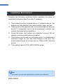
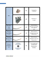
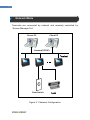
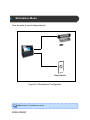
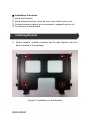
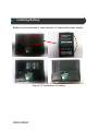
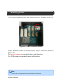
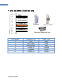
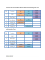
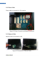
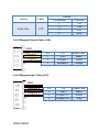
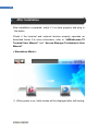
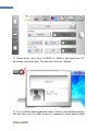
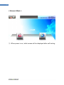
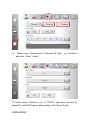
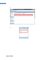
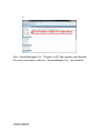
2 © Copyright 2012, NITGEN&COMPANY Co., Ltd. All rights reserved. ` Unauthorized reproduction of part or all of this manual’s content in any form is prohibhited. Product specification may change whithout prior notice to improve functionality. NITGEN&COMPANY and NITGEN logos are registered trademarks of NITGEN & COMPANY. Other names and trademarks belong to resprective companies. NITGEN & COMAPY Customer Service Center Tel: +82.2.513.2147 Fax: +82.2.513.2191 Email: [email protected] 3 Contents CHAPTER1 BEFORE INSTALLATION ........................................................ 4 INSTALLATION ENVIRONMENT ...............................................................................5 PRODUCT PACKAGE ............................................................................................6 PRODUCT DETAIL ................................................................................................8 CHAPTER2 SYSTEM CONFIGURATION .................................................. 12 NETWORK MODE...............................................................................................13 STANDALONE MODE ..........................................................................................14 CHAPTER 3 INSTALLATION ..................................................................... 15 INSTALLING BRACKET ........................................................................................16 CONNECTING EXTERNAL DEVICES ......................................................................17 INSTALLING BATTERY ........................................................................................18 SELECTING POWER ...........................................................................................20 CONNECTING EXTERNAL CABLES .......................................................................21 FIXING TERMINAL ..............................................................................................27 CHAPTER4 AFTER INSTALLATION ......................................................... 28 AFTER INSTALLATION ........................................................................................29 4 Chapter1 Before Installation Installation Environment -5 Product Package -6 Product Detail -8 5 Installation Environment Consider the following conditions before selecting the place of installation, and get consent from user if necessary. ① This product should be installed indoors. If installed outdoors, the product must be protected from direct sunlight, snow, and rain. ② Cables must not be exposed and it is recommended that they are buried. If it impossible due to the environmental condition, get consent from user before installation. ③ Supply the power after cables are connected correctly. Do not change connection while power is supplied. ④ This product can be used more efficiently when it is installed at a convenient height for user and close location of the door. The recommended height for normal users is 150cm (4.9Ft) from the ground. ⑤ This product needs AC100~240V 50/60Hz power. Note If the power is not grounded appropriately, a product may malfunction. 6 Product Package Item Terminal Wall Bracket Adaptor Shape Quality Usage 1EA Access Controller 1EA A support projecting From wall 1EA Power supply to terminal Power Cable 1EA 7 2EA Terminal fix to bracket Bolt 4EA 2EA (6 Pin) Door/Aux connector and external wire Wiegand Input Cable to wall Cable between Door/Aux Cable Bracket fix Cable between 1EA Wiegand input and (5 Pin) external wire Wiegand Cable between Output Cable 1EA (5 Pin) external wire “AccessManager Software Installation CD Wiegand output and 1EA Professional” Management Software 8 Product Detail ① Touch Screen LCD ② Camera ③ Status LED Blue: Stand-by Green: Success Red: Fail ④ Fingerprint Scanner ⑤ RF Card Scanner < Front Panel > ① Touch Screen LCD: It provides user interface. User can check the status of terminal and select various configurations. It includes touch panel interface, user can easily select by tapping. ② Camera: It snapshots user when authentication is processed. ③ Status LED: It indicates the result of authentication. Blue means “stand-by”, green is “successful result” and red is “failed result”. ④ Fingerprint Scanner: It captures fingerprint image when user registers or authenticates. 9 ⑤ RF Card Scanner: It reads RF card when user registers or authenticates card. ① ② Reset Button USB Port ③ Speaker < Bottom View> ① Reset Button: It rebstarts terminal without disconnecting power. ② USB Port: It supports USB memory stick to download logs/users and upload users/firmware. ③ Speaker: It outputs sound when sound option is enabled. 10 ② Wiegand In ① Door/Aux Jumper ③ Battery Area ④ Tamper Switch ⑤ Power Con. ⑥ Wiegand Out ⑦ Network ⑧ AUX Con. ⑨ Door Con. < Rear View > ① Door/Aux Jumper: It selects whether terminal supplies power to Door/Aux connector. Refer to “3.4.1 Cable Connection for Lock”. ② WIEGAND Input Connector: It receives external device’s external wiegand signals. ③ Battery Area: Optional battery can be inserted in this area. When power failure is occurred, battery supplies alternative power. (Battery is sold separately.) 11 ④ Tamper Switch: It warns when terminal is torn off from wall bracket. ⑤ Power Connector: 12V power adaptor cable is connected in this connector. ⑥ Wiegand Output Connector: It outputs wiegand signals for external device when authentication is succeeded. ⑦ Network Connector: It uses RJ45 connector for normal Ethernet or POE connection. ⑧ Aux Connector: It is used for auxiliary door control signals. ⑨ Door Connector: It is used for door control signals. Chaper 2 System Configuration Network Mode - 13 Standalone Mode - 14 13 Network Mode Terminals are connected by network and remotely controlled by “Access Manager Pro”. Server PC Client PC Network(TCP/IP) Terminal Door Switch Lock Figure 2.1 Network Configuration Standalone Mode One terminal is used independently. Lock Door Switch Figure2.2 Standalone Configration eNBioAccess-T5 controls two doors. 15 Chapter 3 Installation Installing Bracket - 16 Connecting External Devices - 17 Installing Battery - 18 Selecting Power - 20 Connecting External Cables - 21 Fixing Terminal - 27 ※ Installation Procedure ① Install wall bracket ② Install external devices (such as lock, door switch and so on) ③ Connect external cables (such as network, wiegand and so on) ④ Fix terminal to wall bracket Installing Bracket ① Select suitable installion location and fix wall bracket with four bolts included in the package. Figure3.1 Installation of wall bracket 17 Connecting External Devices The following devices are supported, please refer to the table. ① Locking Device ② Door Switch ■ Lock Types and Specifications Type DeadBolt Specification Remarks Voltage: DC12V, Supply power Current: less than1A NC / NO Type Electronic Voltage: DC12V, Supply power Magnetic-Lock Current: Less than 1A NC / NO Type Electric Strike Voltage: DC12V, Supply power Current: Less than 1A NC / NO Type *Max. Switching Voltage: Automation Door 220V DC/ 250V AC. *Max. Switching Current: Contact signal only Less than 2A DC/ AC ☞NC(Normal Close): Unlocked, Opened upon emergency ☞NO(Normal Open): Locked, Closed upon emergency Installing Battery Battery can be inserted in rear case for un-interrupted power supply. Figure 3.2 Installation of battery 19 Caution for battery Please follow instruction below in order to avoid heating, fire, explosion and so on. - Contact manufacturer immediately when battery has notiable expansion. It may cause serious danger. We do not take any responsibility for unrecommended charging or discharging of bettery. Keey away from inflammable material. Do not leave in ther car in hot weather. Do not use in a hot and humid enviroment. Do not use long time on duvet, electric blanket or carpet. Do not store for a long period of time in a confined space with power-on. Keey battery’s terminal contact away from metal product such as netlaces, coins, keys, and watches. Do not disassemble, compress or penetrate. Do not give a strong impact. Do not expose to above 60℃ temperature. Keep away from moisture. Selecting Power The terminal operates with two power soruces – adaptor and POE. Figure3.3 Power Selection Switch Power selection switch is located above power connector shown in Figure 3.3. For power adaptor, move switch tap to right direction. For POE power, move switch tap to left direction. Note POE mode is only possible in terminal with POE module. 21 Connecting External Cables The following cables can be connected to terminal. 1. Door Control Cable 2. Network Cable 3. Power Cable 4. Wiegand Input Cable 5. Wiegand Output Cable Some cables may not be connected according to application. 3.4.1. Door Control Cable (J17 and J18) Housing Receptacle Cable YMW025-06R YMT250 UL1007, 24AWG ☞ Caution ① Make sure cable connection is correct before supplying power. Wrong connection causes permernent damage to terminal. ② When connecting to automation door, use contact signal by disconnecting JP5 in using J17 or JP6 in using J18. When delivered, [JP5] and [JP6] are connected by jumper. ③ Some locks do not have door monitoring signal. Figure 3.4 Power-Supplying Jumper for Lock JP5 and JP6 are located in the back of the terminal above Door/Aux connector. Note [JP5] and [JP6] are jumpers for power supplying(12V) to a doorlock. If you use external power, those jumpers must be disconnected before connecting power. 23 ■ 잠금 장치 종류별 케이블 결선 방법 GND Door Open Door Monitor Contact_B Deadblot Electric Strike Common Contact_A Electronic Magnetic Lock PIN Number Connector J16 Cable Color 1 GND Black 2 Door Open White 3 Door Monitor Blue 4 Contact_B Orange 5 Common Yellow 6 Contact_A Green ■ Connection for Deadbolt/ Electic Strike/ Electric Magnetic Lock PIN Function 1 GND 2 Door Open 3 Door Monitor 4 Contact_B 5 Common 6 Contact_A NC NO DOOR OPEN GND GND OPEN COM(DoorStatus) COM(DoorStatus) Switch OPEN Switch NC NO (DoorMonitoring) (DoorMonitoring) VCC(+12V) VCC(+12V) ■ Automation Door PIN Function NC NO 1 GND 2 Door Open 3 Door Monitor 4 Contact_B 5 Common Conatct Contact 6 Contact_A Contact Contact DOOR OPEN OPEN Switch OPEN Switch 25 3.4.2 Power Cable Power cable is connected to J14 connector J14 U26 4 Figure 3.5 Power Connector and Network Connector 3.4.3 Network Cable Network cable is connected to U26. Figure 3.6 Connection of Netowrk Cable Hosing Cabling Cable RJ45, 8Pin UTP Pin Number Function 1 TXP 2 TXN 3 RXP 6 RXN 3.4.4 Wiegand Output Cable (J16) GND Wiegand 1 Wiegand 0 Pin J16 Cable Color 1 GND Black 2 Wiegand 1 Yellow 3 Wiegand 0 Orange 3.4.5 Wiegand Input Cable (J15) GND Wiegand In 1 Pin J16 Cable Color Wiegand In 0 1 GND Black 2 Wiegand In 1 Brown 3 Wiegand In 0 Gray 27 Fixing Terminal ① After cables are connected correctly, place the terminal on the bracket using 4 locking holes. Figure 3.7 Placing the terminal on bracket ② Fasten terminal with bracket using bolts as shown in Figure 3.8 Figure 3.8 Fastening the terminal with bracket Chapter 4 After Installation After Installation - 29 29 After Installation After installation completed, check if it is done properly and plug in the power. Check if the terminal and external devices properly operates as described below. For more information, refer to “eNBioAccess-T5 Terminal User Manual” and “Access Manager Professional User Manual”. < Standalone Mode > ① When power is on, initial screen will be displayed after self-testing. ② Select menu “Network Icon Normal Type” and set “Disable” and click “Save" ③ In initial screen, network status icon is changed to ‘SO’ – standalone mode. 31 ④ Select menu “User Icon USER + Button” and input user’ ID, priviledge, and auth-type. The first user must be “Master”. ⑤ Try to authenticate registered users. If door is connected properly, left top door icon of initial screen is changed to open-status when authentication is succeeded. (Door is configured to open door when succeeded.) In standalone mode, the first registrated user has master-priviledge. 33 < Network Mode > ① When power is on, initial screen will be displayed after self-testing. ② Select menu “Network Icon Normal Type” , set “Wireline”, and click “Save” button ③ Select menu “Network Icon TCP/IP” and input terminal ID, server IP, and DHCP mode. After setting, click “Save” button. 35 ⒜ ⒝ ⒞ Run “AccessManager Pro.” Program in PC and register new terminal. For more information, refere to “AccessManger Pro.” user manual.