1
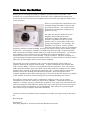
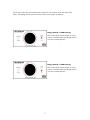
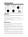
Tone King “Ironman”
User’s Manual
1.0
7/23/2013
Tone King Amplifiers
A division of Premier Builders Guild LLC
4401 Eastern Avenue, Bldg 46-3G, Box 38
Baltimore, Maryland 21224
www.toneking.com
[email protected]
Note from the Builder
Thank you for choosing Tone King’s “Ironman” precision power attenuator. The
Ironman is a new generation of power attenuator, with a sophisticated design that
preserves the tone and feel of your amplifier quite well while reducing the volume level
at the speakers.
There are two important components to the
Ironman design that make it unique and
particularly effective - the tuned reactive
load and the transformer coupled power
division circuitry.
The idea was that the load seen by the
amplifier should always have the
appropriate complex impedance curve
so that it responds as it does to a real
speaker load. A real speaker load varies
greatly with frequency. For example, the
impedance of a typical "8 ohm" speaker
may rise to 60 ohms or more at its resonant
frequency (usually around 60-80Hz), and then rise again to many tens of ohms at high
frequencies. An amplifier responds a lot differently when driving a complex load like
this, compared to a simple resistive load (as is used in most attenuators). I developed
the Ironman's reactive load circuit by matching the results of impedance curve
measurements I ran on an actual speaker in typical cabinet, and then tweaking the
resulting design thought empirical methods in order to create a load circuit that is most
effective at preserving the tone and feel of your amplifier.
The second part of the equation is the circuitry that divides the power from your
amplifier between the speaker and the load. In other attenuators, this is often done
with a resistor ladder. There are two problems with this approach - first, the resistor
ladder itself can become part of the load, which means that the amplifier sees a simple
resistive load. Second, in dividing the power this way, a voltage divider is effectively
formed between the dividing network and the speaker. Since the speaker has a
complex impedance that varies with frequency, the result is that the frequency response
at the speaker is altered, usually dulling the top end and muddying the sound.
The scheme I chose involves 100% transformer coupling, using a set of custom
transformers, so that the connection between the amplifier -> load and between the
amplifier -> speaker is purely transformer coupled at every step of the attenuation dial.
This is an expensive and elaborate design (each step of the dial requires its own tap on
one of the custom transformers), but is significantly more effective at preserving the
tone and feel of your amplifier than other methods.
I thank you for your purchase of the Ironman, and I hope you enjoy using as much as I
do.
Best Regards,
Mark Bartel
Tone King Amplifiers, a division of Premier Builders Guild LLC
1
Safety Instructions (Important !)
1. Please read these instructions, and keep them for reference.
2. Please follow all instructions described here.
3. Do not use this apparatus near water.
4. Clean only with a dry cloth.
5. Do not block any ventilation openings.
6. Do not operate near any heat sources such as radiators or heat registers.
7. Only use attachments/accessories specified by the manufacturer.
8. Refer all servicing to qualified service personnel. Servicing is required when the
apparatus has been damaged in any way. For example, if the power supply cord or
plug is damaged, liquid has been spilled or objects have fallen into the apparatus, the
apparatus has been exposed to rain or moisture, does not operate normally, or has
been dropped.
2
Contents
1. Front Panel Controls
4
Attenuate / Bypass Switch
4
Attenuation Knob & Range Switch
4
2. Back Panel Controls
6
Amplifier Input
6
Speaker Connections
6
Line Out
7
3. Using the Ironman
8
Purpose
8
Impedance Matching
8
Adjusting the Controls
8
Use as a Dummy Load
8
What to Expect When Attenuating
9
4. Warranty
10
3
1. Front Panel Controls
Attenuate / Bypass Switch
This switch allows you to completely bypass the attenuator. In Attenuate mode, the
attenuator is active, and in Bypass mode, the attenuator is disabled. In Bypass mode,
the speaker outputs are connected directly to the amplifier input, and the attenuator
circuitry is completely disconnected from the signal path. Because of this, the
impedance matching switches (on the back panel) have no effect in Bypass mode.
Important - do not toggle the Attenuate/Bypass switch while playing through your
amplifier. Dampen the strings of the guitar while toggling this switch.
Attenuation Knob & Range Switch
The Attenuation knob determines the amount of power sent to the speaker. At 0db, the
signal is not attenuated, and all of the power from the amplifier is sent to the speaker.
The maximum possible attenuation is -40db. At this setting, nearly all the power from
the amplifier is dissipated in the Ironman, and very little is sent to the speaker. At this
setting, you can safely unplug the speaker, and use the Ironman as a dummy load.
Important - do not adjust the Range or Attenuation controls while playing
through your amplifier. Dampen the strings of the guitar while adjusting these
controls.
4
You'll notice that the Attenuation dial is split into two ranges at the left side of the
knob. The Range switch selects between these two ranges, as follows:
Range Switch: 0-30db setting
The attenuation values shown at left in
red are available when the Range switch
is in the 0-30db position.
Range Switch: 0-40db setting
The attenuation values shown at left in
red are available when the Range switch
is in the 0-40db position.
5
2. Back Panel Controls
Amplifier Input
The amplifier should be connected to the Ironman's Amplifier input (1) with a standard
1/4" speaker cable. The Amplifier Impedance switch (2) should be set to match the
impedance of the amplifier.
Here are some simple rules for connecting the amplifier to the Ironman:
1. If your amplifier has an impedance switch, select the highest available impedance in
the range of (4 ohms through 16 ohms).
2. Set the Ironman's Amplifier Impedance switch to match the impedance selected on
your amplifier.
Speaker Connections
Two speaker jacks are provided for connecting speakers to the Ironman (3). Both
speaker jacks are wired in parallel. If you are only connecting one speaker to the
Ironman, you can use either jack.
The Speaker Impedance switch (4) should be set to match the total combined
impedance of the speaker(s) connected to the Ironman. If you are connecting a single
speaker to the Ironman, simply set the Speaker Impedance switch to match that
speaker's impedance.
If you are connecting two speakers to the Ironman, it is best to use two speakers with
the same impedance. If you do this, then the total combined impedance will be 1/2 of
each speaker's impedance. Here are a few examples of how to set the Ironman when
using two speakers:
- If you are connecting TWO 8-ohm speakers to the Ironman, using the two Speaker
jacks provided (3), then you should set the Speaker Impedance switch (4) to 4 Ohms.
- If you are connecting TWO 16-ohm speakers to the Ironman, using the two Speaker
jacks provided (3), then you should set the Speaker Impedance switch (4) to 8 Ohms.
6
Line Out
The Ironman's Line-Out jack (5) provides a line-level signal that can be used to drive
another amplifier, mixing board, computer sound input, or any other line level input.
The specs for this output signal are as follows:
•
•
•
Output Level:
Impedance:
Interface:
approx. 0 - 1V p/p (adjustable)
10K Ohms
Unbalanced, mono 1/4" connection
The adjustable level control (6) allows you to control the level of the line-out signal.
This is useful if the Line-Out is being used to drive another guitar amplifier, where you
need to reduce the level to avoid overdriving the guitar amplifier.
The line-out signal is generated from the amplifier input, and does not change as you
vary the attenuation knob. The line-out signal will be present even when the amplifier
is bypassed.
The line-out signal has a bit of basic EQ to make it more closely represent the sound
from the speaker, but this circuitry does not include a sophisticated speaker
simulation.
7
3. Using the Ironman
Purpose
The Ironman precision attenuator allows you to reduce the volume level at the
speaker(s) while allowing the amplifier to operate at full output power, for natural power
tube overdrive and distortion. The Ironman allows you to select the amount of the
amplifier's output power that is sent to the speakers, with the rest of the power being
dissipated within the Ironman.
Impedance
Impedance Matching
One unique feature of the Ironman is its dual Impedance controls - one for the
amplifier input, and one for the speaker output. These dual impedance controls allow
you to match your speaker to your amplifier, even if the speaker impedance differs from
the amplifiers' output impedance.
You can even perform this matching without attenuating. To do this, simply set the
attenuation knob to 0db, and make sure the Attenuate/Bypass switch is in the
Attenuate setting. Then, set the Amplifier Impedance switch and the Speaker
Impedance switch as appropriate to match the speaker to the amplifier.
Adjusting the Controls
When adjusting any of the front or back panel controls, it's best to dampen the strings
of your guitar, so that no significant amount of signal is being generated by the
amplifier.
Use as a Dummy Load
The Ironman may be used as a dummy load, to provide a proper load for your amplifer,
with no speakers attached. This is typically done in recording, where the Ironman's
Line-Out will be used to drive a mixing board, or when an amplifier is being "slaved" to
a larger amp (with the Line-Out signal driving another amplifier).
Here's how to set the Ironman when using it as a dummy load:
•
•
•
Attenuation Control:
Range Switch:
Attenuate/Bypass Switch:
-40db
0-40db
Attenuate
•
•
•
Amplifier Impedance Switch:
set to match amplifier output impedance
Speaker Impedance Switch:
setting doesn't matter
Nothing plugged into the Speaker jacks
8
What to Expect When Attenuating
Although the Ironman attenuator does an excellent job of reducing output power
without changing the tone of the amp’s circuitry, there are other variables in play at
lower volume which do result in some apparent tone change. Here are a few factors
that you should be aware of Speaker breakup and compression is a big part of the tone and feel of the amp when
played at high volume. At low power settings, the speaker responds differently, and
does not break up and compress as it does at high power.
The ear’s natural response curve varies at different volume levels, which changes the
way you perceive sounds at different volume levels. Quieter sounds tend to give the
impression of having less bass content.
At lower volume, there is a tendency to hit the guitar strings harder and play more
aggressively than you would if the amp were tuned up very loud. It may take some time
to get used to maintaining your playing style at reduced volume.
9
Premier Builders Guild LLC
Limited Warranty
Premier Builders Guild LLC
201 S. Highland Avenue, Suite 204
Pittsburgh, PA 15206
This warranty gives you specific legal rights; you may also have other rights which vary from state to state. There are
no express warranties except those listed below.
Length of Warranty
This warranty shall remain in effect for five years from the date of sale of the product as shown on the original bill of
sale.
What is Covered
This warranty covers all defects in material and workmanship in this product, with the following exceptions:
1. Damage or deterioration of the cabinet, or any other cosmetic damage which occurs after delivery is not
covered by this warranty.
2. Damage after initial delivery resulting from accident, unreasonable use, or neglect, is not covered by this
warranty.
3. Damage resulting from the performance of repairs by someone other than the Tone King Amplifier
Company is not covered by this warranty.
4. Damage occurring during shipment or delivery of this product to the Tone King Amplifier Company
after initial delivery of the product is not covered by this warranty.
5. Vacuum tubes are considered a user-replaceable item, as they are expected to wear out and require
replacement over a reasonable period of time. Tubes are warranted to be serviceable for a period of 90
days from the date of sale.
6. The speaker(s) in this amplifier has(have) been selected for use only with this amplifier. If the
speaker(s) of this amplifier is(are) connected to an amplifier other than the intended amplifier, any
warranty of this speaker shall be deemed void.
What We Will Pay For
The Tone King Amplifier Company will pay for all labor and material expenses to fix or replace all items covered
under this warranty. The customer will pay shipping charges to return the product to the Tone King Amplifier
Company. If the necessary repairs are covered under this warranty, the Tone King Amplifier Company will pay any
shipping charges required to return the product to the customer.
Limitation of Implied Warranties
All express or implied warranties of merchantability and fitness for a particular purpose are limited in duration to the
length of this warranty, unless otherwise provided by state law.
Exclusion of Certain Damages
The Tone King Amplifier Company’s liability is limited to the repair or replacement, at our option, of any defective
product, and shall in no event include incidental or consequential damages of any kind. Some states do not allow
limitations on the length of an implied warranty and/or do not allow the exclusion of incidental or consequential
damages, so the above limitations and exclusions may not apply to you.
Obtaining Warranty Service
If your unit requires service, it should be returned to the Tone King Amplifier Company at the address listed above.
Before returning the unit, you must contact the Tone King Amplifier Company and obtain return authorization.
10