1
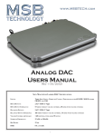
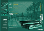
Select DAC II
Users Manual
Rev 2 (8/2015)
1
Select Users Manual
The Heart of the System - a Preamp and DAC
This product is a unique combination of a very high performance DAC and the ultimate
passive preamp. It is intended to be used as both for the best possible sound in your system.
Our preamp philosophy is based on the belief that from the moment analog audio is created,
every transition that is made degrades the quality. That means that an active preamp with
many stages if perfect would have no effect and any imperfection would result in degradation
of the music. That is why we offer a passive preamp within the SELECT, to achieve the
simplest, shortest possible signal path, with the least possible degradation of the true music.
Volume Control and Analog Input
The SELECT input structure is flexible with the option for one or more analog inputs, and many
digital inputs. It is designed to be the last component in your system before the amplifiers.
With its incredibly low impedance output, especially for a passive preamp, it can drive long
interconnects and handle any type of amplifier input stage design with optimum performance.
Unless you have many analog sources in your system, you should be able to eliminate your
current preamp. The analog input can be turned on in the menu and can be set to volume
control the analog input or bypass the analog input. In this way you can use another volume
control for your analog sources if you like. Otherwise set your preamp to a volume that
matches the SELECT output and use nothing but the SELECT volume control in your system.
CD, DVD-A
Transport
Phono
Preamp
Analog
R/L
Digital
SELECT
Analog
R/L
AMPs
Setup and Quick Start
The interface is quite simple with few user controls. Input source select defaults to auto. The display will let you
know if you have an active input. On power up, the volume is reset to the programmed startup level. Default is 70.
Turn the volume knob up until you hear music.
Power - The SELECT comes with a high performance outboard power supply. The supply automatically detects and
switches between 240V and 120V. This is not a switching supply that works at any voltage, but a linear supply with
automatic switching of the transformer leads. The power supply is switched on and off with a button on the front. It
can also be remotely controlled. The LED in the front of the Power Base indicates Red if plugged in and turned off
and White if ON. Always allow three to five hours for the SELECT to warm up and reach thermal equilibrium before
critical listening.
Inputs - The SELECT comes with the digital input modules you ordered. Connect any digital input to any active digital
audio source. The frequency and bit depth of the incoming signal will be read out on the front panel and analog audio
will be found on the analog outputs.
Outputs - A range of Output Modules are available. Connect the balanced or single-ended analog outputs to any
amplifier and audio should be present. The output level is controlled with the knob or remote.
Burn-In
The concept of burn-in is little understood. Does it take your ears some time to get used to the incredibly detailed and life-like sound of
an MSB product or is something actually changing? The feedback we receive leads us to recommend at least 100 hours of burn-in on
this DAC. Customers generally report improvement up to one month.
Warning: Please verify that the SELECT you just purchased is covered under warranty. This DAC was sold to the Distributor named
on your box label and in the “about” section of your setup screen. The country and date of manufacture is also specified. If the
country and year do not match your purchase location, your warranty may be invalid. Check with MSB.
Hybrid DAC Specifications
Output Impedance: Balanced Output: Single Ended Output:
Volume Control:
Max Sampling Frequency: Bit Depth: Dynamic Range:
75 ohms
3.5 V RMS (10 Vpp)
2.8 V RMS (7.8 Vpp)
1 dB stepped attenuator
768 kHz or Quad Rate DSD native
32 bit
173 dB (28.5 Effective Bits)
2
The Universal Media Transport Signature
V is a great companion to the SELECT.
It is shown here with the Dual Signature
Transport Power Base. The Data CD V
is also a great option, shown here in Matt
White.
To complete your system, MSB offers two Amplifier models. Here the M203 is shown, available in Matte White
or Matte Black.
3
Unique Technology - the past and the future
In the 1980’s early DACs were all 16 bit ladder DACs, with a precision laser-trimmed resistor creating the appropriate analog level for
each of the bits. The DACs worked well and sounded good. They were quite expensive as very accurate resistors were required. Then
along came the “single bit” DACs. Rather than using a resistor to create an analog level, pulse width modulation was used. Basically
each bit was created by turning a switch on and off for the appropriate length of time. The resulting square wave pattern was filtered
to create a smooth output. The expensive resistors were gone, and so was the good performance. Next came the Delta Sigma DAC. It
used the same pulse width modulation but rather than creating a single large pulse for each data point, the data point was created with
many small pulses. This allows the pulses to be smoothed with a
less radical filter, and that approach became the basis of essentially
all the DACs on the market for the next 20 years.
But MSB instead drew from the older, superior ladder technology,
and continued to make incredible improvements over the years.
Discrete high precision Ladder DACs were built, and later replaced
by Sign Magnitude Ladder DACs. Precision has been increased as
well as output power.
Today the HYBRID DAC used in the SELECT allows the DAC
to drive the output directly with no opamp or output stage by
implementing 16 parallel DAC channels! This is a first in the
industry.
Original Platinum DAC module
The SELECT contains
8 two channel HYBRID
DAC modules, a total of 16
channels.
Organization of the Users Manual
The SELECT has many special features and can be broken down into 5 basic parts. Each has a section as well as the operation manual.
They follow the signal flow:
Inputs --> Clock --> Digital processing and DACs --> Outputs --> Power Supplies
Inputs
page 6
Clocks
page 9
DACs
page 10
Outputs
page 10
Power Supply
page 11
Operation page 15
Upgrades
page 18
4
THE DAC STORY
How DACs work
Delta Sigma DACs (Single Bit)
Each sample or jug is
filled to the right level
with many measuring
cups, poured to reach
the target level.
010010100011101000110110
A DAC is a circuit that converts
digital measures of audio amplitude
in discrete steps into a continuous analog
electrical equivalent of the sound to be reproduced. The
amplitude is a digital number (like a 16 bit word) and the
steps occur based on the sampling rate (like 48,000 times per
second). This process is very much like an endless conveyer
belt with empty one gallon jugs on it, moving by a filling
station. The size of the jug is fixed, the rate they pass by is
determined by the sampling rate. The goal of the DAC is to
fill each jug to exactly the right level specified by the music.
There are three techniques used to accomplish this; Delta
Sigma, Ladder, and the MSB Sign Magnitude Ladder.
A ladder DAC is different
in that instead of a single
measuring cup (or bit), a
whole array of cups are
available, from very
small to very large.
Ladder DAC
Any combination of cups
can be used to fill each jug
to exactly the right level.
Line speed
is like Sampling
Rate (48,000 per
By keeping a running tally of the error and by going a little over
and a little under in many many samples, a very accurate average is
reached, but only with an aggressive filter applied to the output.
No
filtering is
required but
the accuracy
is defined by
the cumulative
error of all
What about Jitter?
Jitter is a variation in the speed of the conveyer belt.
With a Delta Sigma DAC, the quantity of water ending
up in the jug is dramatically affected by the speed
change because the whole cycle is occupied with
the application of many small scoops of water. With
either Ladder DAC method, all the water is placed in
the jug at the same time, and even if the jug is a little
ahead or behind in the conveyer belt, the quantity
is still accurate. That is why we never heard much
about jitter until the first Delta Sigma DACs arrived
on the scene.
A “one bit” measuring cup is either
full or empty. With 64 times oversampling, the cup is only 1/64th
the volume of the jug. This rather
crude cup does not
come close to
being accurate
enough. The cup
would need to be
1/16,777,216th
the volume of the jug
to be accurate.
MSB Sign Magnitude Ladder DAC
The MSB Sign Magnitude
Ladder DAC is like a Ladder
DAC but refined in two ways.
Because the jars are
typically 1/2 full when
finished, we start
with very accurately
1/2 filled containers
instead of empty ones.
From there, we again
use the wide range of
measuring cups to either add
or take away from each jar.
Again each jar is filled exactly so no
filtering is needed, but because we only had to add or subtract a little bit
our accuracy is higher. Because our hearing is most sensitive to low level
sound (sound near the 1/2 full zero crossing) our DAC is most accurate
near 1/2 full where we use the smallest and most accurate measuring cups.
What about Upsampling?
The MSB HYBRID DAC
No commercial DAC is available with the level of accuracy
produced using our own discrete logic and resistors in the
Hybrid DAC module. MSB is unique in this respect. The result
is a 173 db dynamic range well exceeding the theoretical limit
of a 24 bit source.
Synchronous Upsampling like MSB does just means adding more jars
between the existing jars and moving them faster down the line. By
looking at many jars before and after the new empty one, we calculate
how full to make it. The result is smaller steps as shown in the waveform.
This reduces the load on digital filter. In a low resolution system it
improves the sound, but in an accurate high-res system it is best not
to upsample.
5
Input Modules
About the 4 INPUT Module Slots
The SELECT has four input module slots. They are labeled A through D. There are two classes of input modules, Analog and Digital.
Analog modules must be placed adjacent to the Analog Output module. They can be either input or output modules. Digital modules
are only inputs and can be placed in any position.
Each module is completely self contained. It is recognized by the SELECT and identified on the display. When not selected the module
is turned off.
Analog Input Module (XLR or RCA)
The Analog Input module provides a second analog input. It is set up in the menu and can either be used with volume control or can
bypass the volume control. It must be placed adjacent to the Analog Output module. When installed and activated in the menu, 2nd
ANALOG INPUT will show up in the menu. It can either be Balanced or Single Ended.
Subwoofer Output Module (XLR or RCA)
The Subwoofer output module provides an isolated output suitable for connection to a powered subwoofer or class D amplifier.
Subwoofers need a lot of power and they are not sensitive to high frequency noise. So the speaker manufacturers like to match their
subwoofers up with some pretty low quality amplifiers, with switching power supplies and not much filtering. So what’s the problem? The
subwoofers sound perfectly OK. The problem we found is that you have to hook that subwoofer up to your ultra clean, ultra precision,
perfect analog output from your DAC. The presence of this noisy subwoofer amplifier just being hooked up to your DAC creates
incredibly obvious noise in the DAC and thus distortion on your main amplifier and speakers. Its like serving fine wine in paper cups.
Its just intolerable. The concept of this output is that class D amplifiers found in subwoofers create a lot of electrical noise that can be
carried BACK to the DAC and can interfere with the DAC conversion and clocks. We aggressively block that noise with the Subwoofer
output module.
It must be installed adjacent to the Output Module or another Analog Module.
Digital Input Modules
There are a number of digital input modules shown below. Some have one input and others have more than one. New modules will be
added from time-to-time. In the case where a module contains more than one input, the DAC will recognize that and simply add another
input to the input list allowing you to select each input as if it was a separate module.
Digital Input Module - Optical and Coax with Word Sync Clock Output
This digital module is like two inputs in one. Both are industry standard S/PDIF inputs capable of accepting data streams up to 24 bits
and 384 kHz as well as DSD via DoP up to double rate. Note that some sources may not be able to output this high a rate on these format
connectors but at least the input can handle it.
It is very valuable to keep the source in sync
with the DAC so we provide a Word clock
output using a BNC connector that would
allow you to sync with the source. This sync
is primarily a feature for studio use, where
the ultra low jitter DAC clock can be used as
the master studio clock. This issue of clock
sync is not easy to understand. The quality
of the data being received is not changed by
syncing the source, but the noise associated
with recovering the data from a “different”
clock is substantially less.
6
Digital Input Module - Balanced XLR with Word Sync Clock Output
This digital module is a single input. It is the industry standard S/PDIF input capable
of accepting data streams up to 24 bits and 384 kHz as well as DSD via DoP up to
double rate. Note that some sources may not be able to output this high a rate on
this format connector but at least the input can handle it. It is very valuable to keep
the source in sync with the DAC so we provide a Word clock output using a BNC
connector that would allow you to sync with the source. This sync is primarily a
feature for studio use, where the ultra low jitter DAC clock can be used as the master
studio clock. This issue of clock sync is not easy to understand. The quality of the
data being received is not changed by syncing the source, but the noise associated
with recovering the data from a “different” clock is substantially less.
The MSB PRO I2S Network
One of the most powerful features of MSB products is the PRO I2S network. Most MSB
products have a PRO I2S connection available. The MSB PRO I2S has the following
capability:
•
•
•
Digital Input Module - Dual PRO I2S
This digital module is like two modules in one.
Both are MSB proprietary inputs capable of
accepting data streams up to 32 bits and 384 kHz
as well as DSD up to quad rate. Note that some
MSB sources may have a limited output rate.
Part of the PRO I2S interface includes a master
clock link so no additional clock sync connection
is needed. This issue of clock sync is not easy to
understand. The quality of the data being received
is not changed by syncing the source, but the
noise associated with recovering the data from a
“different” clock is substantially less.
•
Works with standard CAT6 cable
Simultaneous transmission of 8 audio channels with 32 bit resolution at 384 kHz
sampling rate.
MSB CAN Interbox communication Bus (for communications between
boxes)
Low Jitter master clock distribution from the DAC back to the Transport.
This network is our answer to 384 kHz audio transmission and multichannel transmission
in the same package. We provide PRO
I2S outputs on our own transports. With
multichannel sources, up to 8 channels of
decoded data can be sent through one
wire to separate DACs. CAT6 wire is
very convenient as it has become the
standard for all computer networks.
Several cables are available for
connecting MSB transports to the
SELECT Line including CAT6 cable
at any length up to 80 feet.
NOTE: Do not use CAT7 or any
shielded network cable. This is
NOT a computer network and it
will not work.
7
Digital Input Module - Quad Rate USB
This digital module contains an impressive USB
interface. It is ground isolated and the DAC will keep
the computer in sync for the lowest possible noise.
This interface can support 24 bit, 384 kHz inputs
and DSD Native or DoP up to quad rate. Computer
compatibility changes with every new operating
system update so beware. As of this writing, the Mac
OS does not support quad rate native streaming. That
may change at any moment.
WARNING! Because this USB input is ground
isolated, use with an audiophile isolated ground
cable, isolated cable, battery powered cable, Y
cable, or a cable with a switch will result in a
floating input and likely result in a complete failure
of the input module. Always make sure the USB
cable has the ground and power connected!
Apple MAC OS
On the MAC the USB is plug and play. The MAC will
recognize the USB DAC and its capabilities and will
allow the output to be set to any sample rate desired.
The bad news is, with certain programs such as iTunes,
the output sample rate has to be set manually when
the file sample rate changes. So if you set the output
for 192 kHz, and played a 192 kHz file, it would play
perfectly, but if you then played a 44.1 kHz CD, the
MAC OS would upsample that file to 192 kHz. It is
better to change the output to 44.1 kHz and play the
file bit-perfect. Fortunately there is an APP called BIT
PERFECT. Download it and the MAC with the MSB
Quad USB will play perfectly.
Notice that the presence of the MSB USB has allowed
352.8 and 384 kHz sample rates to show up on the
menu. Normally they are not present. iTunes will
play at whatever sample rate you select in this setup.
For the latest news about USB issues check the
SUPPORT tab of the MSB web site.
Windows OS
The amazing thing about the MSB USB input with
Windows is that once you get it set up it works
perfectly, with every file playing bit-perfect at its
native sample rate up to 384 kHz and quad rate DSD
with no user intervention. Just pick the song and play. The rest is automatic and works perfectly. The bad is that MSB drivers will have
to be installed, and your music must be played with a properly set up player program like Foobar or JRiver. It’s a small price to pay for
great playback, and MSB will help walk you through the process.
You can find the latest USB Drivers and setup instructions on our website on the support page.
8
Digital Input Module - Renderer
This digital module contains an impressive audio
renderer. This input is connected to a computer
network and allows the DAC to become an endpoint
for a range of music players and servers. A separate
manual is included for this input. When installed
the IP address of the Renderer can be found in the
ABOUT section of the display menu.
Clocks
One of the most important parts of a DAC is the clock. Clock
jitter is responsible for the digital harshness most often found
in digital products. The MSB clocks are the lowest jitter in
the world. To maintain that low jitter they must be physically
located extremely close to the DAC modules themselves.
This is why outboard clocks cannot compete with a low-jitter
internal clock.
The SELECT ships with a Femtosecond Galaxy Clock
standard, providing 77 femtosecond jitter performance. There
is also an upgrade available to our Femto 33 Clock, the lowest
jitter clock on earth.
The Femtosecond Galaxy Clock offers the second lowest jitter in the
The Femtosecond Clocks plugs into the clock upgrade header world and is standard in the Select II.
on any DAC IV, DAC V or SELECT DAC with an immediate
sonic benefit. An excellent DAC clock tends to reveal the true
nature of the original music. The Select with a Femtosecond
Clock reveals fine, delicate, very dense harmonics that are
accurately organized and therefore correctly reveal the true
sound of the instruments and voices. The lower the jitter of the
clock the more noticeable the effect which scales directly with
jitter. The harmonic congestion that translates to harshness
and the familiar digital “annoyance factor” is just absent. The
music and instruments sound like they are coming from live
mic feeds on the best recordings.
It is easy to replace the clock. Turn the DAC over on a padded
surface and remove the 4 large corner screws. Lift the lid. The
clock can be removed and replaced with the tools provided
with a clock upgrade. Alternatively you may send the DAC
back to the factory to have the clock installed.
The Femto 33 Clock offers the lowest jitter in the world and is a great
upgrade, with half the jitter of the Galaxy.
9
Digital Processing and DACs
There is not much that you need to know about the heart of the DAC. The digital processing is incredibly advanced and can be fully
upgraded by simply playing an MSB upgrade file. There are 8 two channel Hybrid DAC modules that can also be upgraded when the
time comes.
The SELECT uses two of the latest DSPs for ultra fast processing and has an expansion header for future hardware upgrades.
The SELECT has the optimum digital filter installed for each sample rate. They are extremely large FIR filters.
Upsampling
Upsampling has been in and out of vogue for many years. Its benefit has been historically obvious in some DACs and nonexistent in
others. Typically the most processor intensive task in a DAC is the digital filtering. A digital filter takes a look at a window of the music
being played, and because that music was received from a digital source, there are holes in it, between data bytes. The filter looks at the
shape of the signal in the window and tries to figure out what the missing data is. The bigger the window, the better a job it does, and
the bigger processor is needed.
Depending on the sample frequency of the incoming data, a different digital filter is run. Each is a little different and each may not
sound the same. As a result, CDs at 16 bit and 44.1 kHz might sound better or worse than 24 bit 96 kHz files in a particular DAC. But
generally, the higher the sampling frequency, the more processor power can be applied to look at a bigger window and the better job the
digital filter can do. So back in the days of very limited DSP power, upsampling was a great way to get a little more out of the digital
filter. Today with extremely fast DSPs, this limitation is not significant, and it is better to operate directly on the native stream. For that
reason MSB does not support upsampling in the SELECT.
OUTPUTS
There is one output module slot.
There are two versions of the output
modules, a single ended and a
balanced. This design approach
allows an optimized design and
output. If your system changes,
these modules can be swapped out.
The output module contains some of
the most advanced MSB technology.
The outputs are a constant 75 ohm
output impedance regardless of the
setting of the passive volume control
without the addition of a output
buffer, opamp or transistor output
stage. This for the first time allows
you to hear the full resolution of
the DAC.
Output Levels
Balanced Outputs 10 Volts PP
(3.5 V RMS) at a volume of 100.
Impedance is 75 ohms
Single Ended Outputs 7.8 Volts PP
(2.8 V RMS) at a volume of 100.
Impedance is 75 ohms.
External Preamp
Because of this incredible output resolution and amazingly low noise, it is a major compromise to use an external preamp, which adds
many opamps, filters and output drivers, increasing the system noise and adding phase errors. The DAC is the lowest noise part of the
system. All amplifiers are higher noise so the difference between amplifiers should be very obvious with this DAC. Power issues will
also be very obvious and great care should be taken when dealing with bad power.
If for some reason you do want to use an external preamp, set the volume to 94. This is the lowest noise output possible and should give
you the best results without your preamp clipping.
10
Analog Input
The analog input is routed either through the volume control or
bypasses the volume control. This is a menu setup. Part of the
technology included in this DAC may offer some improvement to
any analog source passing through in the form of noise reduction.
Do not be surprised if your analog source has never sounded better.
RS-232 Interface
The RS-232 input is used for controlling the DAC or volume control
using a remote system. It is a standard stereo headphone jack. It is
shown in the upper right hand corner of the back panel as shown to
the right. The complete table of RS-232 commands can be found
under the support tab of our web site.
The RS-232 connector is in the upper right of the back.
Optional Clock Interface
After years of experimenting with inputting and outputting clocks we
now strongly recommend never using an external clock. A low jitter
clock must be physically close to the DACs. There is no lower jitter
clock than the MSB clocks, and even if there were, once the clock
was transmitted from an external box so much jitter would be introduced in the cable that the clock would be marginal at best. So we
This Clock Adapter plugs into a MSB PRO I2S input and
are confident that no benefit would be gained from an external clock.
provides a Master Clock output.
A different set of problems exist with outputting clocks. A paradox
is created as a source needs a clock to transmit data, but when the DAC sees the data, which can be at any sample rate, it adjusts the
clock to match. The MSB Transports can handle this as the PRO I2S interface is smart and negotiates the proper clock to be sent back
to the transport. But, if you do have a need to access this clock, it is output on the PRO I2S input. The interface is a LVDS format
clock interface with a signal level of 250 mV pp.
Pin Identification - The pins shown in the figure below are identified as follows:
1. M Clock + (Positive side of balanced Master Clock)
2. M Clock - (Negative side of balanced Master Clock)
Clock Frequencies - The output frequencies are as follows:
· 44.1, 88.2, 176.4 or 352.8 kHz sampling frequency source outputs or inputs a clock frequency of 22.5792 MHz
· 48, 96, 192 or 384 kHz sampling frequency source outputs or inputs a clock frequency of 24.576 MHz.
11
Power Supply
The Select DAC has a complex power structure.
The DAC has two connectors on the back. Both
require power for the DAC to operate. One side
is Analog and the other side is digital. The better
isolated these two supplies are the better the DAC
will preform. The standard SELECT power
base is a dual supply, with separate transformers
for each side. An system upgrade is to use two
separate mono power supplies, one for each side.
Input Power
Plug the power base directly into the wall power.
In most cases that will sound best. The SELECT
power base contains an isolation technology
and the same kind of noise shield as the MSB
Isolation base. The Power Base detects the
input voltage and switches for 120 V or 240 V
operation.
Note that a special Power Base is made for 100V
which will switch between 100V and 200V. All
supplies are protected from over voltage.
Power Supply LED Color Table
Two fuses are provided:
White: The unit is on and operating
* 5A 250V SLO BLO - 5 mm x 20 mm miniature fuse is the main fuse.
* 100mA 250V SLO BLO - 5 mm x 20 mm miniature fuse is for the standby supply only (not used
for the DAC).
These fuses are to protect the product in the case of internal failure. These fuses should not blow
during unusual power surges or disturbances. To check the fuses, remove the cover and examine.
Pink: The button for the unit is on, but the 12V trigger has
turned it off, OR, the button for the unit is on, but the
protection has shut if off because of overheating or
over voltage.
Red: The button is in the Off position.
Power Indicator
The button on the front of the unit turns the
output power on and off. The switch will
show white when powered on, and red when
off, indicating that the unit is plugged into
power. If the remote trigger is used to turn
on or off the unit, the color when off will
be pink to indicate it is being controlled by
another source.
Power Indicator Brightness
The DAC display brightness is set using a
menu feature, but brightness of the power
supply indicator is set using a small dimmer
knob on the bottom of the unit, just under
the power button. You can reach under the
front of the unit and feel the dimmer wheel
and adjust the brightness if you like.
Under the front edge of the Power
Base is a Power Indicator Brightness
adjustment and a switch to select the
number of Power Bases you have:
NORMAL for 1
LINKED for 2.
12
Dual Supplies
When two Power
Supplies are used,
they need to be
linked together
using the remote
trigger. There is a
small switch on the
button of the unit
just under the power
button which allows
The SELECT II power cables are special and are not used
each power base to
with any other MSB product. The SELECT power base is
be set as the normal
not compatible with other MSB products.
master main supply
or to be set as the
secondary or slave The Dual Power Base option is a great upgrade.
supply. It does not One supply is for the digital part of the DAC
If the signal is pulled low: Unit will turn off.
matter which supply
and the other is for the Analog Part.
you select as main or
If the signal is pulled down with a 50K resistor:
secondary. The only
Unit will go to standby.
impact is on the control. One supply will power both units on and
If the signal is left floating: off and the other supply interface will be disabled.
To use two supplies connect a 3 pin headphone style cable between
the remote connectors on each Power Base. To include another
MSB product or MSB amplifier, connect a cable to them as well
as described below.
12 Volt Remote Trigger
This power supply is equipped with a remote trigger for use with
other MSB products. The trigger uses a 3 pin headphone jack. When
any MSB product is turned off, the other products connected will
also turn off and vice-versa. This trigger can also be used with other
products. Every product does this trigger a little different, so you
may need to rewire a cable or use an interface relay. The connector
is wired as shown. If you connect “signal” to “ground”, all MSB
products will turn off. If you connect “signal” to “12 V” or leave
it open, all MSB products will turn on.
Unit will remain on.
If the signal is driven with 12 V:
Unit will turn on and switch will be ignored.
12 Volt Remote Trigger wiring.
Ground Jumper IN - Basic Operation
The Basic Operation provides isolation only for the DAC. This
gets you half the protection available, but leaves the very important
Amplifier interface open to noise. This is a quick easy way to test the
DAC. Be sure the jumper is in place between the Chassis Ground
and Amplifier Ground. This is the shipping configuration. NEVER
OPERATE WITHOUT THE JUMPER OR A GROUND WIRE
ATTACHED. Plug in the DAC and listen to the results.
Power Base is shown with jumper in. This
is one way to use the product. No ground
wire should be connected in this mode.
13
Adapter cable for connection to non-MSB Products
Ground Jumper OUT - Enhanced
Operation
The Enhanced Operation provides
isolation only for the DAC and the
amplifier interface. This gets you the
full isolation available. With the jumper
disconnected, connect the supplied ground
wire from the AMPLIFIER GROUND lug
to the chassis of the amplifier. Note this
connection is dependent on the amplifier
so you will have to look for the best place
to attach the wire. Generally the easiest
place would be to loosen a screw on the
Amplifier Chassis and slip the open Spade
lug under the screw head and tighten the
screw. The only other place a true ground
may be found is on the ground pin of the
power connector to the AMP but this will
not be easy to connect too.
NOTE: Do not connect to the negative
terminal of the Amplifier. That is not
always grounded.
For the best performance, use the Amplifier Ground option. Loosen top Ground
Clamp and pull jumper out of the way. Install the ground wire as shown.
The ground wire has an open and closed lug
on each end. Pick the end that most easily
attaches to the AMP. Generally the open end
would be for the AMP and the closed end for
the Power Base.
Find a convenient screw in the chassis of
the AMP. Loosen the screw and slip the
open ground lug under the screw head.
14
Operation and Controls
Front Panel Controls
Although the user interface is very simple and easy to use, in depth menus allow complete control of the DAC.
Menu Button – The square button is single purpose. It will enter the setup mode at the
top of the menu tree. It is the same as the MENU button on the remote. If in the setup,
and it doesn’t matter where, this button will exit the setup and return to the normal
operational mode. When the menu is exited, it will save the settings.
Input Selection – Each of the inputs can be selected manually, or the auto
mode can be selected. The right and left arrows switch inputs. If the
AUTO input is selected, the unit will automatically switch inputs based
on a priority. When a source with a higher priority becomes active, the
unit will automatically switch to the new higher priority input. Toggling
through the inputs manually will defeat any auto switching. When in the setup menu the arrows move
forward and backwards through the menu structure as they do with the remote.
Mute/Enter Button – This is the button with the circle. When not in the menu, this button is
mute. When in the setup menu this button is enter, the same as the > button on the remote.
Volume Knob - This knob adjusts the volume between 0 and 106. 100 db is the “normal”
output level. In the menu mode, the volume knob scrolls up and down in the menu
options. The same as Volume Up and Down on the remote.
Display - The display shows the Input in the upper left. If an arrow is in front of the input name, it has
been selected manually. The upper right shows the input sample rate and bit depth. The bottom left
will show “Phase” when the phase is inverted and the bottom right will show “Video” when in video
mode. The center number is volume. Each step is 1 db.
Remote
The MSB remote can be used to operate several MSB products. The top half is primary for transports.
Power – The power button turns on and off the Power Base. When the power base is linked to the
Amplifiers and any other MSB products, this button will turn off the entire system. (see power base
section for details)
Keypad, Stop, Repeat – The keypad, stop and repeat buttons are for transports and have no effect on the
SELECT. (see Transport manual for details).
Volume up and down – The center block of the remote has several functions. The volume up and down
buttons change the system volume. The mute button instantly mutes the audio. Changing the volume
will un-mute the audio instantly.
< > buttons – These central buttons are also for controlling transports, but also can be used for navigation
of the SELECT menus. See MENU below.
Input – This button toggles directly through the inputs of the SELECT even if the DAC is set to the auto
mode.
Menu – This is equivalent to pressing the menu button on the front panel and puts the SELECT into the
menu/setup mode. The menus can be navigated from the front panel or using the < >, volume up/down
buttons on the remote. Up and down is the volume knob and > is like ENTER on the front.
15
Large 1 = Phase Invert - Toggling the Phase Invert will change the absolute phase of the output. There are some recordings that
“accidentally” swap the phase. For those who are phase sensitive, we always include this option. The phase of the outputs is inverted
digitally. Display shows “INVERT” when active.
Large 2 = Video Mode - Toggles video mode on and off. This is especially useful for watching movies, where reclocking may cause an
objectionable audio delay resulting in lip sync issues. When on, display shows “VIDEO” in the lower right corner.
Large 3 = Display on/off - When off, display turns on for a few seconds when any change is made.
Batteries – The remote control requires two CR2025 Lithium batteries.
Operational Menu Options
The Select DAC MENU options contain user controls and setup features. They do not affect the sound quality. See the Menu tree for details.
Display Brightness - Adjustable from 1 to 10. At level 1 the display looks great in a totally dark room. At 10 it is easy to read in full
sunshine.
Display on/off - When turned off, the display pops on for a few seconds any time anything is adjusted, then turns off again.
DSD Mode – There are two modes for playing DSD and SACD. Optimized and Native.
Native - This is a pure DSD mode. The level is 6 db lower than the maximum CD level and the volume does not go over 100.
Optimized - This mode includes some gain, so is 1 db lower than the maximum CD level with full volume possible.
Analog Input – The analog input can be off, volume controlled, or bypassed. If the Analog Input should be passed through the Select DAC
without the Select DAC changing the volume, it should be set to Bypassed. If the Select DAC should control the level of the Analog
input, it should be set to “controlled.” If not used, leave off.
Startup Volume - This is the volume setting that is set upon power up.
Switching Mode – There are three switching mode options in the DAC. Two of the modes have a “smart” feature. The “smart mode”
will only allow inputs that have been active at least once since the DAC was powered up. If only one input is connected to the DAC,
the only input that can be selected with the input buttons is the one input that is connected and had a valid signal at least once. If the
Analog input is enabled in the menu, it will show up as a valid and active input always.
•
Manual with smart mode – This mode will power up in “Auto” but as soon as the first input is detected, it will switch to that
input. It will not switch away from this input unless the input buttons are pressed. This combined with the smart mode makes it
great for doing A-B tests. If there were only two active inputs, when the input button on the remote is pressed it will only switch
between the two inputs that were at one point active and it will not switch between any other inputs that were not used and will
not switch to auto mode.
•
Auto with smart mode – This is very similar to the above method. The only difference is, auto can be selected and the DAC will
auto switch between active inputs.
•
Auto with all inputs – This is very similar to the above method. The only difference is that the DAC will only switch to any installed
inputs that are currently active. It does not remember what inputs have been active previously.
(NOTE: Priority switching of inputs is based on the POSITION of the input modules in the DAC. The ANALOG input is the lowest
priority. Module location A is the lowest and Module location D is the highest priority. So put sources of background music like streamers
lower than a CD transport so the CD will interrupt the background music which can be left playing.)
Restore DAC Settings – This will restore all settings in the DAC to factory default settings.
Customer Information – This screen shows the distributor name, serial number, and year of manufacture
DAC Software Revision – This screen shows the revision number of the firmware currently installed in the Select DAC.
Input Card A Info – This screen shows the input name and firmware version. If the Network Renderer is installed, the IP Address will
be displayed here.
Input Card B Info – Same as above.
Input Card C Info – Same as above.
Input Card D Info – Same as above.
Output Card Info – Will show if the Balanced or Single-Ended module is installed.
16
SELECT Menu Tree
Display Brightness
1-10 (Default 7)
Display
- On*
-Auto Off
Navigate up and down the
options with the front panel
knob or the volume up down
buttons on the remote.
DSD Mode
- Optimized*
- Native DSD
Use the arrow buttons to
navigate right and left in the
menus on either the front
panel or remote.
Analog Input
- Off*
-On-Volume Controlled
-On-Volume Bypassed
Use the O or > button on the
front panel or the > button on
the remote to select.
2nd Analog Input
(If Installed)
- Off*
-On-Volume Controlled
-On-Volume Bypassed
The default settings are
shown on the chart with a *.
Startup Volume
0-100 (Default 70)
Input Switching
-Manual with smart mode*
-Auto with smart mode
-Auto with all inputs
Restore DAC Settings
-Confirm
Customer Information
*Default Setting
The SELECT has a very flat
menu structure.
Press the menu button on
either the front panel or
remote.
DAC Software Revision
Input Card A Info
Input Card B Info
Input Card C Info
Input Card D Info
Output Card Info
17
Upgrades and Modifications
Removal of the cover - Unplug the AC power. Work on a clean surface. Start by turning over the DAC and removing the 6 large screws of the cover.
Carefully turn back over and lift off the cover and set aside leaving the cables plugged in.
Femto 33 Clock Upgrade - Remove the mounting screw with the allen wrench supplied. Pull out the old clock and plug the new clock in the clock
upgrade header. Install the clock mounting screw captured within the clock body. Re-Install the cover.
Other Upgrades - Check the instructions supplied with the upgrade.
Quality Check
Each SELECT is comprehensively tested and the actual outputs measured. A summary of the testing is included.
Using the SELECT to test your source
The SELECT is unique in that gives you a precise read out of both the sample frequency and bit depth of the incoming signal as well as
performing a test for bit perfect playback. If you are playing a CD, a copy of a CD or a ripped CD file on your computer the display should
read 44.1 kHz, 16 bit. Any other output means you are not reading the file bit-perfect and your sound quality will be compromised. This
corruption could be accidental. You may have ripped a CD with a program that does a conversion. This is very bad and you should not
do this. You may have an upsampling transport or have upsampled with software upsampling in your computer. This is also very bad.
Nobody can do as well as we can if we are given the bit perfect original. Turn off the feature and give us the real thing. You will not be
disappointed. For more detailed testing of your source, please refer to the BIT PERFECT SOURCE TESTING section of this manual.
MSB provides test files that the DAC is programmed to recognize and check for bit perfect playback.
Bit-Perfect Source Testing
Perhaps one of the most useful features of the software is the bit-perfect test. The following series of files can be downloaded from the
MSB web site:
16 bit x 44.1 kHz sample rate file (CD standard).
16 bit x 48 kHz sample rate file.
16 bit x 88.2 kHz sample rate file.
16 bit x 96 kHz sample rate file.
16 bit x 176.4 kHz sample rate file.
16 bit x 192 kHz sample rate file.
24 bit x 44.1 kHz sample rate file.
24 bit x 48 kHz sample rate file.
24 bit x 88.2 kHz sample rate file.
24 bit x 96 kHz sample rate file.
24 bit x 176.4 kHz sample rate file.
24 bit x 192 kHz sample rate file.
They are .wav test files that when played, will be identified by the SELECT and checked, and will be reported on the display if they are
bit-perfect. If there is a problem with the test, it will play but the display will not indicate any change. Be sure upsampling is turned off in
any transport as this prevents a file from remaining bit-perfect. This system will allow you to easily test your source, especially computer
sources to see if all your settings are correct. There are files at all sample rates for both 16 bit and 24 bit operation. The 16 bit 44.1 test
file can be burned to a CD to test transports.
Troubleshooting
No Input Frequency indicated on Display (reads “No Signal”) - This means no input is detected. Check input select. Change to auto mode to be
sure. Check for bad cable, or cable plugged into the wrong output on the transport.
No Input Bit Depth indicated on Display (reads “0 bits”) - This means an input is detected but the music is not playing. Check the source to be sure
it is playing.
No sound but Display indicates frequency and bit depth - Check that source is valid audio source. Change to a standard CD just to be sure. Check
that analog outputs are connected properly. Check that volume is turned up.
Still no sound - connect an analog output from the source directly to the analog input. Verify that the rest of the system is working. Verify the DAC
pass-through is working. Now plug in a digital source. You should hear a click and the front display should indicate frequency.
You hear audio clipping (with outboard preamp) - the output level may be too high for your preamp. Check the input specifications on your preamp.
(See SELECT specs). Set the DAC LEVEL to about 80. This reduced level should solve the problem.
Frequency readout is off - The SELECT shows the actual input frequency. Check your source settings.
High sample rate source indicates 48 kHz on front panel - Check setup menu of source. Many products downmix to 48 k.
DVD-A source does not indicates 192k - DVD-A players must be upgraded to provide a true 192K output. Production players downmix to 48K. Many
DVD-A disks are produced in 44.1, 48 and 96 k as well.
USB input not working right - Check your computer settings. This is much harder than you would think. With many operating systems you may need
to make small changes to the instructions. As ALWAYS with everything computer - Restart. Power off the computer and DAC and start over if anything
is acting strange. Second thing is to change your USB cable. Audiophile USB cables rarely work at high sample rates. Try a cheap printer cable.
PRO Input is not working - Make sure you are not mixing a PRO I2S input and a MSB Network input. They are not compatible and will not work.
Make sure you have the latest firmware.
Analog Input not selectable - This input defaults OFF. Go into the menus and turn on the Analog Input.
18
SELECT UPGRADE and WARRANTY POLICY
The SELECT is an expensive DAC and the warranty and upgrade details can be very important to you, the customer. Here is how it works:
10 year warranty - if it breaks, we will fix it. You ship it to us (and pay the shipping), and we will ship it back repaired (and we will pay the shipping). If
we can send parts to our local distributor to save shipping cost we will.
10 upgrade guarantee - You may upgrade the SELECT as often as you like for the difference between the price you paid and the current price. You
ship it to us (and pay the shipping), and we will ship it back upgraded (and we will pay the shipping). If we can send parts to our local distributor to save
shipping cost we will.
DATES - From the date MSB ships a SELECT, the ten year clock starts to run. It does not matter if it is shipped to a dealer or customer directly.
REGISTRATION - This upgrade is transferable between customers but only if the original registration card has been sent in. It is also transferable from
a dealer to a customer. It would be wise for the dealer to fill out and send in the SELECT registration because customers may forget. But we have no
way of knowing when the SELECT was sold and who is the original owner if the information has not been supplied.
DAMAGE - Units sent back for an upgrade or replacement are assumed to be in good condition. There should be no damage besides normal wear and
tear as would be expected on a product of this price. Scratched, dented or damaged product will be repaired and the cost of the repair will be added to
your upgrade cost, including ‘free’ upgrades. When you drop it on the floor, a ‘free’ upgrade will not get you a new unit.
RETURN SHIPPING - Shipping the unit back for an upgrade is the customers or dealers responsibility. There are sometimes difficult customs requirements.
MSB will do our best to prepare the customs forms to minimize import and export costs.
Warranty Registration
The following information must be sent to MSB to register your product:
Name:______________________________________
Dealer:_____________________________________
Country: ___________________________________
Purchase Date:_______________
Model Number: DS __________
Email Address: ____________________
(so we can inform you of upgrades)
I certify that I am the original owner of this SELECT
Signature: ________________________________
Please send this information to us by the easiest way or use the online registration at the SELECT page of the MSB web site.
Take a picture or scan and email to: [email protected]
Fax to: 831-662-3800
Mail to:
MSB Technology Corporation
625 Main Street
Watsonville, CA 95076
19