1
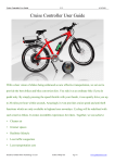
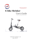
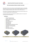
Contents
Getting started…………………………………………………..…. Page 3
Tool List…………………………………………………………… Page 4
Preparing the Back Wheel……………………………………….... Page 5
Installing the Handle bar Components……………………….……. Page 9
Controller Configuration ………………………………………... Page 12
Installation of the controller and battery…………………………. Page 19
PAS installation…………………………………………...…… Page 23
Power Cord installation…………………………………………..Page 24
(With sliding rack and black controller box)
LED Lights Circuit Diagram……………………………………..Page 27
Solution Diagram for Regen Braking……………………………..Page 27
2
Getting started
First, open up the box and lay out the contents inside.
Check that you have:
1) A motorized wheel
2) A controller set
3) A pair of power brakes
4) Twist throttle and Thumb Throttle
Optional items:
1) Battery Pack with adapter
2) Sliding Rack
3) Cruise/Horn Controller
Note: Check for any damage on the
items. Lay out the items on the floor of
your garage and move on to the next
pages to start building your eBike.
3
Tools needed for making your eBike:
Basic Tools
List:
P)
Q)
R)
S)
At least 6 Zip Ties (For holding wires firmly to your bicycle frame)
3 Allen Wrench with diameters 2.5mm, 3.0mm, 6.0mm
Adjustable wrench
Philip Screwdriver
Optional List:
1) Gear removing tools
2) Washers
3) Wire binders
4) Hammer
4
Preparing the Back Wheel (Includes Gear and Disc Brake)
1) Remove the gear cluster from your old back wheel.
Use a Gear-Removing Tool to remove the Gear from your back wheel.
Note: The gear removing tool can be found in your local Bike Shops.
2) Installing the Disc Brake
Install your Disc Brake onto the Wheel.
Note: Please confirm your Disc Brake
diameter. (140mm or 160mm) In most
cases, 140mm Disc Brakes are for the
back wheel whilst 160mm are for the
front wheel.
5
Twist the Disc Brake Plate into position.
Make sure you insert a Disc Brake Plate-Tube into the axle.
Safety Note: The Disc Brake Plate-Tube holds the disc brake in position. It is a very
important component in the Disc Brake System.
Important Note: Usually, the position of the Disc Brake is to the left of the direction
your wheel is travelling. (I.e. The disc brake should be installed on the side where the
Motor Wiring protrudes.)
Note: Use Washers to
adjust the vertical
alignment of the disc
brake.
6
3) Installing the Gear Cluster
Take your preferred Gear Cluster and twist it onto the other side of the Motor.
Note: Golden Motor
Wheels supports most
of 3- to 6-speed gear
clusters.
4) Installing the Tires
First confirm the direction of the thread pattern
of your tire.
Next place one edge of the outer tire into
the rim bedding.
7
Turn the wheel around and fit the
inner tubing’s gas valve into the
opening of the wheel’s rim.
Stuff the rest of the inner
tubing in between the rim
and the outer tubing and
you’re done assembling the
wheel!
Important Note: Please choose an inner tube with a longer valve as Golden Motor
rims are double walled. The rims are double walled to be able to withstand the
powerful torque from the motor.
8
Place the wheel axles into the mount in your bike frame. Push down on the bike frame
to make sure that the wheel axle is locked tightly into the frame. Tighten the bolts;
make sure it is very tight. This is for safety reasons and this is a very crucial step to
build a good eBike. The torque of the motor is very powerful, which is why you must
make sure the bolts are tight enough to handle it. In order for you to remember this
important step, we’ve even made a nice little poem, read it below and we hope that
this will help you remember this every time you build an eBike.
Important GoldenMotor Poem:
Tighten the bolts with all your might,
Make sure the wheel is secured and tight.
The entire back wheel is not very light,
Double check both the bolts on each side.
If anything falls off while you ride
It won’t be a very pleasant sight.
-Yao Yuan
9
Installing the Handle Bars Components
IMPORTANT! : Make sure your handle bar diameter is 22mm
1) Installing the Cruise Control and Horn Switch
(2.5mm Allen Wrench)
Slot the switch into the handle bar.
Note: You can slot it into the side you feel
comfortable with pressing the buttons. The
red button activates the cruise control and
the green button activates the horn.
However, you can also use these buttons
for other purposes you wish for.
Place your hand on the handle bar and find
the ideal position of the switch where your
thumb is able to press the two buttons
comfortably. Then use the 2.5mm Allen
Wrench to tighten it.
Safety Note: Make sure that when your
hand is on the handle bar, your thumb is
able to reach both buttons.
2A) Installing the Thumb Throttle
Pick a type of
speed throttle
you wish to
install.
A- Thumb throttle
B- Twist throttle
Note: If you
already have a
gear shift, then
we suggest
you use the
thumb throttle.
10
Take the mini-tripod and place it in the thumb throttle
as shown.
Note: This tripod comes useful if you are installing the thumb throttle on the right
side of the steering bar. The tripod prevents the edge of the movable ring from getting
stuck when it comes into contact with the exterior handle bars.
Slot the thumb throttle into either side of the
steering bar that you feel comfortable with.
Place your hand on the bar and find
the position where your thumb
feels most comfortable pressing
down on the throttle.
Use the 3.0mm Allen Wrench and tighten the
bolt beneath the throttle.
Safety Note: Make sure that you secure the
throttle onto the bar tightly.
Note: The red button on the throttle is a
switch for you to connect to a lamp if you
have one on your bike or you can use it for
other purposes.
11
2B) Installing the Twist Throttle (Right Side)
Slot the Twist throttle
into the right side of
the bar and get a feel
of twisting the throttle.
When you feel
comfortable with the
position, use the
3.0mm Allen Wrench
and secure it into
place.
3) Installing the Hand Brakes
Slot your hand brakes into both sides of the
steering bar. Place your hand on the bar and find
the position you feel most comfortable with
pressing the brake and then use a 5.0mm Allen
Wrench and secure it into place.
Safety Note: Make sure the brake is
secured tightly as a loose brake may
lead to an accident.
Finally, push the plastic
handle bars into the metal
steering bar tightly and
make sure it is pushed in all
the way.
Note: This Hand Brake
cuts off power supply to the
motor and activates the
mechanical brake
simultaneously
You are now done with
the handle bars!
12
Controller:
Your controller looks something like this. Notice that the controller has 5 single
connectors labeled: A, B, C, D and E and 4 pin-connectors labeled: W, X, Y and Z.
Usually the controller comes with wires already connected to the connectors. If
otherwise, the following will tell you more information about the wires.
The following picture shows how a completely connected controller should look like:
13
Information of your Controller:
1) Four Single wires: Black, Green, Light Blue and Yellow.
2) One 12-hole pin connector with the thicker Red wire connected to a Single
Red Wire labeled with a Positive “+” Sign.
3) One 5-hole pin connector.
4) One 2-hole dual red wire pin connector.
Connecting Wires
* Photos show connection before installing, but you should make these
connections after installing the components
1) The Wheel and Motor:
Single out the Yellow, Light Blue, Green Single wires and the 5-hole Pin connector of
your Controller. Find the 3-hole Pin connector, Green, Blue and Yellow Single Wires
of your Motor.
Next, take the motor’s wires and connect them like so:
Safety note:
Make sure you hear a “Click”
sound when you connect the
pin connectors.
14
2) The Horn:
Take the Horn and connect it
to the 2-hole pin connector.
3) The Battery:
Take your controller and plug in the Black Single Wire and the Red Single Wire. The
outer ends of these 2 wires should have been labeled with positive or negative signs.
Take the Battery Pack’s wires and connect them accordingly.
Safety note:
Make sure that you have
connected the wires correctly
before turning on the power.
If unsure, use a Voltmeter to
confirm the poles are correct.
It is IMPORTANT to connect
them correctly as a short circuit
may occur.
Disclaimer: GoldenMotor will
not be responsible for any
damage caused to the controller
if a short circuit occurs.
15
4) The Throttle:
Take the throttle wire and single out the 3-hole pin connector.
Take the 3-hole pin connector (Blue, Black, Red) from the controller area Z and plug
them together.
Safety Note:
Make sure you hear a “Click” sound when you connect them. If not your motor would
not work.
16
5) The Brakes:
Find the 2-pin connector (Black and White wires) from area Z and plug it into the
Brake wire.
Note: This brake does not control the disc brakes on your wheel, it only cuts out the power
supply to the motor. You would have to connect this brake to your disc brake manually. By
squeezing the brake, the controller enters regenerative braking mode for smooth stopping.
6) Cruise Speed Control:
Find the 2-hole pin connector (Beige and Black wires) and plug it into your Cruise
Control system.
17
7) PAS (Pedal Assistance System ):
For customers who opted for PAS, plug your PAS 2-hole pin connector into area Y
Note: Power ON the pedelec by pressing the Cruise Control Button twice. Power it
OFF by cutting off the power supply to the controller. The Pedelec function is made
this way so that only intentional use is allowed for safety reasons.
Wiring Information:
For more detailed information, please visit this website link:
http://goldenmotor.com/e-Bike-DIY/Cruise%20Controller%20Wiring%20Diagram.pdf
How to Enable/Disable these Functions/Features?
1. Cruise speed control:
Pressing the cruise control button will make your eBike maintain the speed you
are currently at. Squeezing the brakes or pressing the cruise control button again
will disable it.
2. Motor hall-sensor malfunctions:
When the controller detects a motor hall-sensor failure, it will beep twice before
automatically entering into sensor-independent control mode. Twist/press the
throttle to run the motor and pedal your bike for a push start if the motor does not
operate. (This malfunction seldom happens in a state of sensor-independent
control status)
3. Throttle malfunctions:
When the throttle fails to function correctly, the controller will beep three times.
In this situation, press and hold the cruise control button to drive your bike at half
the maximum speed. The controller will automatically return to its original status
when the problem is resolved.
18
4. Power-brake lever malfunction:
If the power-brakes level malfunctions ( i.e. disconnected from the controller),
twist/press the throttle repeatedly for at least four times. The controller will then
beep four times if this malfunction is detected. Similarly, press and hold the cruise
control button to drive your bike at half the maximum speed. The controller will
automatically return to its original status when the problem is resolved.
5. Unknown malfunctions:
If your eBike fails to move and the cause is unknown or if your battery is low, you
can force your eBike to work. While squeezing the power-brakes, press the cruise
control button five times and if you hear the honk from your horn, press and hold
the cruise control button again and you can drive your bike at half speed. You will
need to turn off the battery power to reset the controller back to normal mode after
the problem is resolved.
6. Anti-theft alarm setting:
Cut off power supply to motor (called soft-switch, but controller is still powered
on) and take out the battery key, within 10 seconds press and hold the cruise
control button until you hear a beep sound, then release the cruise control button.
The vehicle is now protected from theft and the motor is electronically locked.
Any movement or vibration of vehicle will trigger the siren for 30 seconds, and
the motorized wheel will resist any pedaling movement.
7. 1+1 Pedal Assist Mode:
Release the throttle to its neutral position during riding, press cruise speed
controller button twice, listen a beep sound, the system enters into pedelec (PAS)
mode. Cut off power supply to the controller to reset this system.
8. Motor phase Calibrating (Use it only if your motor is not from
GoldenMotor):
The controller can work brushless motors with different phase angles other than
defaulted 120 degree. Below are procedures to allow the controller to match the
motor phases:
z
z
z
z
z
z
Cut-off power to controller and motor
Grip and hold power brake lever, turn throttle to maximum speed position,
press and hold the cruise control button, turn on the power switch (using
battery key)
Connect battery power to the system, release throttle, release brake lever,
release cruise control button.
Listen for two beep sounds, then turn the motor wheel forward and reverse
once.
When you hear a beep sound, motor phase calibrating is successful.
If it fails, swap any two of the three motor phase wires, and repeat the above
steps.
19
Installation of the Controller and Battery
1) Controller Box
Place the controller into the box and secure it with tape or screws.
Note: Controller
boxes will be on
sale in June 2009 on
the GM website.
Safety Note: Make
sure you secure the
components in the
box properly.
2) Sliding Rack
Fix your Sliding rack onto your bicycle. However, do not tighten the screws as we
need to put in the controller box later.
Note: These frames are purchasable at
the Golden Motor website under the
category eBike D.I.Y.
Note: Make sure your box can fit
onto the sliding rack.
20
3) Wire binding
Bind the wires using Zip Ties in a way
such that it does not restrict the movement
of the steering bar. Find ways to lock all
the wires onto your bicycle frame such
that they are not very visible. Also secure
the brake threads to your front and back
brakes accordingly.
Note: As a suggestion, after you bind your wires, rotate your bike handles to see if the
movement is smooth.
4) Connecting the wires to your controller
Refer to the guide on the Controller and connect your wires to the controller
accordingly.
21
Use Zip Ties or anything else you prefer to secure the controller box onto the sliding
frame.
Note: You can place the controller box wherever you feel like as long as the wires are
long enough to connect to it.
5) Battery placement
Slide the battery pack onto the sliding rack
with the battery’s handle bar facing
backwards.
Plug the cable in but do not twist
the key.Proceed to the final
checklist before testing your bike.
Safety note: Make sure the battery is turned off before you even plug in the power
cable.
22
6) Finishing the fight
Checklist: (Turn off the battery)
1)
2)
3)
4)
5)
6)
7)
8)
9)
Wheel is secured in place.
Back wheel is vertically aligned with front wheel.
Wheel has no loose parts.
All components on the handle bar have been secured tightly.
You are comfortable with the throttle, brakes, etc.
The handle bar is able to rotate freely.
The mechanical brakes work properly.
The battery cannot slide off without unlocking it.
Check that the battery poles are connected correctly.
If there are no problems, then turn on the battery, lift up the rear end so that the rear
wheel is not touching the floor, start the throttle to test the wheel.
Congratulations!
You have completed your own custom made Electric Bicycle
Important Note: While using regenerative braking, DO NOT turn off the battery.
23
PAS Installation
PAS (Pedal Assistance System), also known as pedelec system, is a compulsory
component of an electric vehicle in European countries. The system controls the
amount of electricity supplied to the motor proportional to the angular velocity of the
pedal. (i.e. the faster you pedal, the faster the motor turns.)
After removing the the pedal crank arm,
place the receiver ring into the axle and
secure it in position using washers or
superglue.
Place the outer magnetic ring next to
the inner ring. Make sure they do not
have any contact in between using
washers.
Screw back the pedal into place, connect
the PAS wire with the controller and you
are ready to ride legally in Europe.
24
Power cable installation guide
(If you purchased our sliding rack and controller box)
To make sure our power cord is
connected securely to the battery, we
have made extra measures to ensure this,
however the procedure is also made
more difficult. Hence follow this guide
to beat this tricky installation part.
You should have:
1)The sliding rack
2)The Black Controller box
3)Black connector
4)Plastic connector-protector
5)Power cord
The point is to get the wires
through one of these two holes.
Therefore we sent you items 3,4
and 5 separately as item 5 must
be thin enough to go through this
hole.
First, slide the power cable
through the controller box’s
hole as shown on the right.
25
Next, take one of the two
power cables and bend it
as shown.
Slide in the unbent cable
into the protector.
After the wire has been
pushed through, push the
bent wire in as well, this
is because the neck of the
protector is not big
enough to fit both at the
same time.
When both power cords
go through, push the
protector all the way back.
26
Look closely at the ends of the
power cord, it looks like a talon.
Keep in mind that this is
designed to be a talon, like a
giant-ass eagle that wants to
claw and grip onto the
connector.
Watch out for the “+/-” signs
on the connector, make sure
Red goes into + and black goes
into - . Push all the way in until
you hear a click sound.
Make sure the “Nails of the
Talon” has reached the end and
clipped onto the metal plate. If
this is done correctly, it is
nearly impossible to pull out
the power cord without tools.
Slide back the protector and
Voila! You’re done, grab a
beer to congratulate yourself.
(Or if you are a minor, get
some Pepsi instead)
27
28
Resolved Case: Burnt out Controller by regenerative braking.
Important!
When you turn off the battery and continue riding by pedaling, using the regenerative braking may burn
out your controller.
The current generated from the regenerative braking flows into the battery under normal circumstances.
However if you turn off the battery, the current gets trapped inside the controller and if the current is too large,
it will burn the controller. Hence, GoldenMotor engineers will place a diode inside as shown in the circuit
diagram above as of July 6th 2009. Users, who ride our bike in terrains that contain steep slopes, please ensure
that your battery is always turned on. If you have experience in engineering, please install a diode of rating
100V 20A inside the battery pack according to the diagram above.
When the battery/switch is turned off, the current generated by the regenerative braking will still flow
into the positive terminal, charging the battery. However the electrical energy from inside the battery itself
cannot flow out due to the diode. This basically solves most issues for riders who live in mountainous regions
with hills or slopes steeper than 10degrees. For riders who live in places with flat terrains, this is not a necessity.
For your own safety and for the controller’s safety, please ensure that your battery is always turned on
unless you have installed this diode.
GoldenMotor batteries will all be equipped with this diode from July 6th 2009 onwards. Hence, for users
who are using batteries from other sellers or have bought GoldenMotor batteries before the 6th of July, please
take note of this issue.
Many thanks to Gregory McIntire, a GoldenMotor customer whom brought up, brainstormed and resolved this issue.
29
Written and editied by:
GM:Yao Yuan
Tom
Update contributors:
Duane Smeckert
Gregory McIntire
30