1
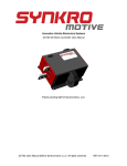
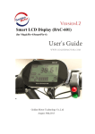
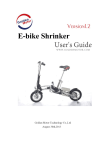
 High Power BLDC Controller User Guide
HPC Series Brushless DC Motor Controller User Guide Golden Motor HPC series motor controllers are specially designed for high power, high reliability brushless DC motor drive for electric vehicles, boats, and industrial applications. The controller is using the cutting edge technologies to deliver smooth and robust control experiences. The controllers are manufactured with high quality components and materials for high end users. The casing is completely sealed to meet IP66 protection. The optional programming kit (using PC USB port) is available for expert users to setup control parameters for their special applications. Key Features: ★ Suitable for brushless DC motors
★ Low noise,little torque fluctuation
★ Maximum efficient >98%,high reliability
★ IP66 Protection
★ 23-pin waterproof Connector
★ Regenerative Braking
★ Slope holding control
★ Cruise speed control
★ Over heat protection for both motor and controller
★ Programmable via USB of PC/Laptops
★ Programmable motor temperature limit
★ DSP control
★ ★
Support CAN port (optional)
Dual controller synchronous drive
HPC300H Series HPC500H Series HPC700H Series Page: 11‐1 Golden Motor Technology Co Ltd. www.goldenmotor.com High Power BLDC Controller User Guide
z
Product Specifications
Model HPC300H Series HPC500H Series HPC700H Series z
HPC300H48360 HPC300H72300 HPC300H96240 HPC500H48600 HPC500H72500 HPC500H96400 HPC700H48840 HPC700H72700 HPC700H96560 Peak input current 180A 150A 120A 300A 250A 200A 420A 350A 280A Peak Output current(1min) 360A 300A 240A 600A 500A 400A 840A 700A 560A Voltage of Battery Pack 48V 72V 96V 48V 72V 96V 48V 72V 96V Cooling Condition External cooling Product functions
HPC Series Item Controller temperature protection 70~90ºC: limit current output to prevent the controller from over‐heat and damage. >90ºC: controller will self‐shutdown Motor temperature protection Programmable temperature limit. If the motor temperature hit the limit, controller will lower the output current to motor to prevent motor from over‐heat or damage motor parts. (It works only when motor temperature sensor is presented) Regenerative Braking (Energy Transforming kinetic energy of vehicle into electricity to charge feedback) the battery when Brake is shorted to “GND” or Brake is “12V”, charging current and voltage are programmable via USB programmable interface. Brake control Stop motor drive, regenerative braking starts. FWD/REV control Control the motor rotation direction between forward and reverse Cruise control Button switch: Depress the switch to start cruise speed mode Release the button to cancel cruise mode, or cruise control function is cancelled whenever brake is “ON” or “FWD/REV” switch changes. Note: If accelerator control speed is higher than cruise control speed, accelerator control is in effect. If accelerator control speed is lower than cruise control speed, accelerator control is not in Page: 11‐2 Golden Motor Technology Co Ltd. www.goldenmotor.com High Power BLDC Controller User Guide
effect. Optional: When parking or start on slope, the vehicle does not slip. Slope holding control z
Alarm status output by USB or CAN
Alarm status display High Voltage Shutdown Low Voltage Shutdown Voltage low limited speed to 50% Voltage low limited speed to 15% Controller shutdown at high temperature Controller limits current output at high temperature of controller Controller limits current output at high temperature of motor Current Shutdown of DC Contactor1(PIN3) Actions to rectify Check and reset parameter <Voltage High Shutdown> value setting, then restart controller Check and reset <Voltage Low Shutdown> value setting, or charge battery pack Check and reset <Voltage Low1> value setting, or charge battery pack. Check and reset <Voltage Low2> value setting, or charge battery pack. Cooling controller or check heat sink, then restart controller. Cooling controller or check heat sink. Check and adjust <motor off(C)> value or cool the motor Check Line contractor coil(PIN2, PIN3) Current Shutdown of DC Contactor2(PIN4) Check fan contractor coil(PIN2, PIN4) Current Shutdown of DC Contactor3(PIN5) Check reverse contractor coil(PIN2, PIN5) Motor Hall Error Check hall sensor wire of motor and connector or motor hall sensor Phase Current Over Shutdown Check phase wire of motor Check coil wire of motor Check controller output current Stall of Motor Shutdown Reset phase current value Check position sensor of motor Motor shaft is braked Accelerator Output Voltage High Shutdown (PIN7) Check accelerator GND(PIN8) wire, connector or accelerator Page: 11‐3 Golden Motor Technology Co Ltd. www.goldenmotor.com High Power BLDC Controller User Guide
z
Wiring diagram HPC H Series Motor Controller Wiring Diagram Page: 11‐4 Golden Motor Technology Co Ltd. www.goldenmotor.com High Power BLDC Controller User Guide
z
23‐PIN Connector Pin Numbering z
PIN Connector Pin Definition and Description Function PIN Symbol Numerical value Power input 1 PWR Batteries Voltage Contractor + 2 CON Batteries Voltage Line contactor 3 CON1 24~48V winding of line control contactor Fan contactor 4 CON2 24~48V winding of contactor control 2 Reserve contactor 5 CON3 24~48V winding of contactor control 3 PWR 6 +5V PWR +5V Accelerator 7 Acc Accelerator signal Sensor GND 8 GND GND FWD/REV 9 FWD/REV “GND” FWD Brake 10 BAK “GND” True Cruise control 11 Cruise control “GND” True Hybrid control 12 Hybrid control “GND” True Brake 13 BAK “12V” True RXD 14 RXD RXD TXD 15 TXD TXD CAN H 16 CAN H CAN H CAN L 17 CAN L CAN L Motor sensor 18 Ha/SIN Hall a/SIN Motor sensor 19 Hb/COS Hall b/COS Motor sensor 20 Hc/AGND Hall c/AGND PWR 21 +5V PWR +5V GND 22 GND GND Motor TEMP 23 Motor Motor TEMP temperature Ipeak <10A Ipeak <10A Ipeak <1A Button switch 0~15V Input Ipeak <1A Silicon temperature sensors: KTY84‐130 Page: 11‐5 Remarks Pre‐charge Ipeak <10A Golden Motor Technology Co Ltd. www.goldenmotor.com High Power BLDC Controller User Guide
HPC300H series Motor Controller Dimensions (weight 2.2kg): Page: 11‐6 Golden Motor Technology Co Ltd. www.goldenmotor.com High Power BLDC Controller User Guide
HPC500H series Motor Controller Dimensions (weight 2.9kg): Page: 11‐7 Golden Motor Technology Co Ltd. www.goldenmotor.com High Power BLDC Controller User Guide
HPC700H series Motor Controller Dimensions (weight 5.7kg): Page: 11‐8 Golden Motor Technology Co Ltd. www.goldenmotor.com High Power BLDC Controller User Guide
z Connect with accelerator Accelerator output value can be with linear output or index output, use USB programmer software setup. 1. Connect with Hall Sensor Accelerator Initial value(mv) Typical value 800 range Final value(mv) 4500 2000~4500 Threshold(mv) 4900 4600~5000 650~1200 2. Connect with 3‐wire Resistor Sensor Accelerator Typical range value Initial value(mv) 100 50~1200 Final value(mv) 4100 2000~4100 Threshold(mv) 4500 4500~4900 Note: External resistor (1K ohms) to prevent GND disconnect automatically run of the vehicle. 3. Connect with 2‐wire Resistor Sensor Accelerator Typical range value Initial value(mv) 100 50~1200 Final value(mv) 4100 2000~4100 Threshold(mv) 4500 4500~4900 Note: External resistor (1K ohms) to prevent GND disconnect automatically run of the vehicle. Page: 11‐9 Golden Motor Technology Co Ltd. www.goldenmotor.com High Power BLDC Controller User Guide
Connect with motor temperature sensor Motor temperature sensor Type: KTY84‐130 Range: ‐40~300ºC z Connect with motor hall position sensors Controller Motor Motor Color Pin 18 Hall a/sin Blue Pin 19 Hall b/cos Green Pin 20 Hall c/AGND Yellow Pin 21 +5V Red Pin 22 GND Black z Connect with contractor contactor coil voltage contactor coil voltage setup
36Vdc 48Vdc 72Vdc Page: 11‐10 24V or 36V 36 or 48V 48V Golden Motor Technology Co Ltd. www.goldenmotor.com High Power BLDC Controller User Guide
z
z
z
When the Power On, Self Test is normal, about 600ms, after the controller start line contractor. When the controller temperature >30℃, after the controller start Fan contractor. When the FWD/REV is REV, after the controller start Reverse contractor. Connect with Brake or Brake z
Brake: When the brake switch is closed, the motor feedback energy to the battery accordance with setup voltage and current. Brake: When the brake switch is closed, the motor feedback energy to the battery accordance with setup voltage and current. or Brake: When the brake signal changes, the motor feedback energy to the battery accordance with setup current scaled changes. Page: 11‐11 Golden Motor Technology Co Ltd. www.goldenmotor.com