1
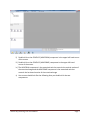
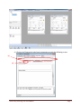
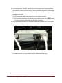
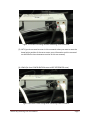
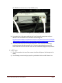
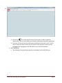
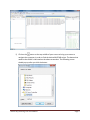
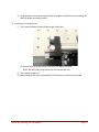
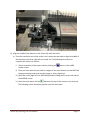
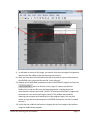
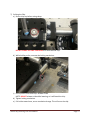
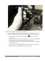
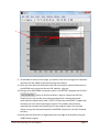
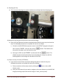
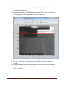
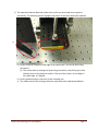
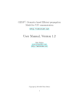
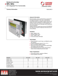
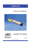
 Montana State University College of Engineering Department of Electrical and Computer Engineering Silicon Chip Cleaving Tool
User Manual Michael Martin, Daniel Chern 12/2/2011 Silicon Chip Cleaving Tool User Manual Page 1 1) Ensure USB port is plugged in to computer with camera and 2 CONEX‐CC controllers connected 2) Ensure CONEX‐CC controller power source is plugged in 3) Open the needed software programs a) NSTRUCT (program used to control the two motorized axes) i) Icon: b) uc480 Viewer (program used to view the camera and take screenshots) i) Icon: c) MATLAB (program used for image processing) i) Icon: 4) Initialize the components in the programs a) NSTRUCT i) The following screen should pop up after you double‐click the NSTRUCT icon: Silicon Chip Cleaving Tool User Manual Page 2 ii) Double‐click on the CONEX‐CC (A6UCP9JM) component in the upper left hand corner of the screen. iii) Double‐click on the CONEX‐CC (A6UCP9ME) component in the upper left hand corner of the screen. iv) The A6UCP9JM component is the motorized axis that controls the vertical motion of the motorized stage and the A6UCP9ME component is the motorized axis that controls the horizontal motion of the motorized stage v) Your screen should look like the following after you double‐click the two components: Silicon Chip Cleaving Tool User Manual Page 3 vi) Click on the ‘Diagnostics’ tab of each component to reach the following screen: (1) (2) Silicon Chip Cleaving Tool User Manual Page 4 vii) In the text box after a specific set of instructions need to be entered into the text box in order to initialize each DC Servo Controller component. The following instructions that need to be done in order to enter in commands are diagramed on the above screenshot. (1) The commands need to be entered one by one into the text box. (2) Once you have entered a command line, you need to click on the button in order to send the command to the DC Servo Controller. viii) The commands that need to be entered in order are as follows (*NOTE: Command are not case sensitive): (1) 1RS (issues a hardware reset of the controller) Figure: LED state is solid orange before and after executing 1RS command. (2) 1PW1 (Go from NOT REFERENCED state to CONFIGURATION state) Silicon Chip Cleaving Tool User Manual Page 5 Figure: LED status is blinking red after executing 1PW1 command. (3) 1HT1 (you do not need to enter in this command unless you want to reset the home/origin position of the servo motor, more information on this command can be found in the maintenance section of this user manual) (4) 1PW0 (Go from CONFIGURATION state to NOT REFERENCED state) Figure: LED state is solid orange after executing 1PW0 command. Silicon Chip Cleaving Tool User Manual Page 6 (5) 1OR (Starts the execution of the HOME search) Figure: LED status is solid green after executing 1OR command. ix) A complete list of the commands that the Servo Controller recognizes and more details on the commands can be found at the following URL: ftp://download.newport.com/MotionControl/Current/MotionControllers/CONEX/M
anual/CONEX‐CC/CONEX‐CC%20‐%20Controller%20Documentation.pdf x) The status and color of the LED on the physical DC Servo Controller component indicate the state that the controller is in. If you are not getting the correct LED status and color then refer to the above URL to troubleshoot/diagnose the problem. b) uc480 Viewer i) The LED located on the top of the camera should be solid green, indicating that it is ready. ii) The following screen should pop up after you double‐click the uc480 Viewer icon: Silicon Chip Cleaving Tool User Manual Page 7 iii) iii) Click on the icon in the top left corner of the screen in order to open the camera view. The icon that needs to be clicked is indicated on the above screenshot. iv) Once you click on the icon the camera view should show up on the screen. If this is not the case make sure to check the LED status on the top of the camera and try unplugging and replugging in the USB cable to try to solve the problem. c) MATLAB R2011a i) The following screen should pop up after you double‐click the MATLAB icon: Silicon Chip Cleaving Tool User Manual Page 8 ii) Click on the button at the top‐middle of your screen to bring up a screen to navigate the computer in order to find the desired MATLAB scripts. The button that needs to be clicked is indicated on the above screenshot. The following screen should pop up after you click the button. Silicon Chip Cleaving Tool User Manual Page 9 iii) Once the above screen pops up you need to navigate to the directory containing the MATLAB image processing scripts. 5) Load chip onto clamping arm i) Turn Screw clockwise to secure chip snugly onto clamp (1) Ensure screw is no more than 5mm from the edge of the chip NOTE: DO NOT clamp chip too hard as it will break the chip. ii) Turn rotation stage to 0o iii) Move clamping arm across translational rail till feature is within camera range Silicon Chip Cleaving Tool User Manual Page 10 6) Align the middle of the feature on the silicon chip with the scribe a) Since the translation axis of the scribe is set in place then we need to align the middle of the feature on the silicon chip with the scribe axis. The following instructions to complete this task are as follows. i) Take a screenshot of the camera view by clicking the button in the uc480 Viewer screen. ii) Once you have done this you need to navigate to the same directory as the MATLAB image processing scripts and save the image as ‘scibe_align.bmp’. iii) Open the scribe_align.m file in MATLAB by double‐clicking the file on the left side of the MATLAB screen. iv) Once the script opens click the button at the top of the screen to run the script. The following screen should pop up after you click the button: Silicon Chip Cleaving Tool User Manual Page 11 1. 2. v) As indicated at the top of the image, you need to click the inner edge of the platform and then click the middle of the feature using the crosshair. vi) Once you have done this the distance that the chip needs to move will be output to the MATLAB main screen and the text file ‘scribe_align.txt’. vii) Now go to the A6UCP9ME component screen in the NSTRUCT program and click the button to find the ‘scribe_align.txt’ output text file from. Double‐click on the text file once you have navigated to it and the horizontal motorized axis should have moved. (*NOTE: On occasion the NSTRUCT program will encounter an error when importing the text file. The problem was solved by restarting the computer and reopening all of the programs again. You may also choose to copy the command output from MATLAB and paste it into the Command text box.) viii) Verify that the middle of the feature is aligned with the inner edge of the platform using the uc480 Viewer program. Silicon Chip Cleaving Tool User Manual Page 12 7) Scribing the Chip a) Secure chip to platform using clamp. DO NOT CLAMP THE CHIP TOO HARD as it will break the chip. b) While holding scribe, unscrew the locking mechanism. c) Gently lower scribe onto chip. Release scribe. NOTE: DO NOT release scribe while lowering, as it will break the chip d) Tighten locking mechanism e) Pull scribe toward user, across translational stage. This will score the chip. Silicon Chip Cleaving Tool User Manual Page 13 8) Align the scribe mark with the inner edge of the platform a) We need to align the scribe mark with the inner edge of the platform in order to ensure optimal chip breaking. The following instructions to complete this task are as follows. i) Take a screenshot of the camera view by clicking the button in the uc480 Viewer screen. ii) Once you have done this you need to navigate to the same directory as the MATLAB image processing scripts and save the image as ‘platform_align.bmp’. iii) Open the platform_align.m file in MATLAB by double‐clicking the file on the left side of the MATLAB screen. iv) Once the script opens click the button at the top of the screen to run the script. The following screen should pop up after you click the button. Silicon Chip Cleaving Tool User Manual Page 14 1. 2. v) As indicated at the top of the image, you need to click the inner edge of the platform and then click the middle of the feature using the crosshair. vi) Once you have done this the distance that the chip needs to move will be output to the MATLAB main screen and the text file ‘platform_align.txt’. vii) Now go to the A6UCP9ME component screen in the NSTRUCT program and click the button to find the ‘platform_align.txt’ output text file from. Double‐click on the text file once you have navigated to it and the horizontal motorized axis should have moved. (*NOTE: On occasion the NSTRUCT program will encounter an error when importing the text file. The problem was solved by restarting the computer and reopening all of the programs again. You may also choose to copy the command output from MATLAB and paste it into the Command text box.) viii) Verify that the scribe mark is aligned with the inner edge of the platform using the uc480 Viewer program. Silicon Chip Cleaving Tool User Manual Page 15 9) Breaking the Chip a) Turn screw on clamping arm counter‐clockwise to unclamp chip from clamping arm. 10) Break the chip using the vertical axis of the motorized stage a) Once all of the alignment has been completed and verified the next step is to break the chip. The following instructions to complete this task are as follows. i) Go back to the A6UCP9JM component screen in the NSTRUCT program and type in 1PR‐2 into the text box and click the the vertical axis down 2mm and break the chip. button. This should move text box and click the button. This ii) Now type in 1PR2 into the should move the vertical axis back up 2mm and realign the clamp arm with the breaking platform and realign the two halves of the chip. 11) Check accuracy of cleave (*OPTIONAL) a) If you choose to check how accurate the design was able to cleave the chip, the following instructions to complete this task are as follows. i) Take a screenshot of the camera view by clicking the button in the uc480 Viewer screen. ii) Once you have done this you need to navigate to the same directory as the MATLAB image processing scripts and save the image as ‘check_accuracy.bmp’. Silicon Chip Cleaving Tool User Manual Page 16 iii) Open the check_accuracy.m file in MATLAB by double‐clicking the file on the left side of the MATLAB screen. iv) Once the script opens click the button at the top of the screen to run the script. The following screen should pop up after you click the button: 2. 1. v) You may to click either the scribe mark or the middle of the feature using the crosshair. vi) Once you have done this the distance between the scribe mark and the middle of the feature will be output to the MATLAB main screen and the text file ‘check_accuracy.txt’. 12) Maintenance Silicon Chip Cleaving Tool User Manual Page 17 a) Earlier in the instructions to initialize the components in the NSTRUCT program, it was mentioned that you may use the 1HT1 command to set the home position of each motorized axis. The details of this step will be explained here. i) Before you issue the home set command make sure that the position that you have the two motorized axes positioned at the home location that you desire. (1) Since most of the movement is relative, the user can move the axes relative to the current position (can be checked using the 1PR? Command) can then setting the current position to the home position using the 1PW1, 1HT1, 1PW0, 1OR sequence. ii) Once the motors are in the desired home position, type in the same sequence of commands in the initialization section including the 1HT1 command. For your convenience the commands are as follows: (1) 1RS (2) 1PW1 (3) 1HT1 (4) 1PW0 (5) 1OR b) There are also other minor maintenance issues that need to be checked from time to time. These details of these issues are as follows. i) There is tape on the chip breaking platform for the purpose of alignment assistance and in order to prevent damage to the chip. This tape needs to be periodically replaced as it will wear down and basically become useless in not maintained. Silicon Chip Cleaving Tool User Manual Page 18 ii) The tape that holds the diamond scribe to the scribe arm also needs to be replaced periodically. The following picture highlights the pieces of tape that need to be replaced.
i) ii) iii) Ensure scribe tip is aligned to the edge of the yellow tape. This can be done using the camera. (1) This can be done by viewing the layout using the camera, and placing the scribe relatively close to the platform surface. If the tip of the scribe is on the edge of the yellow tape, it is aligned. iv) Ensure platform height is the same as the clamping arm. v) The rubber band on the locking mechanism may need to be replaced periodically. Silicon Chip Cleaving Tool User Manual Page 19