1
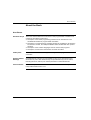
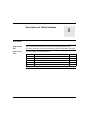
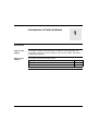
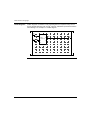
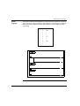
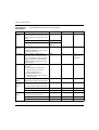
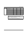
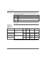
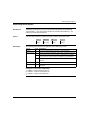
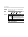
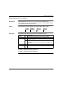
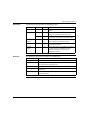
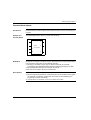
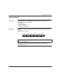
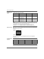
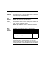
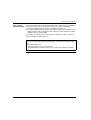
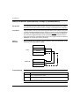
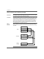
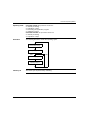
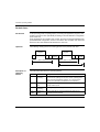
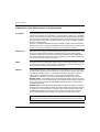
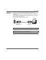
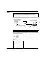
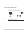
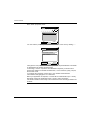
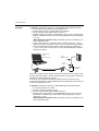
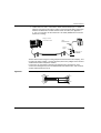
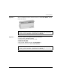
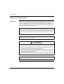
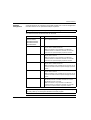
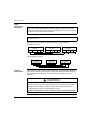
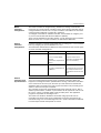
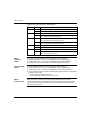
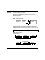
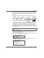
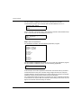
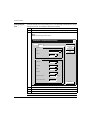
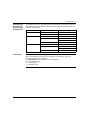
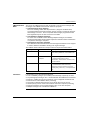
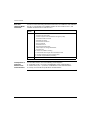
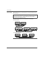
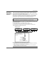
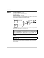
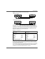
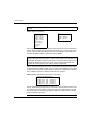
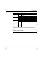
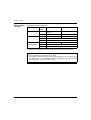
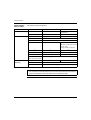
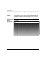
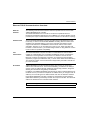
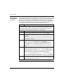
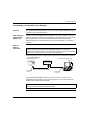
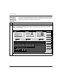
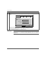
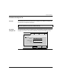
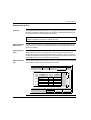
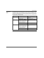
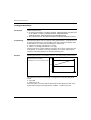
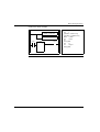
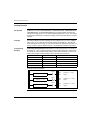
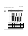
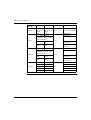
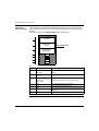
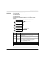
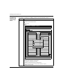
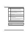
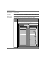
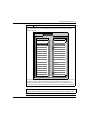
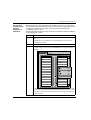
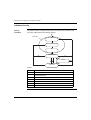
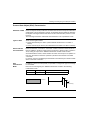
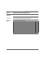
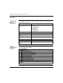
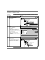
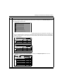
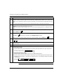
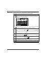
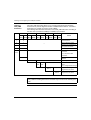
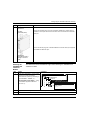
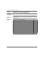
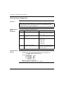
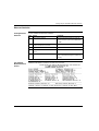
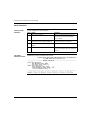
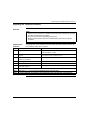
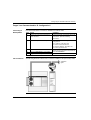
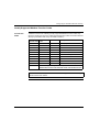
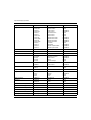
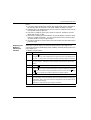
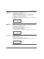
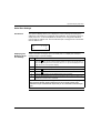
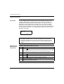
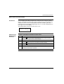
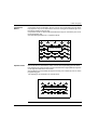
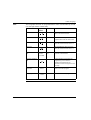
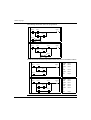
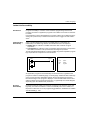
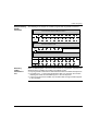
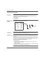
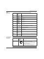
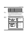
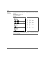
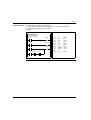
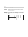
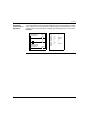
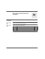
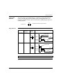
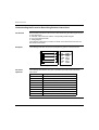
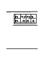
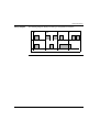
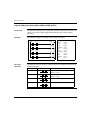
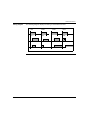
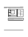
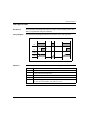
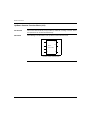
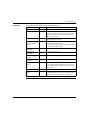
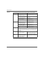
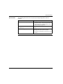
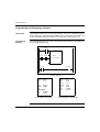
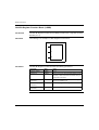
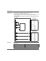
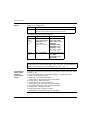
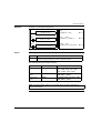
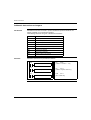
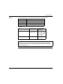
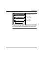
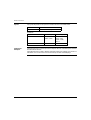
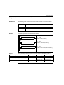
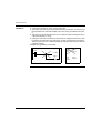
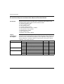
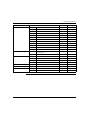
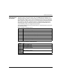
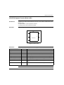
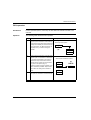
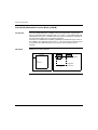
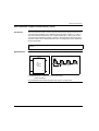
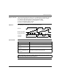
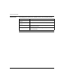
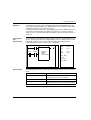
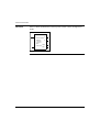
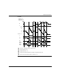
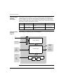
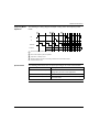
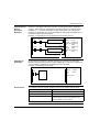
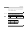
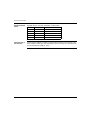
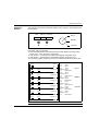
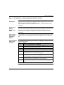
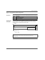
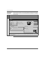
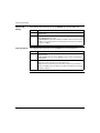
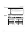
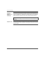
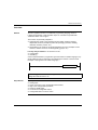
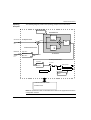
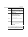
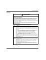
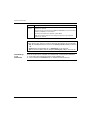
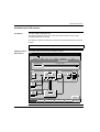
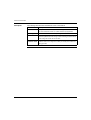
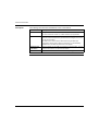
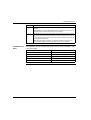
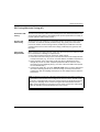
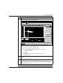
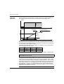
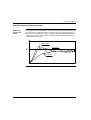
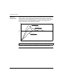
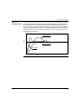
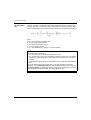
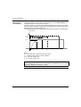
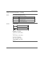
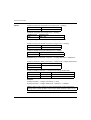
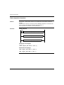
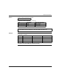
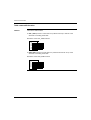
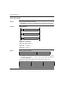
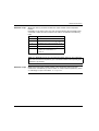
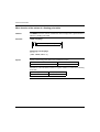
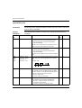
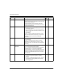
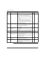
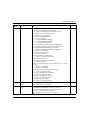
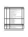
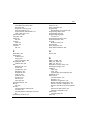
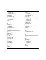
Communications
Remote Link
Example
To configure a Remote Link, you must:
1. Configure the hardware.
2. Wire the controllers.
3. Connect the communications cable between the PC to the controllers.
4. Configure the software.
5. Write an application.
The diagrams below illustrate the use of the remote link with remote I/O and a peer
controller.
Step 1: Configure the Hardware:
I0.0
Remote I/O
Master controller
I0.1
Q0.0
Peer controller
Q0.1
The hardware configuration is three base controllers of any type. Port 1 is used for
two communication modes. One mode is to configure and transfer the application
program with TwidoSoft. The second mode is for the Remote Link network. If
available, an optional Port 2 on any of the controllers can be used, but a controller
only supports a single Remote Link.
Note: In this example, the two first inputs on the Remote I/O are hard wired to the
first two outputs.
Step 2: Wire the controllers
Mini-DIN connection
Master
controller
A(+) B(-) GND DPT
1
2
7
5
Remote controller
Peer controller
...
Address 1
Address 2
A(+) B(-) GND DPT
A(+) B(-) GND DPT
Terminal block connection
Master
controller
A(+) B(-) 0V
A
112
B
SG
Remote controller
...
Address 1
A(+) B(-) 0V
Peer controller
Address 2
A(+) B(-) 0V
TWD USE 10AE