1
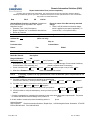
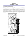
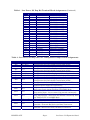
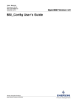
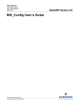
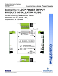
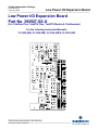
Product Information Package
PIP-EXP I/O TF
February, 2008
Low Power I/O Expansion Board
Low Power I/O Expansion Board
Part No. 392927-XX-X
(For TeleFlow Plus, TeleRTU Plus, TeleRTU Module & TeleRecorder)
For the following Instruction Manuals:
CI-3530-20B, CI-3530-25B, CI-3530-35B & CI-3530-55B
Remote Automation Solutions
www.EmersonProcess.com/Remote
IMPORTANT! READ INSTRUCTIONS BEFORE STARTING!
Be sure that these instructions are carefully read and understood before any operation is
attempted. Improper use of this device in some applications may result in damage or injury. The
user is urged to keep this book filed in a convenient location for future reference.
These instructions may not cover all details or variations in equipment or cover every possible
situation to be met in connection with installation, operation or maintenance. Should problems arise
that are not covered sufficiently in the text, the purchaser is advised to contact Emerson Process
Management, Remote Automation Solutions division (RAS) for further information.
EQUIPMENT APPLICATION WARNING
The customer should note that a failure of this instrument or system, for whatever reason, may
leave an operating process without protection. Depending upon the application, this could result in
possible damage to property or injury to persons. It is suggested that the purchaser review the
need for additional backup equipment or provide alternate means of protection such as alarm
devices, output limiting, fail-safe valves, relief valves, emergency shutoffs, emergency switches,
etc. If additional information is required, the purchaser is advised to contact RAS.
RETURNED EQUIPMENT WARNING
When returning any equipment to RAS for repairs or evaluation, please note the following: The
party sending such materials is responsible to ensure that the materials returned to RAS are clean
to safe levels, as such levels are defined and/or determined by applicable federal, state and/or
local law regulations or codes. Such party agrees to indemnify RAS and save RAS harmless from
any liability or damage which RAS may incur or suffer due to such party's failure to so act.
ELECTRICAL GROUNDING
Metal enclosures and exposed metal parts of electrical instruments must be grounded in
accordance with OSHA rules and regulations pertaining to "Design Safety Standards for Electrical
Systems," 29 CFR, Part 1910, Subpart S, dated: April 16, 1981 (OSHA rulings are in agreement
with the National Electrical Code).
The grounding requirement is also applicable to mechanical or pneumatic instruments that
include electrically operated devices such as lights, switches, relays, alarms, or chart drives.
EQUIPMENT DAMAGE FROM ELECTROSTATIC DISCHARGE VOLTAGE
This product contains sensitive electronic components that can be damaged by exposure to an
electrostatic discharge (ESD) voltage. Depending on the magnitude and duration of the ESD, this
can result in erratic operation or complete failure of the equipment. Read supplemental document
S14006 at the back of this manual for proper care and handling of ESD-sensitive components.
Remote Automation Solutions
A Division of Emerson Process Management
1100 Buckingham Street, Watertown, CT 06795
Telephone (860) 945-2200
WARRANTY
A.
Remote Automation Solutions (RAS) warrants that goods described herein and manufactured by RAS are
free from defects in material and workmanship for one year from the date of shipment unless otherwise
agreed to by RAS in writing.
B.
RAS warrants that goods repaired by it pursuant to the warranty are free from defects in material and
workmanship for a period to the end of the original warranty or ninety (90) days from the date of delivery of
repaired goods, whichever is longer.
C.
Warranties on goods sold by, but not manufactured by RAS are expressly limited to the terms of the
warranties given by the manufacturer of such goods.
D.
All warranties are terminated in the event that the goods or systems or any part thereof are (i) misused,
abused or otherwise damaged, (ii) repaired, altered or modified without RAS consent, (iii) not installed,
maintained and operated in strict compliance with instructions furnished by RAS or (iv) worn, injured or
damaged from abnormal or abusive use in service time.
E.
These warranties are expressly in lieu of all other warranties express or implied (including without limitation
warranties as to merchantability and fitness for a particular purpose), and no warranties, express or
implied, nor any representations, promises, or statements have been made by RAS unless endorsed
herein in writing. Further, there are no warranties which extend beyond the description of the face hereof.
F.
No agent of RAS is authorized to assume any liability for it or to make any written or oral warranties beyond
those set forth herein.
REMEDIES
A.
Buyer's sole remedy for breach of any warranty is limited exclusively to repair or replacement without cost
to Buyer of any goods or parts found by Seller to be defective if Buyer notifies RAS in writing of the alleged
defect within ten (10) days of discovery of the alleged defect and within the warranty period stated above,
and if the Buyer returns such goods to the RAS Watertown office, unless the RAS Watertown office
designates a different location, transportation prepaid, within thirty (30) days of the sending of such
notification and which upon examination by RAS proves to be defective in material and workmanship. RAS
is not responsible for any costs of removal, dismantling or reinstallation of allegedly defective or defective
goods. If a Buyer does not wish to ship the product back to RAS, the Buyer can arrange to have a RAS
service person come to the site. The Service person's transportation time and expenses will be for the
account of the Buyer. However, labor for warranty work during normal working hours is not chargeable.
B.
Under no circumstances will RAS be liable for incidental or consequential damages resulting from breach
of any agreement relating to items included in this quotation from use of the information herein or from the
purchase or use by Buyer, its employees or other parties of goods sold under said agreement.
How to return material for Repair or Exchange
Before a product can be returned to Remote Automation Solutions (RAS) for repair, upgrade, exchange, or to verify
proper operation, Form (GBU 13.01) must be completed in order to obtain a RA (Return Authorization) number and
thus ensure an optimal lead time. Completing the form is very important since the information permits the RAS
Watertown Repair Dept. to effectively and efficiently process the repair order.
You can easily obtain a RA number by:
A. FAX
Completing the form (GBU 13.01) and faxing it to (860) 945-2220. A RAS Repair Dept. representative will
return the call (or other requested method) with a RA number.
B. E-MAIL
Accessing the form (GBU 13.01) via the RAS Web site (www.emersonprocess.com/Bristol) and sending it
via E-Mail to [email protected] . A RAS Repair Dept. representative will return EMail (or other requested method) with a RA number.
C. Mail
Mail the form (GBU 13.01) to
Remote Automation Solutions
A Division of Emerson Process Management
Repair Dept.
1100 Buckingham Street
Watertown, CT 06795
A RAS Repair Dept. representative will return call (or other requested method) with a RA number.
D. Phone
Calling the RAS Repair Department at (860) 945-2442. A RAS Repair Department representative will
record a RA number on the form and complete Part I, send the form to the Customer via fax (or other
requested method) for Customer completion of Parts II & III.
A copy of the completed Repair Authorization Form with issued RA number should be included with the product
being returned. This will allow us to quickly track, repair, and return your product to you.
Remote Automation Solutions (RAS)
Repair Authorization Form (on-line completion)
(Providing this information will permit Bristol, also doing business as Remote Automation Solutions (RAS) to
effectively and efficiently process your return. Completion is required to receive optimal lead time. Lack of information
may result in increased lead times.)
Date
RA #
SH
Line No.
Standard Repair Practice is as follows: Variations to
this is practice may be requested in the “Special
Requests” section.
• Evaluate / Test / Verify Discrepancy
• Repair / Replace / etc. in accordance with this form
• Return to Customer
Part I
Please be aware of the Non warranty standard
charge:
• There is a $100 minimum evaluation charge,
which is applied to the repair if applicable (√ in
“returned” B,C, or D of part III below)
Please complete the following information for single unit or multiple unit returns
Address No.
(office use only)
Bill to :
Ship to:
Purchase Order:
Contact Name:
Phone:
Part II
Fax:
E-Mail:
Please complete Parts II & III for each unit returned
Model No./Part No.
Description:
Range/Calibration:
S/N:
Reason for return :
Failure
Upgrade
Verify Operation
Other
1. Describe the conditions of the failure (Frequency/Intermittent, Physical Damage, Environmental Conditions,
Communication, CPU watchdog, etc.)
(Attach a separate sheet if necessary)
2.
Comm. interface used:
Standalone
3. What is the Firmware revision?
Part III
RS-485
Ethernet
Modem (PLM (2W or 4W) or SNW)
Other:
What is the Software & version?
If checking “replaced” for any question below, check an alternate option if replacement is not
available
A. If product is within the warranty time period but is excluded due
repaired
to the terms of warranty,, would you like the product:
returned
replaced
scrapped?
B. If product were found to exceed the warranty period, would you like the product:
repaired
returned
replaced
scrapped?
returned
C. If product is deemed not repairable would you like your product:
D. If RAS is unable to verify the discrepancy, would you like the product:
below?
returned
replaced
replaced
scrapped?
*see
* Continue investigating by contacting the customer to learn more about the problem experienced? The person
to contact that has the most knowledge of the problem is:
phone
If we are unable to contact this person the backup person is:
phone
Special Requests:
Ship prepaid to:
Remote Automation Solutions, Repair Dept., 1100 Buckingham Street, Watertown, CT 06795
Phone: 860-945-2442 Fax: 860-945-2220
Form GBU 13.01
Rev. D 12/04/07
Emerson Process Management
Training
GET THE MOST FROM YOUR EMERSON
INSTRUMENT OR SYSTEM
•
Avoid Delays and problems in getting your system on-line
•
Minimize installation, start-up and maintenance costs.
•
Make the most effective use of our hardware and software.
•
Know your system.
As you know, a well-trained staff is essential to your operation. Emerson offers a full
schedule of classes conducted by full-time, professional instructors. Classes are offered
throughout the year at various locations. By participating in our training, your personnel
can learn how to install, calibrate, configure, program and maintain your Emerson products
and realize the full potential of your system.
For information or to enroll in any class, go to http://www.EmersonProcess.com/Remote and
click on “Training” or contact our training department in Watertown at (860) 945-2343.
PIP-EXPI/OTF
LOW POWER I/O EXPANSION BOARD
PT. Number 392927-XX-X
Product Information Package
TABLE OF CONTENTS
SECTION
TITLE
PAGE #
Section 1 - INTRODUCTION
1.1
1.1.1
GENERAL INTRODUCTION .......................................................................................... 1
Configuration Hardware ................................................................................................... 2
Section 2 - INSTALLATION & SERVICE
2.1
2.1.1
2.1.2
2.2
2.2.1
2.2.2
2.2.3
2.2.4
2.2.5
2.3
REMOVAL/REPLACEMENT & INSTALLATION OF THE LPI/OEB .......................... 5
Removal/Replacement of the Low Power I/O Expansion Board ..................................... 5
Installation of the Low Power I/O Expansion Board....................................................... 7
I/O CONFIGURATION & WIRING ................................................................................. 9
LPI/OEB Discrete Input Wiring (TB4)............................................................................. 9
LPI/OEB Discrete Output Wiring (TB4) .......................................................................... 9
LPI/OEB Analog Input Wiring (TB2) ............................................................................. 10
LPI/OEB Analog Output Wiring (TB3) .......................................................................... 12
LPI/OEB High Speed Counter Wiring (TB3) ................................................................. 13
RS-232/RS-485 COMMUNICATIONS ........................................................................... 13
Section 3 - TROUBLESHOOTING
3.1
FIELD WIRING SIGNAL CHECKS .............................................................................. 15
Section 4 - SPECIFICATIONS
4.1
4.1.1
4.1.2
4.1.3
4.1.4
4.1.5
4.1.6
4.2
INPUT/OUTPUT SPECIFICATIONS ............................................................................ 16
Discrete Inputs ................................................................................................................ 16
Discrete Outputs.............................................................................................................. 16
Analog Inputs................................................................................................................... 16
Analog Outputs................................................................................................................ 17
Communication Port........................................................................................................ 18
High Speed Counter ........................................................................................................ 18
ENVIRONMENTAL SPECIFICATIONS....................................................................... 18
Supplements
Special Instructions for Class I, Division 2 Hazardous Locations...........................................Appendix A
PIP-EXPI/OTF
Page 0-1
Table Of Contents
Section 1
INTRODUCTION
1.1 GENERAL INTRODUCTION
The Low Power I/O Expansion Board (LPI/OEB) measures approximately 4” by 7.25” and
mounts piggy-back on either the TeleFlow or TeleRTU CPU Board. Removable card-edge
connectors are provided to accommodate field wiring. A 1.25” by 1.2” cutout area is incorporated into the board’s design to accommodate mounting of the Multivariable Transducer’s Wet End Connector and Balance Board onto the TeleFlow CPU Board. The
LPI/OEB operates in conjunction with Revision 3 and higher TeleFlow CPU Boards and
with TeleRTU CPU Boards. Three versions of the LPI/OEB are available; fully populated
version P/N 392927-01-2 (see Figure 1), depopulated version that supports DI/DO and the
Comm. Port P/N 392927-02-0 and a depopulated version that supports DI/DO only P/N
392927-03-9.
Figure 1 - Low Power I/O Expansion Board
PIP-EXPI/OTF
Page 1
Low Power I/O Expansion Board
The Low Power I/O Expansion Board provides the following additional I/O capabilities to
the TeleFlow Plus EGMCs, TeleRTU Plus and TeleRTU Module RTUs and TeleRecorders:
•
8 Discrete I/O
All eight DI/O function in both input and output capacities. Field terminals for each
DI/O are I/O and GND. Each Discrete Input will accept signals from 0 to 16 VDC. The
Discrete Outputs utilize open drain FETs with a maximum working voltage of 16 VDC
and a minimum load of 100 mA. DI/Os are not isolated.
•
4 Analog Inputs (available on 392927-01-2 only)
Two single-ended Analog Inputs are available for 4 to 20 mA or 1 to 5 VDC signal
operation (Jumper Configurable) and two additional single-ended Analog Inputs are
available for 1 to 5 VDC signal operation only. The two 4-20 mA Inputs will support
externally powered transmitters; however, internally powered 4-20 mA transmitters
will require an external power supply. All four channels support low power voltage
output transmitters such as Rosemount and Honeywell. Resolution is 12 bits (1.42
mV) and combined error (including linearity, hysteresis and temperature effects) is ≤
±0.2%. Each Analog Input channel includes field wiring terminals for signal,
transmitter power (+9.5V), and ground. Note: Analog Inputs are designated AI5
through AI8; AI1 through AI4 are assigned to the TeleRTU CPU.
•
1 Analog Output (available on 392927-01-2 only)
The Analog Output can be configured for 4 to 20 mA or 1 to 5 VDC operation (Jumper
Configurable). Resolution is 12 bits and combined error including linearity, hysteresis
and temperature effects is ≤ ±0.2% after calibration.
•
1 High Speed Counter Input (available on 392927-01-2 only)
The High Speed Counter input will accept pulses (with an input range from 0 to 16
VDC and up to 10KHz) from CMOS or TTL sources, including transistors, FETs,
mechanical relays, or other signaling devices.
•
1 RS-232 or RS-485 Asynchronous Serial Communications Port (not on 392927-03-9)
Note: Only supported by units with TeleFlow/ACCOL Firmware
The Asynchronous Serial Communications Port can be jumper configured for either
RS-232 or RS-485 operation at programmable speeds of up to 19.2 Kbps.
1.1.1 Configuration Hardware
Fully populated Low Power I/O Expansion Boards contain 8 potentiometers, 15 Jumper
Blocks and 5 removable card-edge (Terminal Blocks) connectors. Tabulated information
about Terminal Block, Jumper and Potentiometer assignments are contained in Tables 1, 2
and 3 respectively.
Table 1 - Low Power I/O Exp. Board Terminal Block Assignments
TB #
TB1
TB1
TB2
TB2
TB2
TB2
TB2
TB2
TB2
TB2
PIN #
1
2
1
2
3
4
5
6
7
8
Low Power I/O Expansion Board
MNEMONIC
+VEXT
-VEXT
EXC5
AIN5
GND
EXC6
AIN6
GND
AIN7
AIN8
Page 2
DESCRIPTION
+21V EXTERNAL
-21V EXTERNAL
EXCITATION 5
ANALOG IN 5
GROUND
EXCITATION 6
ANALOG IN 6
GROUND
ANALOG IN 7
ANLOG IN 8
PIP-EXPI/OTF
Table 1 - Low Power I/O Exp. Bd. Terminal Block Assignments (Continued)
TB #
TB2
TB3
TB3
TB3
TB3
TB4
TB4
TB4
TB4
TB4
TB4
TB4
TB4
TB4
TB4
TB4
TB5
TB5
TB5
TB5
TB5
TB5
TB5
PIN #
9
1
2
3
4
1
2
3
4
5
6
7
8
9
10
11
1
2
3
4
5
6
7
MNEMONIC
GND
AO
GND
HSC
GND
DIO1
DIO2
GND
DIO3
DIO4
GND
DIO5
DIO6
GND
DIO7
DIO8
GND
CD
DTR
CTS/RXRTS/TXRXD/RX+
TXD/TX+
DESCRIPTION
GROUND
ANALOG OUT
GROUND
HIGH SPEED CNTR
GROUND
DISCRETE IN/OUT 1
DISCRETE IN/OUT 2
GROUND
DISCRETE IN/OUT 3
DISCRETE IN/OUT 4
GROUND
DISCRETE IN/OUT 5
DISCRETE IN/OUT 6
GROUND
DISCRETE IN/OUT 7
DISCRETE IN/OUT 8
GROUND
RS232 DCD
RS232 DTR
RS232/485 CTS/REC
RS232/485 RTS/XMIT
RS232/485 REC
RS232/485 XMIT
Table 2 - Low Power I/O Exp. Bd. User Configurable Jumper Block Assignments
JUMPER #
JP6
JP6
JP6
POSITION
2-7 (only)
2-7 & 4-5
1-2, 3-6 & 4-5
JP7
1-4
JP7
JP8
JP8
JP8
All Open
2-7 (only)
2-7 & 4-5
1-2, 3-6 & 4-5
JP9
1-4
JP9
All Open
JP10
1-2
JP10
2-3
JP11
1-2
JP11
2-3
JP13, 14, 16
JP13, 14, 16
JP13 to JP16
JP14 to JP16
JP15
1-2
JP17
1-2
PIP-EXPI/OTF
PURPOSE
Configuration for 1-5V Analog Input (AIN5)
Configuration for Non-Isolated Current Input (AIN5)
Configuration for Internally Sourced Current Input (AIN5)
Configuration for 1-5V Analog Input (AIN5)
Configuration for Non-Isolated Current Input (AIN5)
Configuration for Internally Sourced Current Input (AIN5)
Configuration for 1-5V Analog Input (AIN6)
Configuration for Non-Isolated Current Input (AIN6)
Configuration for Internally Sourced Current Input (AIN6)
Configuration for 1-5V Analog Input (AIN6)
Configuration for Non-Isolated Current Input (AIN6)
Configuration for Internally Sourced Current Input (AIN6)
Used in conjunction with 1-5V Analog Input - leaves 9.5V
regulated power supply ON continuously.
Used in conjunction with 1-5V Analog Input - shuts down the
9.5V power supply during TeleFlow CPU SLEEP Mode.
Used in conjunction with an internally sourced 4-20 mA Current
Loop Analog Input - leaves current loop powered continuously.
Used in conjunction with an internally sourced 4-20 mA Current
Loop Analog Input - shuts down the internal current loop when
the TeleFlow CPU is in SLEEP Mode.
RS-232 Signals present at TB5 - RS-485 Converter asleep.
RS-485 Signals present at TB5 - RS-232 Converter asleep.
Used in conjunction with RS-485 Communications
Installed = Transmit End Node (120-Ohm) Termination
Used in conjunction with RS-485 Communications
Installed = Receive End Node (120-Ohm) Termination
Page 3
Low Power I/O Expansion Board
Table 2 - Low Power I/O Exp. Bd. User Configurable Jumper Block Assignments
(Continued)
JUMPER #
POSITION
JP19
1-2
JP19
2-3
JP20
1-2
JP21
1-2
JP22
JP22
1-2
2-3
PURPOSE
Used in conjunction with Analog Output - Current Loop output
configuration.
Used in conjunction with Analog Output - Voltage output
configuration.
Used with RS-485 Communications for RX Pull-up.
Install at End Node with (120-Ohm) RX Termination Installed.
Used with RS-485 Communications for RX Pull-down.
Install at End Node with (120-Ohm) RX Termination Installed.
RS-232 - RTS to CTS Loopback
RS-232 - Use External CTS
Table 3 - Low Power I/O Board Potentiometer Assignments
POT. #
R29
R30
R33
R36
R37
R45
R48
R49
POTENTIOMETER USAGE
Analog Input #7 circuitry offset calibration
Analog Input #8 circuitry offset calibration
1-5V Analog Output Adjustment - 1V point
Analog Input #5 circuitry offset calibration
Analog Input #6 circuitry offset calibration
1-5V Analog Output Adjustment - 5V point
4-20mA Analog Output Adjustment - 4mA point
4-20mA Analog Output Adjustment - 20mA point
Note All potentiometer adjustments require the use of TeleFlow Diagnostics
Low Power I/O Expansion Board
Page 4
PIP-EXPI/OTF
Section 2
INSTALLATION & SERVICE
2.1 REMOVAL/REPLACEMENT & INSTALLATION OF THE LPI/OEB
2.1.1 Removal/Replacement of the Low Power I/O Expansion Board
Low Power I/O Expansion Board Field Upgrade Kits contain the following major parts:
1. Low Power I/O Expansion Board
2. Five #4-40 - .188” x .469” Standoffs & Five #4-40 - .408” x .469” Standoffs*
* Use these Standoffs (BBI P/N SK100210M) if the others are insufficient!
3. Five #4-40 x 3/16” Pan Head Screws - (May be required in lieu of original screws).
To remove an installed Low Power I/O Expansion Board, follow steps 1 through 7 below. To
replace the Low Power I/O Expansion Board, follow steps 2 through 6 below in reverse
order, installing rather than removing the item in question and then perform step 7.
1. Open the Instrument Front Cover.
2. Disconnect the wiring harness connectors associated with power, i.e., P10, P8, P7 and
P6 from the TeleFlow CPU Board or P1, P2, P3 and P4 from the TeleRTU CPU Board.
3. Disconnect I/O connectors P5, P13 and P14 from the TeleFlow CPU Board or P5, P6, P7,
P8, P9, P10, P11, P12 and P13 from the TeleRTU CPU Board.
4. Disconnect I/O connectors TB1, TB2, TB3, TB4 and TB5 from the Low Power I/O
Expansion Board.
5. Remove the two screws that secure the sliding bracket to the fixed bracket and carefully
slide the CPU Board (with non-removed cabling) and I/O Expansion Board toward the
front of the unit until the sliding bracket is free of the fixed bracket. In the case of
Model 3530-35B, skip this step. In the case of the TeleRecorder (3530-55B) remove the
four screws that secure the Blank Plate or Display Mounting Plate to the four long
standoffs.
6. Remove the five screws that secure the Low Power I/O Expansion Board to its mounting
stand-offs and unplug I/O Expansion Board (Connector P1) from CPU Board (Connector
J2).
Note: If a replacement LPI/OEB is available follow steps 2 through 6 in reverse
order (after configuring the LPI/OEB), installing rather than removing
the item in question If a replacement I/O Expansion Board is not
immediately available and the unit must be placed back into operation
(without expanded I/O) follow steps 2 through 5 in reverse order,
installing rather than removing the item in question. Then go to step 7.
7. Close and secure the Door.
PIP-EXPI/OTF
Page 5
Low Power I/O Expansion Board
Figure 2A - I/O Expansion Board Mounted to TeleFlow Plus CPU Board
Figure 2B - I/O Expansion Board Mounted to TeleRTU Plus CPU Board
Figure 2C - I/O Expansion Board Mounted to TeleRTU Module CPU Board
Figure 2D - I/O Expansion Board Mounted to TeleRecorder CPU Board
Low Power I/O Expansion Board
Page 6
PIP-EXPI/OTF
2.1.2 Installation of the Low Power I/O Expansion Board
1. Open the Instrument Front Cover.
2. Disconnect the wiring harness connectors associated with power, i.e., P10, P8, P7 and
P6 from the TeleFlow CPU Board or P1, P2, P3 and P4 from the TeleRTU CPU Board.
3. Disconnect I/O connectors P5, P13 and P14 from the TeleFlow CPU Board or P5 through
P13 from the TeleRTU CPU Board.
4. For Models 3530-20B & 3530-25B remove the two screws that secure the sliding bracket
to the fixed bracket and carefully slide the CPU Board (with non-removed cabling
toward the front of the unit until the sliding bracket is free of the fixed bracket. In the
case of Model 3530-35B, skip this step. In the case of the TeleRecorder (3530-55B)
remove the four screws that secure the Blank Plate or Display Mounting Plate to the
four long standoffs.
5. Remove the five screws that secure the CPU Board to its standoffs.
6. Install the appropriate five standoffs supplied with the I/O Expansion Option in place of
the five screws removed in step 5. In the case of the TeleRecorder, replace the
BlankPlate or Display Mounting Plate that was removed in step 4.
7. Route field wiring cable(s) associated with the I/O Expansion Board into the TeleFlow
Plus, TeleRTU Plus or TeleRecorder through a ¾” conduit fitting (user installed) (see
Figure 3A, 3B or 3C) on the bottom of the enclosure. Configure the LPI/OEB Jumpers
(see Table 2 and Section 2.2).
Figure 3A - Bottom View of TeleFlow Plus
PIP-EXPI/OTF
Page 7
Low Power I/O Expansion Board
Figure 3B - Bottom View of TeleRTU Plus
Figure 3C - Bottom View of TeleRecorder
8
Install the I/O Expansion Board by aligning its connector P1 with CPU Board Connector J2 and then securing the boards with either the five screws removed in step 5, or
the five screws supplied with the kit. Connect I/O Wiring to the appropriate removable
I/O Expansion Board Connectors (TB1, TB2, TB3, TB4 and TB5) (see Section 2.2).
Connect the wiring harness connectors associated with power, i.e., P10, P8, P7 and P6
on the TeleFlow CPU Board or P1, P2, P3 and P4 on the TeleRTU CPU Board. Connect
I/O connectors P5, P13 and P14 to the TeleFlow CPU Board or P5, P6, P7, P8, P9, P10,
P11, P12 and P13 to the TeleRTU CPU Board.
9. Close and secure the Instrument front Cover.
Low Power I/O Expansion Board
Page 8
PIP-EXPI/OTF
2.2 I/O CONFIGURATION & WIRING
Figure 4 - LPI/OEB Discrete Input Configuration
2.2.1 LPI/OEB Discrete Input Wiring (TB4) (see Figure 4 and Table 4)
Discrete Inputs have a range of 0-16 Vdc ±10% and have surge suppression but are not
isolated. A Discrete Input is activated by closing the connection between DI/On and Ground
(GND) with a Dry Contact (such as a transistor, mechanical relay, TTL, CMOS and other
devices which provide from 0-16 Vdc). The Discrete Input (DI) is lightly pulled up to 5V.
2.2.2 LPI/OEB Discrete Output Wiring (TB4) (see Figure 5 and Table 4)
Each Discrete Output is wired to an open drain capable of switching up to +16 Vdc at
100mA. Surge suppression is provided via 16V bi-directional Transorbs across each out-put;
however, since these outputs are not isolated, caution must be exercised to ensure that the
load current does not adversely affect operation of the TeleFlow Plus or related devices.
Table 4 - Low Power I/O Expansion Board Discrete I/O Terminal Designations
TB4 Pin #
1
2
3
4
5
6
7
8
9
10
11
PIP-EXPI/OTF
Pneumonic
DIO1
DIO2
GND
DIO3
DIO4
GND
DIO5
DIO6
GND
DIO7
DIO8
Page 9
Description
Discrete In/Out 1
Discrete In/Out 2
Ground
Discrete In/Out 3
Discrete In/Out 4
Ground
Discrete In/Out 5
Discrete In/Out 6
Ground
Discrete In/Out 7
Discrete In/Out 8
Low Power I/O Expansion Board
Figure 5 - LPI/OEB Discrete Output Configuration
2.2.3 LPI/OEB Analog Input Wiring (TB2) (see Figures 6 through 8 and Table 5)
Up to 4 single ended analog inputs can be wired to the I/O Expansion Board. Analog Inputs
5 and 6 can be configured as 1-5 V non-isolated inputs, 4-20 mA non-isolated inputs, or 4-20
mA loops powered internally and referenced to the board’s analog ground (AGND). When
configured for internally powered current loop operation (which can be turned off when the
CPU Board is in SLEEP mode), an external 21V power supply is required. Analog Inputs 7
and 8 can only be configured for 1-5 V non-isolated input operation
Figure 6 - LPI/OEB Non-Isolated 4-20mA Current Source AI Configuration
Low Power I/O Expansion Board
Page 10
PIP-EXPI/OTF
Figure 7 - LPI/OEB 1-5V Non-Isolated Voltage Analog Input Configuration
Figure 8 - LPI/OEB 4-20 mA Internally Sourced Analog Input Configuration
PIP-EXPI/OTF
Page 11
Low Power I/O Expansion Board
Table 5 - LPI/OEB Analog Input Terminal Designations
TB# Pin #
TB1-1
TB1-2
TB2-1
TB2-2
TB2-3
TB2-4
TB2-5
TB2-6
TB2-7
TB2-8
TB2-9
Pneumonic
+21VEXT
21VGND
EXC5
AIN5
GND
EXC6
AIN6
GND
AIN7
AIN8
GND
Description
External +21VDC
External 21V Gnd.
Excitation 5
Analog Input #5
Ground
Excitation 6
Analog Input #6
Ground
Analog Input #7
Analog Input #8
Ground
2.2.4 LPI/OEB Analog Output Wiring (TB3) (see Figure 9 and Table 1)
Figure 9 - LPI/OEB Analog Output Configuration
Low Power I/O Expansion Board
Page 12
PIP-EXPI/OTF
The single analog output can be configured for 4 to 20 mA or 1 to 5 V operation. The analog
output section of the LPI/OEB consists of a bus interface, a one channel Digital to Analog
Converter (DAC) and signal conditioning circuitry designed to generate a 4-20 mA output or
a 1-5 V output. Jumper JP19 controls selection. When set in position 1-2, JP19 configures
the analog output for current loop operation. When set in position 2-3, Jumper JP19
configures the analog output for 1 to 5 V operation.
2.2.5 LPI/OEB High Speed Counter Wiring (TB3) (see Figure 10 & Table 1)
The High Speed Counter input circuitry is powered from the 5V power source on the
LPI/OEB. The HSC Input is configured as a dry contact input with filtering and surge
protection. Field connections are HSC and GND. The frequency range of the HSC is DC to
10KHz. Field devices can be open collector transistors, open drain FETs or dry contacts.
Figure 10 - LPI/OEB High Speed Counter Configuration
2.3 RS-232/RS-485 COMMUNICATIONS
Terminal Block TB5 can be configured to support RS-232 or RS-485 communications (see
Figure 11).
For RS-232 operation the following configuration jumpers must be set:
JP13 Jumper to JP16
JP22 Pin-1 to Pin-2 for RTS to CTS Loopback or Pin-2 to Pin-3 for use with an external
CTS
For RS-485 operation the following configuration jumpers must be set:
JP14 Jumper to JP16
JP15 - 120 Ohm TX Termination (at end nodes ONLY)
JP17 - 120 Ohm RX Termination (at end nodes ONLY)
JP20 - RX Pull-up (Install at end node with RX Term. Installed)
JP21 - TX Pull-up (Install at end node with TX Term. Installed)
PIP-EXPI/OTF
Page 13
Low Power I/O Expansion Board
Figure 11 - RS-232/485 Communication Configuration Diagram
Low Power I/O Expansion Board
Page 14
PIP-EXPI/OTF
Section 3
TROUBLESHOOTING
3.1 FIELD WIRING SIGNAL CHECKS
Check Input or Output Field Wires at the Card Edge Connector and at the field device.
Check wiring for continuity, shorts & opens. Check the I/O signals at the card-edge connectors (see Figures 4 through 10 as follows):
Figure 4 Figure 5 Figure 6 Figure 7 Figure 8 Figure 9 Figure 10 -
LPI/OEB Discrete Input Configuration
LPI/OEB Discrete Output Configuration
LPI/OEB Non-Isolated 4-20 mA Current Source Analog Input Configuration
LPI/OEB 1-5V Non-Isolated Voltage Analog Input Configuration
LPI/OEB 4-20 mA Internally Sourced Analog Input Configuration
LPI/PEB Analog Output Configuration
LPI/OEB High Speed Counter Configuration
If RS-232 or RS-485 communications problems are encountered, check Low Power I/O
Expansion Board Configuration Jumpers for proper configuration (see Table 2). Check
communication signals at card-edge Connector TB5 (see Table 1 and Figure 11 - RS-232/485
Communication Configuration Diagram).
PIP-EXPI/OTF
Page 15
Low Power I/O Expansion Board
Section 4
SPECIFICATIONS
4.1 INPUT/OUTPUT SPECIFICATIONS
4.1.1 Discrete Inputs
Number of DIs:
8 selectable non-isolated DI Max. (Note: Any DI/O
configured for DO operation diminishes the number
of DIs, i.e., if 6 DI/O are configured for DO operation,
only 2 DI/O can be configured for DI operation)
Input Type:
0 - 16 Vdc
Input Current:
5mA ±10% (Contact Closure)
Surge Suppression/protection:
16V Bi-directional Transient Absorption Zeners
Across input
4.1.2 Discrete Outputs
Number of DOs:
8 selectable non-isolated DO Max. (Note: Any DI/O
configured for DI operation diminishes the number
of DOs, e.g., if 6 DI/O are configured as DI operation,
only 2 DI/O can be configured for DO operation)
Output Type:
Open Drain 16Vdc @ 100mA
Surge Suppression/Protection:
16V Bi-directional Transient Absorption
Zeners across output
4.1.3 Analog Inputs
Number of Inputs:
2 Analog Single Ended Inputs (Selectable Current
Input or Voltage Input operation)
2 Analog Single Ended Inputs (Voltage Input only)
Input Type:
1-5 Volt dc
or
4-20 mA Current Loop (Externally Sourced)
or
4-20 mA Current Loop (Internally Sourced)
(Requires external 21V Power Supply)
Accuracy:
At room temperature +25°C (77°F)
V/I Input ±0.1% of Span
Low Power I/O Expansion Board
Page 16
PIP-EXPI/OTF
At -20°C to +70°C (-4°F to +158°F)
V/I Input ±0.2% of Span
At -40°C to +70°C (-40°F to +158°F)
V/I Input ±0.3% of Span
Input Filtering:
Single Pole (50 msec time constant) 300 msec to
±0.1% of input value
Settling time of any selected AI is 18 μsec to .01%
Common Mode Rejection Ratio 47 to 63 Hz is 90dB
Normal Mode Rejection at 60 Hz is 26dB
Input Impedance:
1-5 V Input - 195 kohms
4-20 mA Input - 250 ohms
Common Mode Range:
0V to +5V
Surge Suppression/Protection:
22V Bi-directional Transient Absorption Zeners
across input
4.1.4 Analog Outputs
Number of Outputs:
1
Output Range:
4-20 mA into a 250 ohm load
or
1-5 VDC @ 5mA Max.
Accuracy:
At room temperature +25°C (77°F)
±0.1% of Span
At -20°C to +70°C (-4°F to +158°F)
±0.2% of Span
At -40°C to +70°C (-40°F to +158°F)
±0.3% of Span
Setting Time:
100 msec to .1%
Surge Suppression:
16V Unidirectional Transient Absorption Zeners
across output
Isolation:
Outputs are not isolated and are referenced to
Analog Ground
4.1.5 Communication Port
Configuration:
PIP-EXPI/OTF
RS-232 or RS-485 (Jumper Selectable)
Page 17
Low Power I/O Expansion Board
ESD:
RS-232 - 16V Bi-directional Transient Absorption
Zeners across output
RS-485 - 5V Bi-directional Transient Absorption
Zeners across output
4.1.6 High Speed Counter
Number of Inputs:
1
Input Type:
Voltage
Input Current:
5mA ±10% (open collector/contact closure)
Input Frequency:
DC to 10kHz
Input Impedance:
4.7 kohms ±10% for 16V input range
Surge Suppression:
16V Bi-directional Transient Absorption Zeners
across input
4.2 ENVIRONMENTAL SPECIFICATIONS
Temperature:
Operating: -40°C to +70°C (-40°F to +158°F)
Storage:
-40°C to +85°C (-40°F to +185°F)
Relative Humidity:
15-95% RH Non-condensing
Vibration:
10 to 500 Hz at 1g on axis per SAMA PMC-31-1
without damage or impairment
ESD Susceptibility:
Field connected circuits are designed to meet the
requirements of IEC 801-2 for ESD withstand
capability up to 10KV
EMI Capability:
Designed to coexist inside a shielded enclosure with
the TeleFlow or TeleRTU electronics. EMI radiation
is insignificant and susceptibility is comparable or
superior to associated electronics
Transient Susceptibility:
Field connected circuits are designed to meet the
requirements of ANSI/IEEEC37.90.1-1989 (Formerly IEEE 472) for surge withstand capability.
Part Numbers:
392927-01-2 - Fully Populated LPI/OEB
392927-02-0 - Depopulated has DI/DO and Comm.
392927-03-9 - Depopulated has DI/DO only
Low Power I/O Expansion Board
Page 18
PIP-EXPI/OTF
Low Power I/O Expansion Board
Special Instructions for Class I, Division 2 Hazardous Locations
1. The BBI Low Power I/O Expansion Board (LPI/OEB) is listed by Underwriters
Laboratories (UL) as nonincendive and is suitable for use in Class I, Division 2, Groups
A, B, C and D hazardous locations or non-hazardous locations only. Read this document
carefully before installing a nonincendive BBI LPI/OEB Board. In the event of a conflict
between the LPI/OEB Board User Manual (PIP-EXPI/OTF) and this document, always
follow the instructions in this document.
2. Wiring must be performed in accordance with Class I, Division 2 wiring methods as
defined in Article 501-4 (b) of the National Electrical Code, NFPA 70 for installations
within the United States, or as specified in Section 18-152 of the Canadian Electrical
Code for installation in Canada.
3. WARNING: EXPLOSION HAZARD - Substitution of components may impair
suitability for use in Class I, Division 2 environments.
4. WARNING: EXPLOSION HAZARD - When situated in a hazardous location,
turn off power before servicing/replacing the unit and before installing or
removing I/O wiring.
5. WARNING: EXPLOSION HAZARD - Do Not disconnect equipment unless the
power has been switched off or the area is known to be nonhazardous.
07/21/2000
Appendix A of PIP-EXPI/OTF - LPI/OEB Board
Page 1 of 1
BLANK PAGE
Low Power I/O Expansion Board
Product Information Package
PIP-EXPI/OTF
February, 2008
NOTICE
Emerson Process Management
Remote Automation Solutions
1100 Buckingham Street
Watertown, CT 06795
Phone: +1 (860) 945-2262
Fax: +1 (860) 945-2525
www.EmersonProcess.com/Remote
Emerson Process Management
Remote Automation Solutions
6338 Viscount Rd.
Mississauga, Ont. L4V 1H3
Canada
Phone: 905-362-0880
Fax: 905-362-0882
www.EmersonProcess.com/Remote
Emerson Process Management Mexico
Viveros de la Colina No 238
Col. Viveros de la Loma
Tlalnepantla, Mexico 54080
www.EmersonProcess.com/Remote
Emerson Process Management
Bristol Babcock, Ltd.
Blackpole Road
Worcester, WR3 8YB
United Kingdom
Phone: +44 1905 856950
Fax: +44 1905 856969
www.EmersonProcess.com/Remote
Emerson Process Management
Bristol Digital Systems Australasia
22 Portofino Crescent,
Grand Canals Bunbury, Western Australia 6230
Mail to: PO Box 1987 (zip 6231)
Phone: +61 (8) 9725-2355
Fax: +61 (8) 8 9725-2955
www.EmersonProcess.com/Remote
“Remote Automation Solutions (“RAS”), division of Emerson Process
Management shall not be liable for technical or editorial errors in this manual
or omissions from this manual. RAS MAKES NO WARRANTIES,
EXPRESSED OR IMPLIED, INCLUDING THE IMPLIED WARRANTIES OF
MERCHANTABILITY AND FITNESS FOR A PARTICULAR PURPOSE WITH
RESPECT TO THIS MANUAL AND, IN NO EVENT SHALL RAS BE LIABLE
FOR ANY INCIDENTAL, PUNITIVE, SPECIAL OR CONSEQUENTIAL
DAMAGES INCLUDING, BUT NOT LIMITED TO, LOSS OF PRODUCTION,
LOSS OF PROFITS, LOSS OF REVENUE OR USE AND COSTS
INCURRED INCLUDING WITHOUT LIMITATION FOR CAPITAL, FUEL AND
POWER, AND CLAIMS OF THIRD PARTIES.
Bristol, Inc., Bristol Babcock Ltd, Bristol Canada, BBI SA de CV and the Flow
Computer Division are wholly owned subsidiaries of Emerson Electric Co.
doing business as Remote Automation Solutions (“RAS”), a division of
Emerson Process Management. FloBoss, ROCLINK, Bristol, Bristol
Babcock, ControlWave, TeleFlow and Helicoid are trademarks of RAS. AMS,
PlantWeb and the PlantWeb logo are marks of Emerson Electric Co. The
Emerson logo is a trademark and service mark of the Emerson Electric Co.
All other trademarks are property of their respective owners.
The contents of this publication are presented for informational purposes
only. While every effort has been made to ensure informational accuracy,
they are not to be construed as warranties or guarantees, express or implied,
regarding the products or services described herein or their use or
applicability. RAS reserves the right to modify or improve the designs or
specifications of such products at any time without notice. All sales are
governed by RAS’ terms and conditions which are available upon request.
© 2008 Remote Automation Solutions, division of Emerson Process
Management. All rights reserved.