1
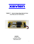
“XCET-1” - Xavien Continuous Event Timer
User Manual and Instructions
XAVIEN
PO Box 7433
Goodyear, Az 85338
www.xavien.com
1
System Overview
The “XCET-1” is a precise 1 second to 31 seconds continuous event timing system used to
control events in a rocket, such as continuously triggering a camera for a user specified time.
Time settings are set using a 6-position DIP switch that eases programming. It runs off of an
external DC power supply ranging from +7V to +15V, a 9V alkaline battery is ideal for powering
the “XCET-1”. Various igniters / electric matches may be used because of the versatility and
design of the “XCET-1”; these include Daveyfire and OXRAL. The “XCET-1” can also be used to
drive a solenoid, servo, relay or some other devices that requires repetitive actions.
Specifications
Battery
PEAK Firing Current
Dimensions
Weight
Nominal Battery Load
Delay Settings
Output Pulse Time
external 7-15 VDC
3A @ 10sec.
0.95” (+/- 0.05”) W x 2.5” (+/- 0.02”) L
14.2 grams
15mA
1 second to 31 seconds (in 1 sec. increments)
0.5 seconds or 1.0 second (user selectable)
Operational Overview
Figure 1 depicts the component layout of the “XCET-1”. The switches are labeled 1 through 6
accordingly. The ON position for the switches is labeled at the top of each DIP switch pack.
Switch 6 is used to set the “ON” time of the output.
Figure 1. “XCET-1” Assembly.
MCU
DIP Switch
XCET-1
WWW.XAVIEN.COM
RED "ARMED" LED
2003
XAVIEN
Igniter / E-Match /
Actuator
Battery Battery +
FS1 FS2
"FAILSAFES"
Figure 2 gives a close look at the DIP switches and explains time value of each switch. Table 1
gives examples of time settings. For example, to get a delay of 10 seconds you would turn ON
switch 2 and switch 4 (2 seconds + 8 seconds = 10 seconds), rest would be OFF. The timing
begins counting down as soon as BOTH failsafes are “OPEN” (disabled). If the unit is powered up
with both failsafes “OPEN”, the unit begins counting down immediately. Make sure fail-safes are
in place BEFORE applying power to the unit. Figure 3A and 3B gives examples of the output
when the switches are setup as depicted. Switch 6 sets the “ON” time of the output. It can be set
to either 0.5s or 1.0s. The output voltage is the same as the input, so if you have the input
powered off of a 9V battery then the output will be 9V. So if you have the “XCET-1” set for 3
seconds with a PULSE time of 1 second and powered off of a 9V battery then the operation will
be as follows:
FS1 and FS2 "OPENED"
(Rocket Launched)
Output = 0V
DELAY for 3 seconds.
OUTPUT = 9V
Delay for 1 second.
2
Figure 2. DIP Switch with all switches in the OFF position.
ON
1
2
3
4
5
6
Switch
Time Value
1
2
3
4
5
6
1 second
2 seconds
4 seconds
8 seconds
16 seconds
PULSE “ON” TIME
** IMPORTANT**: Switches MUST be set prior to turning power on to “XCET-1”.
The MCU ONLY reads the switch settings on power up. If changes need to be
made, turn unit OFF, set switches and cycle power back ON.
Table 1 (Example of delay settings)
Switch Setting
[ 1, 2, 3, 4, 5, 6 ]
Off-Off-Off-Off-Off-Off
On-Off-Off-Off-Off-Off
On-Off-On-Off-Off-Off
Off-On-Off-On-Off-Off
Off-On-On-Off-On-Off
On-On-Off-Off-Off-On
Off-Off-Off-On-Off-On
On-On-On-On-Off-On
Off-Off-On-Off-On-On
On-On-On-On-On-On
Time Delay
Delay = 1 second (default), ON time: 0.5s
Delay = 1 second, ON time: 0.5s
Delay = 5 seconds, ON time: 0.5s (FIG. 3A)
Delay = 10 seconds, ON time: 0.5s
Delay = 22 seconds, ON time: 0.5s
Delay = 3 seconds, ON time: 1s
Delay = 8 seconds, ON time: 1s
Delay = 15 seconds, ON time: 1s
Delay = 20 seconds, ON time: 1s (FIG. 3B)
Delay = 31 seconds, ON time: 1s
Figure 3A.
ON=0.5s
ON
ON=0.5s
ON=0.5s
1 2 3 4 5 6
OFF=5s
OFF=5s
OFF=5s
Figure 3B.
ON=1.0s
ON
ON=1.0s
ON=1.0s
1 2 3 4 5 6
OFF=20s
OFF=20s
OFF=20s
3
“XCET-1” FAILSAFES:
The “XCET-1” has two failsafes to protect against accidental timer countdowns. The failsafes are
“ENABLED” when “FS1” and “FS2” are connected together as in figure 4. The unit will NOT begin
countdown until BOTH failsafes have been “DISABLED” (opened).
Figure 4. FAILSAFES “ENABLED”.
"FAILSAFES"
FS1 FS2
Jumper wires
Once a failsafe has been “DISABLED” (opened), the only way to reset the failsafe is to turn the
power off. Once this is done you can “ENABLE” the failsafe and turn the power back on. We at
XAVIEN have had good luck using “solder” as the jumper wires for the failsafes. Place the length
of solder directly under the engine, when it ignites it will melt the solder and countdown will begin.
Figure 5 shows a basic configuration for using the failsafes for the XAVIEN family of timers.
Figure 5. Basic FAILSAFE configuration
PYROTECHNIC
DEVICES
S-1
S-2
RED LED turns on
when timer is "ARMED"
(FS1 OPEN)
ST-2
ST-1
XAVIEN
"XDSRT-1"
www.xavien.com
"KEY LOCK"
TO ARM / DISARM
TIMER - FS1
Wire loops back where
it can be pulled OPEN
by the rocket after
launch. Wire is 2
pieces that have
exposed copper
twisted together. - FS2
** IMPORTANT**: All connections (FAILSAFE settings and switch
position) must be set BEFORE you apply power to the “XCET-1”.
4
Pyrotechnic / Actuator Installation:
The “XCET-1” can be used as a traditional ignition timer and has been tested using various
igniters and electric matches. To install a pyrotechnic device onto the “XCET-1” you simply
unscrew the terminals located as in figure 5. The terminals are screw based terminal blocks for
easy access and reliability. User does not need to worry about which terminal goes to which leg
of the igniter / electric match. Make sure you hand tighten screw terminals after igniter / electric
match has been installed.
Figure 5A. Pyrotechnic device install location.
Figure 5B. Actuator device install location.
Igniter / Electric
Match
+DC OUTPUT
GROUND
When installing an actuator correct polarity must be observed. The output of the “XCET-1” is the
same voltage that it uses as the input. For example, if you are using a 9V battery, then your
output will be 9V. The “XCET-1” can continuously handle 2 amperes (2A) of current up to 15VDC
or 3A surge at 15VDC for 10 seconds. If you exceed this rating damage to the unit can occur.
Battery Connections:
The “XCET-1” was designed to operate using a 9V alkaline battery. We here at XAVIEN
recommend using a switch (3A MAX CURRENT) to insure ease of use when powering the unit up
and down. We have equipped the unit with a small green power indicator so the user can easily
identify when the unit has power applied. It is recommended that the user do tests using their
igniter / electric match configurations before “assuming” anything will work. This will help to insure
that the “XCET-1” and your configuration will work to your expectations. In figure 6 we have a
basic diagram of the battery connections that are recommended by us. It is always a good idea
to insure you have a fresh (new) battery before any launches occur. After all, the cost of a
battery is nothing compared to the time and money spent on many of our users rockets.
Figure 6. Recommended battery connections.
"XCET-1"
2003
XAVIEN
+
POWER SWITCH
9V ALKALINE
BATTERY
"GREEN" POWER
LED
-
5
Setup Sequence:
This is the recommended sequence for setting up the “XCET-1”.
1. Make sure unit is NOT powered up, if it is turn it OFF,
2. Set DIP switches to desired time delay.
3. Install failsafes, making sure screw terminals are not loose, hand tighten only.
4. Install igniter / electric match or actuator, making sure screw terminals are not loose,
hand tighten only.
5. Install a fresh 9V battery, making sure screw terminals are not loose, hand tighten
only. Reversing the polarity of the battery can damage the “XCET-1”, when installing
the battery refer to figure 1 for the correct polarity.
6. If green LED is ON, turn switch to OFF position if you will not be immediately
launching your rocket. This saves on the life of the battery. When you are ready to
launch, turn switch to ON position, the “XCET-1” is ready to go.
7. When unit is powered up (green LED is ON) verify that the RED “ARMED” LED is off.
If this is on then the rocket is armed and waiting for the second failsafe to be
disabled. This is usually only desired right before the rocket is launched. If the RED
LED is on and this is an undesired state, immediately turn off power to the
“XCET-1” and check your failsafes.
Mounting / Installation
The “XCET-1” must be installed securely to prevent the unit from being damaged during use.
Since this unit does not depend on a “g-switch”, orientation of the unit is very flexible. The
mounting holes are 0.125”; this allows various size screws to be used. Just verify the clearance of
both the screw and the head to insure a proper fit without damaging the unit.
XCET-1
0.5" (12.7mm)
0.475" (12.07mm)
2.05" (52.07mm)
2.5" (63.49mm)
OUTPUT
URGENT: The “XCET-1” MUST be protected from ejection charge and
motor residue. These are corrosive and over time can damage the PCB of
the “XCET-1”. If this occurs, the warranty does not cover this type of
damage.
6
** Handling Precautions **
These units are sensitive to damage from ESD and should always be handled in a properly
grounded environment; damage from ESD is not covered under the warranty. Never transport or
handle a rocket with an “XCET-1” that is powered up and connected to live polytechnic charges.
When installing an “XCET-1” to igniters, make sure unit is powered off. Before cycling power ON
verify that both fail-safes are ARMED to prevent accidental discharge.
!! Product Disclaimer and Limit of Liability !!
Since the use and application of this equipment are beyond our control, the purchaser or user
agrees to hold “XAVIEN” and their agents from any and all legal claims, demands, actions, debts,
liabilities, judgments, costs and attorney fees arising out of, claimed on account of, or in any
manner predicted upon loss or damage to property of, or injuries to or death of, any and all
persons arising out of the use of this equipment. Due to the nature of electronic devices, the
application and environments for these devices, the possibility of failure can never be completely
ruled out. It is the responsibility of the purchaser or user of this equipment to properly test and
simulate the actual conditions under which the device is intended to be used to ensure the
highest degree of reliability, safety and success.
!! Product Warranty !!
The “XCET-1” has a warranty of 1 year starting from date of purchase as long as all the
guidelines have been followed that are outlined is this document. Any improper use or
carelessness on the part of user will void the warranty. If your unit has problems send an email to:
[email protected]
Once this has been done, XAVIEN will send you a return material authorization (RMA) number
that you need to include with your unit. DO NOT send any units back to XAVIEN without this
RMA number, if we receive product with no RMA it will NOT be accepted and mailed back
unrepaired.
Revision History
PCB REV: 1.00A
FW REV: 1.00A
DOC REV: 1.00A
DATE: 09/10/2003
DATE: 09/10/2003
DATE: 09/10/2003
7