1
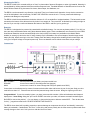
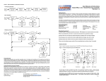
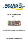
Overview
RRC2+UserManual
Revision1.03
The RRC2+ unit is ready to fly DD (dual deployment) duties as it comes, right out of the box, providing a drogue event at
apogee and a main event at 300 ft AGL. To change any of the altimeter settings, please refer to the Dip Switch Settings
section of this User Manual.
At apogee (highest point of the rocket flight) the RRC2+ will fire a "drogue" charge to separate the rocket airframe (if
drougeless) and/or deploy a small drogue chute to stabilize the airframe components during their free fall. Then at 300 ft. it
will fire a "main" charge to deploy your main parachute.
The RRC2+ is a "barometric" based altimeter -- it needs to sample air to take its readings and function correctly. It must be
solidly mounted in an avionics bay with vent holes in the bay to sample air pressure as the rockets travels up (ascent) and
down (descent).
The RRC2+ will "beep" out continuity before flight, telling you all connections are GO for flight; and upon landing will "beep"
out your max altitude. There is also an LED that blinks in conjunction with the beeps if hearing is a problem. By drilling a hole
in the airframe over the LED you can "SEE" continuity before and "SEE" altitude after flight. Be advised the new RRC2+ is
equipped with a LOW tone beeper for those of us with high-frequency tone loss.
As an improvement over the original RRC2 and RRC2-mini, the RRC2+ has built-in mach immunity. Regardless of how fast
your rocket is flying, you no longer need to be concerned with setting a mach delay. This guarantees no problems during
your flight if you approach or pass through Mach speeds. A full explanation is covered in the RRC3 User Manual.
Other useful things you may want to do with your RRC2+, include:
1. You can use the RRC2+ to deploy just a single parachute at apogee if you’re flying single deployment.
2. Just send it along for the ride to measure altitude, doing NO deployment duties, using motor ejection for deployment.
3. Use it as the main altimeter or as a backup altimeter with any other brand/make altimeter to provide redundant altimeter
recovery.
1 MountingtheRRC2+ The RRC2+ needs to be mounted solidly on a "sled," or plate made of plywood, fiberglass, or other rigid material. Mounting is
accomplished by utilizing standard 4-40 size machine screws and nuts. Insulated Washers or Standoffs can be found on the
Missile Works website or big box stores like Lowes, Home Depot, Ace Hardware, etc.
The RRC2+ can be mounted in any direction on the sled. There is no forward or aft orientation. It may also be mounted on
one of the bulk plates in the avionics bay. DO NOT USE VELCRO to mount the unit. This may cause static discharge
problems and damage to components!
The RRC2+ should be mounted above the sled a minimum of 1/8" on standoffs or insulated washers. The barometric sensor
mounted on the bottom of the altimeter has tiny holes in it to sample air. They must NOT be blocked by mounting too tight on
the sled. If you can slip a credit card between the bottom of the RRC2+ and sled, you’re good to go!
Batteries The RRC2+ is designed to be powered by a standard 9-volt alkaline battery. You can use any battery within 3.7V to 10V, but
there are other considerations when using these alternate battery types. These considerations are covered fully in the RRC3
User Manual. Batteries must be mounted solidly to the sled, usually via a battery box (available on the Missile Works
website) or securely zip tied to the sled. If using a battery clip it is advisable to use several wraps of electrical tape around
battery and clip, before securing it to the sled. Always check the battery voltage before installing & before each flight, and
verify your “beeped” voltage on the pad at power-up! Even new batteries can be defective and have sub-par voltage. Connections
All the RRC2+ terminals are clearly labeled:
BAT+ and BAT Connect power from your battery and power switch here
DROGUE
Low current e-match for first charge that fires (apogee)
MAIN
Low current e-match for second charge that fires (main parachute at 500 ft)
Connections on the altimeter are by means of screw terminals which raise and lower a tiny set of vice jaws. Strip your wire
ends NO more than 1/4". Place the bare wire end into jaws and snug down the screw. Now give a light tug on the wire.
Congratulations! If your wire remains in place, you have just averted the number 1 failure with altimeters and electronic
deployment -- loose wiring. Using the "pull" test on EVERY connection you make, will assure successful and safe flights.
Be SURE to connect the positive [ + ] on your battery to the terminal screw on altimeter marked BAT+ . Then do the same
for the [ - ] negative terminal screw. DO NOT REVERSE THE POLARITY!
The RRC2+ does have built-in polarity protection to prevent damage to components should you "accidentally" connect the
battery in backwards. Carelessness, “Go Fever”, loose wiring and reverse polarity are the most common problems with fliers
causing damage to their units. Take your time and don't be one of them. 2 VentHoles Vent holes in avionics bay allow the altimeter to sample air pressure. Here are typical some 3-hole example sizes:
A. 38 mm by 6 in.
B. 54 mm by 7 in.
C. 3 in. by 9 in.
D. 4 in. by 12 in.
E. 6 in. by 18 in.
3 x 1/16” holes
3 x 1/8" holes
3 x 5/32” holes
3 x 3/16” holes
3 x 1/4"holes
Make sure when drilling holes they are clean and clear from fuzz and debris for smooth, clear airflow. Locate your vent holes
equally spaced around the avionics bay in a single circumference. If you want more information about proper venting sizes,
refer to the RRC3 User Manual section on Static Pressure Ports
DIPSwitchSettings
Switch
1
2
3
4
OFFPositionSetting
ONPositionSetting
BeeperoperatesatLOWTONE(1KHz)
DrogueEventfiresatApogee
Maineventfiresat300’AGL
Adds0ft.toMain(Main=300’or800’)
BeeperoperatesatHIGHTONE(2.5KHz)
DrogueEventfiresatApogee+1second
Maineventfiresat800’AGL
Adds200ft.toMain(Main=500’or1000’)
Switch 1 allows you to set a high or low beeper tone (useful when flying multiple units to aid in distinguishing beeps).
Switch 2 lets you set the RRC2 to operate in a backup role, activating its drogue event at 1 second after apogee.
Switches 3 & 4 let you set the elevation for your main parachute event (300’, 500’, 800’, or 1000’ AGL).
The DIP switches are read by the altimeter at power up only. Always preset the altimeter before arming your unit. ReadingtheBeeps/Blinks When you first power up the RRC2+, it will beep for 1 second. After a short pause, the RRC2+ will beep the last altitude
flown on its previous flight. Next the altimeter will beep battery voltage (volts, then 1/10th volts). The RRC2+ then goes
through the POST (Power On Self Test). If a fault is detected during the POST, the RRC2+ will beep out a fault code (see
the POST Mode Section), otherwise it beeps continuity readiness pre-launch and after landing will beep out the altitude.
On the pad, with your ejection charges connected to the drogue and main terminals you will have the following beeps/blinks
for continuity (everything is hooked up correct and GO for flight) every 5 seconds:
Drogue only
Main only
Drogue and Main
No charges
1 beep repeating every 5 seconds
2 beeps repeating every 5 seconds
3 beeps repeating every 5 seconds (for Dual Deploy)
1 Long beep (ride along only, and nothing hooked up)
After 5 minutes of beeping continuity, the RRC2+ will switch into power saving mode, conserving your battery for
flight operations. You will hear 1 short beep every 15 seconds during power saving mode as it waits for launch.
After flight and upon landing, the RRC2+ will beep/blink your maximum altitude (Example: 2650 ft.):
2 beep-beep [pause]
6 beep-beep-beep-beep-beep-beep [pause]
5 beep-beep-beep-beep-beep [pause] 0 long‐beep [pause] low buzz [long pause / beeping complete] (NOTE: The RRC2+ repeats this sequence until you turn power off). EjectionChargesandE‐matches The RRC2+ is designed to be used with low-current electric matches. These include Daveyfire, Oxral, MTEK, JTEK, or low
current motor igniters like the Quest Q2G2. Another common mistake made with altimeters and electronic deployment is
crossing up the drogue and main connections. Always double check your wiring to verify the drogue and main connections. 3 FinalAssemblyTesting Once you’ve got your ejection charges connected to the altimeter and your av-bay is assembled, it’s always a wise idea to
“pre-test” for continuity and avoid any surprises on the pad when the rocket is assembled and launch ready. Be sure that
prior to performing this test that you’re safely clear of people, vehicles, or other flammable materials. Safety glasses and
other personal protection are also recommended. Be sure the charges are facing away from you and others, and then power
up the altimeter to assure everything is operating as you intend.
Specifications
Microcontroller
Pressure/Temperature sensor
Operational Range
Arming Mode
Battery Voltage
Continuity Current (@t 9V)
Firing Current (@ 9v)
16MHz 16-bit MSP430 Series mCU
MSI MS5607 Pressure sensor with 24 bit ∆Σ ADC
40K MSL recommend (100K MSL capable)
Barometric / 200’ AGL
3.5 volts to 10 volts
50 µa
5 amps for 1 second (Drogue / Main)
POSTModeFaultCodes
Codes are preceded by a very distinct warning tone (7 very quick low beeps), followed by the beeping/flashing of the fault.
DO NOT FLY THE RRC2+ until the fault or warning is resolved and corrected.
Code
1
2
3
4
5
6
Fault
Ambient Barometric Fault / Unstable conditions during Launch Commit Test
Barometric sensor Fault / No communication reply
Barometric sensor Fault / Prom CRC Mismatch
Barometric pressure Fault / Pressure < 10 mbar or > 1200 mbar
Temperature Fault / Temperature < -40 deg. C or > 85 deg. C
I/O Line Fault
HandlingPrecautions
- Always handle the RRC2+ in a static-free, grounded environment
- Never touch/handle the RRC2+ when it is armed and connected to live pyrotechnic charges
- Always allow the RRC2+ to adjust to ambient temperature conditions prior to arming and flying
- Always prepare your rocket and recovery system components with the RRC2+ powered off
- Never cycle the RRC2+ power switch off, then immediately back on (allow at least 10 seconds).
ProductWarranty Missile Works Corporation has exercised reasonable care in the design and manufacture of this product and warrants the
original purchaser that the RRC2+ is free of defects and that it will operate at a satisfactory level of performance for a period
of one year from the original date of purchase. If the system fails to operate as specified, then return the unit (or units) within
the warranty period for repair or replacement (at our discretion). The system must be returned by the original purchaser, and
be free of modification or any other physical damage which renders the system inoperable. Upon repair of replacement of
the unit, Missile Works Corporation will return the unit postage-paid to the original purchaser. ProductDisclaimerandLimitofLiability Because the use and application of this equipment are beyond our control, the purchaser or user agrees to hold harmless
Missile Works Corporation and their agents from any and all claims, demands, actions, debts, liabilities, judgments, costs,
and attorney fees arising out of, claimed on account of, or in any manner predicated upon loss or damage to property of, or
injuries to or the death of any and all persons arising out of the use this equipment. Due to the nature of electronic devices,
and the application and environments for those devices, the possibility of failure can never be totally ruled out. It is the
responsibility of the purchaser or user of this equipment to properly test and simulate the actual conditions under which the
device is intended to be used to ensure the highest degree of reliability and success.
Copyright © 2013 by Missile Works Corporation
PO Box 1725 Lyons CO 80540 303.823.9222 www.missileworks.com 4