1
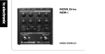
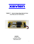
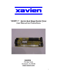
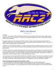
“XCIC-1” - Xavien Cluster Ignition Controller
User Manual and Instructions
XAVIEN
PO Box 7433
Goodyear, Az 85338
www.xavien.com
1
System Overview
The “XCIC-1” is a G-SWITCH activated cluster igniter. This unit was designed for people wanting
to make air starting of motor clusters easier, more reliable and economical. The “XCIC-1” uses
high current FET technology to enable the ignition of multiple pyrotechnic devices. The GSWITCH activates the igniters / electric matches when it senses 2.1Gs (+/-10%) of force. The
device was designed to operate with a 9V battery.
Specifications
Battery
PEAK Firing Current
Dimensions
Nominal Battery Load
external 7-15 VDC
10A @ 3sec.
0.95” (+/- 0.05”) W x 1.25” (+/- 0.02”) L
10mA
Operational Overview
Figure 1 depicts the component layout of the “XCIC-1”. The “XCIC-1” activates the igniters based
on a G-SWITCH closing after rocket has accelerated to 2.1Gs (+/-10%). The unit has a GREEN
“POWER” LED as well as a RED “CONTINUITY” LED. The unit must be oriented in such a way
that the direction of travel matches the arrow on the “XCIC-1” PCB.
Figure 1. “XCIC-1” Assembly.
IGNITER / E-MATCH /
PYRO OUTPUT
Direction of Travel
<-XCIC-1
www.xavien.com
+
GREEN
"POWER"
LED
9V BATTERY (+)
RED
"CONTINUITY"
LED
9V BATTERY (-)
** IMPORTANT**: Unit MUST be powered OFF when
installing igniter / electric match and “XCIC-1” into rocket.
ONLY turn power ON after “XCIC-1” is installed, the rocket
is setup on the launch pad and you are ready to launch the
rocket. Sudden movement (“jerking motion”) can cause
unit to activate. NEVER transport your rocket with an
“XCIC-1” that is installed and powered up!
2
Connections:
The “XCIC-1” was designed to operate using a 9V alkaline battery. We have equipped the unit
with a small green “POWER” indicator so the user can easily identify when the unit has power
applied. The “XCIC-1” also has a red “CONTINUITY” LED to indicate igniter / electric match
continuity. When using a bunch of igniters in parallel remember that if 1 of them has continuity
then the LED will turn ON. It is recommended that the user do tests using their igniter / electric
match configurations before “assuming” anything will work. This will help to insure that the “XCIC1” and your configuration will work to your expectations. In figure 2 we have a basic diagram of
the battery and igniter / electric match connection that are recommended by us. It is always a
good idea to insure you have a fresh (new) battery before any launches occur. After all, the
cost of a battery is nothing compared to the time and money spent on many of our users
rockets.
Figure 2. Recommended battery connections.
RED
"CONTINUITY"
LED
PYRO(s)
XCIC-1
<--
+
+
POWER SWITCH
GREEN
"POWER"
LED
9V ALKALINE
BATTERY
www.xavien.com
Figure 3. Recommended pyro connections.
IGNITERS / E-MATCHES
IN PARALLEL
<-XCIC-1
www.xavien.com
Figure 3 shows the recommended configuration when using
multiple igniters / e-matches. The “XCIC-1” has been tested using
OXRAL and DAVEYFIRE products, it is recommended that you
test your configuration before launching the rocket. This will ensure
that your particular configuration will operate correctly and
decrease your chances of having a ignition problem.
+
3
Setup Sequence:
This is the recommended sequence for setting up the “XCIC-1”.
1. Make sure unit is NOT powered up, if it is turn it OFF,
2. Install igniter / electric match, making sure screw terminals are not loose, hand
tighten only.
3. Install a fresh 9V battery, making sure screw terminals are not loose, hand tighten
only. Reversing the polarity of the battery can damage the “XCIC-1”, when installing
the battery refer to figure 1 for the correct polarity.
4. Turn POWER ON, if green LED is ON, then POWER is being supplied to the unit. If
you have an igniter / electric match connected, the RED “CONTINUITY” LED should
be ON. If not there may be a problem with the igniters. If the unit has both the RED
and GREEN LEDs ON, turn the unit OFF if you are not ready to launch the rocket.
This saves on the life of the battery. When you are ready to launch, turn switch to ON
position, the “XCIC-1” is ready to go.
“XCIC-1” Configuration Testing:
This is the recommended sequence for testing the “XCIC-1” to verify your pyro configuration.
1. Setup unit per the “SETUP SEQUENCE” as listed above.
2. Short (using a piece of wire) the two leads of the G-SWITCH, this will “simulate” the
G-SWITCH being closed and activate the pyros. See FIGURE 4 for wire placement.
Use caution when performing this test, you will be activating whatever pyros
(igniters / e-matches) that are connected to the “XCIC-1”.
Figure 4. Test wire placement.
Jumper Wire
PYRO(s)
XCIC-1
<--
+
www.xavien.com
4
Mounting / Installation
The “XCIC-1” must be installed securely to prevent the unit from being damaged during use.
Since this unit depends on a “G-SWITCH”, orientation of the unit needs to be mounted so
the arrow on the PCB matches with the rockets direction of travel. The mounting holes are
0.125”; this allows various size screws to be used. Just verify the clearance of both the screw and
the head to insure a proper fit without damaging the unit.
XCIC-1
1.025" (26.03mm)
0.7" (17.77mm)
URGENT: The “XCIC-1” MUST be protected from ejection charge and
motor residue. These are corrosive and over time can damage the PCB of
the “XCIC-1”. If this occurs, the warranty does not cover this type of
damage.
5
** Handling Precautions **
These units are sensitive to damage from ESD and should always be handled in a properly
grounded environment; damage from ESD is not covered under the warranty. Never transport or
handle a rocket with an “XCIC-1” that is powered up and connected to live polytechnic charges.
When installing an “XCIC-1” to igniters, make sure unit is powered off.
!! Product Disclaimer and Limit of Liability !!
Since the use and application of this equipment are beyond our control, the purchaser or user
agrees to hold “XAVIEN” and their agents from any and all legal claims, demands, actions, debts,
liabilities, judgments, costs and attorney fees arising out of, claimed on account of, or in any
manner predicted upon loss or damage to property of, or injuries to or death of, any and all
persons arising out of the use of this equipment. Due to the nature of electronic devices, the
application and environments for these devices, the possibility of failure can never be completely
ruled out. It is the responsibility of the purchaser or user of this equipment to properly test and
simulate the actual conditions under which the device is intended to be used to ensure the
highest degree of reliability, safety and success.
!! Product Warranty !!
The “XCIC-1” has a warranty of 1 year starting from date of purchase as long as all the guidelines
have been followed that are outlined is this document. Any improper use or carelessness on the
part of user will void the warranty. If your unit has problems send an email to:
[email protected]
Once this has been done, XAVIEN will send you a return material authorization (RMA) number
that you need to include with your unit. DO NOT send any units back to XAVIEN without this
RMA number, if we receive product with no RMA it will NOT be accepted and mailed back
unrepaired.
Revision History
PCB REV: 1.00A
DOC REV: 1.01A
DATE: 11/18/2003
DATE: 08/09/2005 [UPDATED LOGO]
6