1
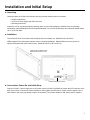
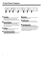
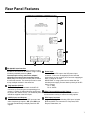
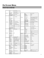
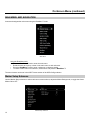
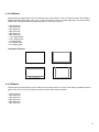
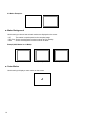
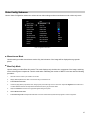
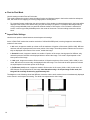
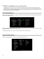
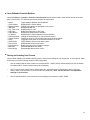
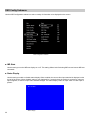
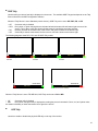
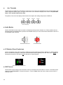
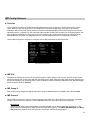
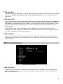
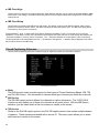
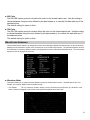
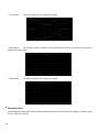
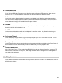
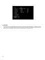
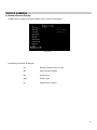
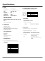
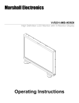
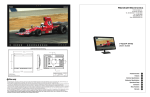
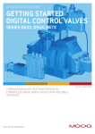
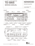
Marshall Electronics
Model No.
V-R261-DLW
26" Full Resolution Dual Link / Waveform Monitor
Operating Instructions
This page intentionally left blank
2
Contents
Features............................................................................................................................................................4
Installation and Initial Setup .......................................................................................................................5
Unpacking .......................................................................................................................................................................................................................................................5
Installation ......................................................................................................................................................................................................................................................5
Connections and Power-On..........................................................................................................................................................................................................................5
Front Panel Features.....................................................................................................................................6
Power Button..................................................................................................................................................................................................................................................6
Input Channel Buttons ..................................................................................................................................................................................................................................6
DVI Button.......................................................................................................................................................................................................................................................6
User-Definable Function Buttons.................................................................................................................................................................................................................6
Layout Button.................................................................................................................................................................................................................................................6
RotoMenu™ Knob..........................................................................................................................................................................................................................................6
Image Adjustment Knobs..............................................................................................................................................................................................................................6
Rear Panel Features ......................................................................................................................................7
RS-422/485 Serial Interface ...........................................................................................................................................................................................................................7
Tally Interface .................................................................................................................................................................................................................................................7
3G-SDI Inputs and Outputs ...........................................................................................................................................................................................................................7
Power Input.....................................................................................................................................................................................................................................................7
VESA 75mm and 200 mmHole Pattern ........................................................................................................................................................................................................7
DVI-I Input Connector ...................................................................................................................................................................................................................................7
Compatible Input Formats ...........................................................................................................................8
DLW Monitor Layouts ...................................................................................................................................9
On-Screen Menu...........................................................................................................................................11
STRUCTURE OVERVIEW ............................................................................................................................................................................................................................11
MAIN MENU AND NAVIGATION..................................................................................................................................................................................................................12
Marker Setup Submenu...............................................................................................................................................................................................................................12
16:9 Markers ...........................................................................................................................................................................................................................................13
4:3 Markers .............................................................................................................................................................................................................................................13
Marker Background ...............................................................................................................................................................................................................................14
Center Marker.........................................................................................................................................................................................................................................14
Video Config Submenu ...............................................................................................................................................................................................................................15
Monochrome Mode ................................................................................................................................................................................................................................15
Blue-Only Mode......................................................................................................................................................................................................................................15
Pixel-to-Pixel Mode................................................................................................................................................................................................................................16
Aspect Ratio Settings............................................................................................................................................................................................................................16
Curtain Color ..........................................................................................................................................................................................................................................17
Ctemp/Gamma........................................................................................................................................................................................................................................17
Analog Phase .........................................................................................................................................................................................................................................17
DVI-A CSC Mode ....................................................................................................................................................................................................................................17
DVI-D CSC Mode ....................................................................................................................................................................................................................................17
HDMI CSC Auto ......................................................................................................................................................................................................................................18
Color Configuration Submenu ...................................................................................................................................................................................................................18
System Configuration Submenu ................................................................................................................................................................................................................18
User-Definable Function Buttons ........................................................................................................................................................................................................19
Saving and Loading User Presets .......................................................................................................................................................................................................19
OSD Configuration Submenu .....................................................................................................................................................................................................................20
IMD State.................................................................................................................................................................................................................................................20
Status Display ........................................................................................................................................................................................................................................20
OSD Tally ................................................................................................................................................................................................................................................21
LED Tally.................................................................................................................................................................................................................................................21
Ancillary Timecode................................................................................................................................................................................................................................22
Audio Monitor.........................................................................................................................................................................................................................................22
CC Monitor..............................................................................................................................................................................................................................................22
OSD Timeout ..........................................................................................................................................................................................................................................22
IMD Configuration Submenu ......................................................................................................................................................................................................................23
Overview .................................................................................................................................................................................................................................................23
IMD ID# ....................................................................................................................................................................................................................................................23
IMD Group #............................................................................................................................................................................................................................................23
IMD Protocol...........................................................................................................................................................................................................................................23
Tally Source............................................................................................................................................................................................................................................24
IMD Baud Rate........................................................................................................................................................................................................................................25
IMD Name (S/N) ......................................................................................................................................................................................................................................25
IMD Tally Mode.......................................................................................................................................................................................................................................25
IMD Fixed Configuration Submenu............................................................................................................................................................................................................25
IMD Fixed Color......................................................................................................................................................................................................................................25
IMD Fixed Align ......................................................................................................................................................................................................................................26
IMD Fixed String.....................................................................................................................................................................................................................................26
Closed Captioning Submenu......................................................................................................................................................................................................................26
Wave/Vector Submenu ................................................................................................................................................................................................................................27
Ancillary Submenu.......................................................................................................................................................................................................................................29
DID/SDID .................................................................................................................................................................................................................................................30
SERVICE SUBMENU ....................................................................................................................................................................................................................................31
Software Version Display......................................................................................................................................................................................................................31
Specifications ...............................................................................................................................................32
Maintenance ..................................................................................................................................................34
Warranty .........................................................................................................................................................34
3
Features
The V-R261-DLW (Dual Link / Waveform) monitor is the latest addition to Marshall's expanding line of IMD-equipped
monitors.
■ 1920 x 1200 Full Resolution 26” Panel
The V-R261-DLW features an all-digital TFTMegaPixel active matrix LCD system with 1920x1200
native resolution. The LCD panel features a
2
brightness of 500 cd/m and a 800:1 contrast ratio
making it ideal in a variety of environments and
lighting conditions.
■ Multi mode, Vectorscope and Waveform Monitor
mode
The DLW monitor series includes a real-time
Waveform monitor and Vectorscope along with
support for SDI, HD-SDI, 3G-SDI and Dual Link SDI.
With the monitor in Multi mode, the monitor will break
into four quadrants and display Signal Input
information (Link Status), Embedded Audio levels, a
Waveform monitor, a Vectorscope and live video
simultaneously. Additional layouts provide the ability
to view the Waveform monitor, Vectorscope, SDI Link
status and Video individually.
■ Closed Captioning Decoding
The DLW monitor allows for decoding of Closed
Captioning in the EIA-608 or EIA-708.
4
■ In-Monitor Display
In-Monitor Display allows on-screen text and tally
indication, controlled locally or remotely via a variety
of industry standard protocols.
■ OSD Features (On Screen Display)
Embedded time code and an embedded audio
presence indicator can be displayed on the screen in
a variety of configurations. Closed Caption presence
indication is also provided for 608/708 captions.
■ Advanced Features
Color temperature adjustment, aspect ratio settings,
blue-only mode, and monochrome mode are a few of
the advanced features allowing the V-R261-DLW to
be at home in any broadcast environment. Pixel-toPixel mode also allows native display of any incoming
image format.
■ Four User-Definable Function Buttons
Four user-definable function buttons allow quick
access to numerous settings and features including
aspect ratio, monochrome mode, color temperature,
and more.
Installation and Initial Setup
■ Unpacking
Carefully unpack the V-R261-DLW monitor and verify that the following items are included:
• V-R261-DLW Monitor
• V-PS24-7.5 Power Supply with XLR Connector
• Operating Instructions
Inspect the unit for any physical damage that may have occurred during shipping. Should there be any damage,
immediately contact Marshall Electronics at (800) 800-6608. If you are not located within the continental United States,
call +1 (310) 333-0606.
■ Installation
The V-R261-DLW can be combined with a desktop stand for desktop use. (Marshall Part V-ST23-32).
VESA standard 75mm hole patterns allows custom mounting installations. Marshall Electronics can provide an
optional VESA stand with pivot and tilt as well. (Marshall Part VP-LCD171H-ST-01).
V-R261-DLW with desktop stand
(Marshall Part Number V-ST2332)
Desktop Stand Mounting Holes
■ Connections, Power-On and Initial Setup
Plug the V-PS24-7.5 power supply into an AC power source (100-240 V @ 50/60 Hz). Attach the XLR connector to the
back of the monitor. Connect the required cables for video signals input and output. (Power must be applied to the VR261-DLW for the active loop-though output to be activated.) The monitor defaults to ‘ON’ when power is supplied.
5
Front Panel Features
Power Button
Turn the monitor off or on by pressing the power
button. The LED on the power button is at
maximum illumination when the unit is OFF. The
LED is at minimum illumination when the unit is on.
Input Channel Buttons
Pressing SDI 1 or SDI 2 will select HDSDI-SDI Video
Inputs 1 or 2, respectively. When a channel is
activated, the LED on the channel will illuminate.
When displaying Dual Link formats, both LEDs will
illuminate simultaneously.
DVI Button
Pressing the DVI button selects the DVI-I input.
When activated, the LED will light.
User-Definable Function Buttons
Four user-definable function buttons can be used for
direct access to various settings. Functions are
assigned using the on-screen menu.
6
Layout Button
Use this button to switch between the four available
layouts on the V-R261-DLW.
RotoMenu™ Knob
The RotoMenu™ knob allows for accessing and
navigating the main menu, using only a single control.
Image Adjustment Knobs
Use the image adjustment knobs to adjust color
saturation, brightness and contrast of the image. The
status of each image adjustment parameter is shown on
the top left of the screen, with values ranging from 0 to
100. Pressing a knob once displays the current value.
Pressing a knob twice resets the corresponding
adjustment to the default setting.
Rear Panel Features
RS-422/485 Serial Interface
The RS-422/485 ports are used to remotely control
the IMD or all V-R261-DLW features, using a variety
of industry standard protocols. (Note:
Connector/pin-out may need to be adapted
depending on protocol and controlling device
used.) Only one connection to either port is needed
to control the monitor. The second port can be used
to loop multiple monitors in the same bus.
Tally Interface (HD-15)
THE OSD Tally can be activated via the HD-15
connector by connecting the corresponding pin to
ground. A variety of external devices can be used
to perform the contact closure. No additional power
should be supplied ot the HD-15 port.
3G-SDI Inputs and Outputs
The V-R261-DLW has two 3G-SDI inputs and two
active loop-through outputs. SDI 1 and SDI 2 can
be used simultaneously to display Dual Link SDI
signals.
Power Input
Connect the 24 VDC input to the XLR power input
connector. Power can be supplied from the included
power supply or from a variety of DC sources supplying at
least 7.5 Amps at 24 Volts.
IMPORTANT: If using a power source other than the
included power supply, be sure that the polarity of the DC
input is correct:
Pin 1: GND
Pin 4: 24VDC
VESA 75mm and 200 mm Hole Pattern
VESA-standard 75 mm hole-patterns are provided to
accommodate a variety of custom mounting options.
DVI-I Input Connector
Integrated DVI Digital and Analog VGA input. Includes
EDID and HDCP for connection to Computers, DVD
Players, Rasterizers, etc.
7
Compatible Input Formats
The following SDI standards are supported by the V-R261-DLW:
525i, 625i
1035i (60 / 59.94)
1080i (60 / 59.94 / 50)
1080psF (24 / 23.98)
1080p (23.98 / 24 / 25 / 29.97 / 30)
720p (60 / 59.94 / 50)
720p (23.98 / 24 / 25 / 29.97 / 30)
The following 3G-SDI standards are supported by the V-R261-DLW:
YCbCr (4:2:2) 10 Bit - Level A / B
1080p (60 / 59.94 / 50)
YCbCr/RGB (4:4:4 / 4:2:2) 10 Bit / 12 Bit - Level A / B
1080i (60 / 59.94 / 50)
1080p (30 / 29.97/ 25 / 24 / 23.98)
1080psF (30 / 29.97 / 25 / 24 / 23.98)
YCbCr+A/RGB+A (4:4:4:4) 10 Bit / 12 Bit - Level A / B
1080i (60 / 59.94 / 50)
1080p (30 / 29.97/ 25 / 24 / 23.98)
1080psF (30 / 29.97 / 25 / 24 / 23.98)
The following Dual Link standards are supported by the V-R261-DLW:
YCbCr (4:2:2)
1080p (60 / 59.94 / 50)
YCbCr/RGB (4:4:4 / 4:2:2) 10 Bit / 12 Bit
1080i (60 / 59.94 / 50)
1080p (30 / 29.97/ 25 / 24 / 23.98)
1080psF (24 / 23.98)
YCbCr+A/RGB+A (4:4:4:4 ) 10 Bit / 12 Bit
1080i (60 / 59.94 / 50)
1080p (30 / 29.97/ 25 / 24 / 23.98)
1080psF (24 / 23.98)
Dual Link
2k p(23.98 / 24 / 25 / 29.97 / 30)
The following VESA standards are supported by the V-R261-DLW (DVI-I input):
640x480 @60Hz
800x600 @60Hz
1024x768 @60Hz
1280x1024 @60Hz
1600x1200 @60Hz
The following DVI-Video standards are supported by the V-R261-DLW (DVI input):
1080p/60, 1080p/59.94, 1080p/50
1080i/60, 1080i/59.94, 1080i/50
1080p/23.98, 1080p/24, 1080p/25, 1080p/29.97, 1080p/30
720p/60, 720p/59.94, 720p/50
8
DLW Monitor Layouts
The V-R261-DLW has 4 possible layouts, Multi mode, Vectorscope mode, Waveform mode and Full Screen Video
mode. Each press of the LAYOUT Button will change the current mode to next available mode.
Default Multi mode Layout
Vectorscope Mode
9
Waveform Monitor Mode
Full Screen Video Mode
10
On-Screen Menu
STRUCTURE OVERVIEW
11
On-Screen Menu (continued)
MAIN MENU AND NAVIGATION
Access and navigate the main menu using the RotoMenu™ knob:
Main Menu
Using the RotoMenu knob
• Press the RotoMenu™ knob to enter the main menu.
• Rotate the knob to scroll up or down in the main menu or each submenu.
• Press the RotoMenu™ knob to enter a submenu or choose a setting.
• To return to main menu from submenu, select ‘Back’ and press the RotoMenu™.
The menu timeout can be set in the OSD Timeout section of the OSD Config submenu.
Marker Setup Submenu
Use the Marker Setup submenu to select various on-screen markers, adjust the Marker Background, or toggle the Center
Marker ON or OFF.
Marker Setup Submenu
12
■ 16:9 Markers
Use this setting to superimpose one of 10 markers on the screen when in 16:9 or Full Screen mode. This setting is
disabled when the aspect ratio is set to 4:3, or when Pixel-to-Pixel mode is enabled. Note that in Full Screen mode,
markers are vertically stretched along with the picture to fit the 16:10 screen.
•
•
•
•
•
•
•
•
•
•
•
Off (No Marker)
95% Safe Area
93% Safe Area
90% Safe Area
88% Safe Area
80% Safe Area
1.85:1 Aspect Ratio
2.35:1 Aspect Ratio
4:3 Aspect Ratio
14:9 Aspect Ratio
13:9 Aspect Ratio
16:9 Marker Examples:
OFF (No Marker)
90% Safe Area
2.35:1 Aspect Ratio
4:3 Aspect Ratio Marker
■ 4:3 Markers
Use this setting to superimpose one of 5 markers on the screen when in 4:3 mode. This setting is disabled when the
aspect ratio is set to 16:9 or Full Screen, and when Pixel-to-Pixel mode is enabled.
•
•
•
•
•
•
Off (No Marker)
95% Safe Area
93% Safe Area
90% Safe Area
88% Safe Area
80% Safe Area
13
4:3 Marker Examples:
OFF (No Marker)
90% Safe Area
■ Marker Background
Use this setting to choose how selected markers are displayed on the screen:
• Off
The marker is superimposed on the complete image.
• 50% Gray Screen area beyond the marker is shown at 50% intensity.
• Black
Screen area beyond the marker is shown as black.
Example (80% Marker in 4:3 Mode):
Background OFF
50% Gray Background
■ Center Marker
Use this setting to display a center marker on the screen.
Center Marker
14
Black Background
Video Config Submenu
Use the Video Configuration submenu to select various video settings such as monochrome mode or blue-only mode.
Video Configuration Submenu
■ Monochrome Mode
Use this setting to enable monochrome mode. Only the luminance of the image will be displayed as a grayscale
picture.
■ Blue-Only Mode
Use this setting to enable Blue-Only mode. This mode displays only the blue color component of the image, switching
off the red and green components. Use this mode when calibrating the monitor to SMPTE color bars with the following
procedure:
1.
Allow the monitor to warm up for at least 5-10 minutes.
2.
Display SMPTE split-field color bars on the monitor using an external source.
3.
Enable Monochrome mode.
4.
Locate the pluge pattern (super black, black, and gray bars) at the lower-right corner of the screen. Adjust the Brightness knob until there is
no visible difference between the super black and black bars, but the gray bar is still visible.
5.
Adjust the Contrast knob until an even grayscale appears along the top bars.
6.
Disable Monochrome mode.
7.
Enable Blue-Only mode and adjust the Color knob so that the outermost bars (white and blue) appear to match in brightness.
15
■ Pixel-to-Pixel Mode
Use this setting to enable Pixel-to-Pixel mode.
This mode bypasses the monitor’s internal scaling function and displays images in their native resolution and aspect
ratio, with a one-to-one mapping of incoming image pixels to screen pixels:
•
For incoming formats smaller than the native resolution of the window (or selected aspect ratio), the image will be
displayed in the center of the window using only the necessary LCD pixels. For example, 480i images will only
occupy exactly 640x480 pixels in a particular channel window in DLW mode, or if the channel is selected full
screen, it will occupy exactly 640x480 pixels in the center of the screen. The surrounding screen area will be
black.
■ Aspect Ratio Settings
Use this menu option to switch between several aspect ratio settings.
As the V-R261-DLW monitor has a native resolution of 1920x1200 RGB pixels, incoming images are automatically
scaled to fit the screen:
•
In 4:3 mode, images are scaled up or down to fill the maximum 4:3 portion of the screen (1600 x 1200). IMD text
and time code are superimposed on the lower portion of the image. The audio presence indicator and on-screen
tally are displayed at the bottom of the screen, outside the image.
•
In Scaled 4:3 mode, images are scaled to a smaller 4:3 portion of the screen, leaving space for IMD text, tally,
and audio presence indicator to be displayed below or around the image. Time code is superimposed on the
lower portion of the image.
•
In 16:9 mode, images are scaled to fill the maximum 16:9 portion at the top of the screen (1920 x 1080). In this
mode, IMD text and on-screen tally are displayed below the image. Time code and the audio presence indicator
are superimposed on the lower portion of the image.
•
In Full Screen (16:10) mode, images are scaled to fill the entire 16:10 screen (1920 x 1200). In this mode, all
OSD features are superimposed on the image. Note that when using a 16:9 input image in this mode, the
image will be vertically stretched by approximately 10%.
The diagrams on the following show how IMD text, timecode, and the audio monitor icon are simultaneously displayed
on the screen in each aspect ratio setting. The white area represents the video image.
16
■ Curtain Color
Use this setting to choose the default color displayed on the screen when no video input is present. Available colors
are blue, red, green, white, and black.
■ Ctemp/Gamma
Use this setting to choose one of three color temperature / gamma presets or to remove gamma settings:
•
•
•
•
Linear (No gamma applied)
55K
65K
93K
■ Analog Phase (DVI-Analog or VGA input only)
Adjusts the analog phase value to improve picture quality on DVI-A or VGA Sources. This adjusts the signal phase
(not color phase) of the analog-to-digital conversion.
• 0-31 (value)
■ DVI-A CSC Mode (DVI-Analog input only)
Use the DVI-A CSC Mode to accommodate for four different types of colorspace inputs. This setting will only affect
your DVI-A inputs.
•
•
•
•
RGB Studio: accommodates digital 480i video using the RGB limited range (16-235) inputs.
RGB PC: accommodates full range RGB (0-255) inputs.
YUV 601: accommodates for Rec. 601 SDTV YUV colorspace inputs.
YUV 709: accommodates for Rec. 709 HDTV YUV colorspace inputs.
The monitor’s default setting is RGB PC.
■ DVI-D CSC Mode (DVI-D input only)
Use the DVI-D CSC Mode to accommodate for four different types of colorspace inputs. This setting will only affect
your DVI-D and HDMI inputs.
•
•
•
•
RGB Studio: accommodates digital 480i video using the RGB limited range (16-235) inputs.
RGB PC: accommodates full range RGB (0-255) inputs.
YUV 601: accommodates for Rec. 601 SDTV YUV colorspace inputs.
YUV 709: accommodates for Rec. 709 HDTV YUV colorspace inputs.
The monitor’s default setting is RGB PC.
17
■ HDMI CSC Auto (HDMI input only, via the DVI-I interface)
The HDMI CSC Auto setting is used to accommodate newer HDMI interfaces that send colorspace signaling in the
HDMI data stream. If this setting is set to On, the monitor will automatically determine which colorspace setting to use.
If this setting is set to Off, or your HDMI signal does not contain colorspace signaling, the DVI-D CSC Mode described
above will determine the colorspace configuration.
Color Config Submenu
Use the Color Configuration submenu to adjust the Red, Green and Blue Offset and Gain values of the two SDI channels,
the DVI-D input and DVI-A input.
Each column adjusts a particular input channel, from SDI1 and SDI2 to the DVI-I input. For the DVI-I input, you can adjust
the Offset and Gain for either a DVI-D or DVI-A input.
The Reset option allows you to return to the default settings for each individual channel.
System Config Submenu
Use the System Configuration submenu to control various system parameters.
System Configuration Submenu
18
■ User-Definable Function Buttons
Use the Function 1, Function 2, Function 3 and Function 4 menu items to define each function button on the front
panel of the monitor. The following options are available for each button:
•
•
•
•
•
•
•
•
•
•
•
•
•
•
•
•
Marker
Center Marker
Marker Backgrd
IMD State
Anc. Time Code
OSD Tally
Audio Monitor
CC Monitor
Waveform Mode
Overlay Position
Limits
Aspect Ratio
Pixel to Pixel
Ctemp/Gamma
Blue Only
Monochrome
Toggle between different Screen Markers
Display/hide the Center Marker
Change how markers are displayed on the screen
Display/hide IMD text
Display/hide time code
Rotate amongst types of OSD Tally
Display/hide audio presence indicator
Display/hide the Closed Caption Presence indicator
Change the data displayed on the Waveform monitor
Change the position of the WFM Overlay in DLW Overlay Mode
Toggle the Limits option of the Waveform Monitor On or Off
Toggle between 4:3 and 16:9 aspect ratios
Enable/disable Pixel-to-Pixel mode
Rotate amongst color temperature settings
Enable/disable Blue Only mode
Enable/disable Monochrome mode
■ Saving and Loading User Presets
Use the SAVE CONFIG and LOAD CONFIG menus to save current settings to one of 6 presets, or load a preset. Each
Preset saves all monitor settings except for IMD configuration.
•
Use the LOAD CONFIG menu to load one of presets USR1 – USR6. Factory default settings can also be loaded
by selecting MFG. (Factory defaults cannot be overwritten.)
•
Use To perform a full system restore, which resets ALL adjustable fields on the monitor to their “fresh-fromfactory” state, press the Power, F1 and F2 button simultaneously. Note: You will lose ALL user adjustable
settings on your monitor.
•
Use the SAVE CONFIG menu to save the current settings to a preset from USR1- USR6.
19
OSD Config Submenu
Use the OSD Configuration submenu to select a variety of information to be displayed on the screen.
OSD Configuration Submenu
■ IMD State
Use this setting to turn the IMD text display on or off. This setting affects both fixed string IMD text and remote IMD text
commands.
■ Status Display
Use this setting to enable or disable status display. When enabled, the current video input standard is displayed on the
top left of the screen. When disabled, status is only displayed for 2 seconds when the monitor is powered on, when an
input is applied, or when the input video standard changes. The status display reads “No Input” when no video input is
present.
Status Display
20
■ OSD Tally
Use this setting to choose how tally is displayed on the screen. The available OSD Tally options depend on the Tally
Source selected in the IMD Configuration submenu
When the Tally Source is set to Standard (contact closure), OSD Tally can be set to Off, RGY, RG, or GR:
• Off
• RGY
On-screen tally is disabled
Red, yellow, or green tally signals are indicated at both the bottom left and bottom right corners of the
screen. Two or three colors are shown simultaneously by subdividing each tally indicator
Red tally is shown at the bottom left of the screen, and green is shown at the bottom right.
Green tally is shown at the bottom left of the screen, and red is shown at the bottom right.
• RG
• GR
The following diagrams show RGY, RG, and GR OSD Tally modes:
IMD Text 00:00:00:
(red)
(red)
(red)
(gree
n)
IMD Text 00:00:00:
RGY mode: two colors
activated
RGY mode: single color
activated
(red)
IMD Text 00:00:00:
(red)
(green)
(gree
n)
(yellow)
RGY mode: three colors
activated
00:00:00:00
00:00:00:00
(red)
IMD Text
RG Mode: both colors activated
(red)
(green)
(yellow)
(red)
(red)
IMD Text
(red)
GR Mode: both colors activated
When the Tally Source is set to TSL/MEI 422, OSD Tally can be set to Off or IMD:
• Off
On-screen tally is disabled
• IMD
Red, yellow, and green tally is displayed according the protocol commands. Green, red, and yellow colors
are shown individually on either the bottom left or right of the screen.
■
LED Tally
Use this to enable or disable the physical LED tally on the top of the monitor.
21
■
Anc. Timecode
Use this setting to enable time code display on the screen. Time code is de-embedded from the vertical ancillary data
(VANC) within the HD/SDI signal. Two types of time code can be selected to display on the screen: LTC (linear time
code) or VITC (vertical interval time code).
The position of the time code display varies based on the aspect ratio setting and presence of IMD text.
Hours
Minutes
Seconds
Frames
00:00:00:00
Time Code display
■ Audio Monitor
Use the Audio Monitor menu option to enable or disable the audio presence indicator icon. When enabled, this icon
indicates whether embedded audio is present in the HD/SDI video input. A red circle and cross will flash on the icon if
no embedded audio is present.
Embedded Audio Present
No Embedded Audio
■ CC Monitor (Closed Captioning)
Use the CC Monitor menu option to enable or disable the Closed Captioning presence indicator icon. When enabled,
this icon indicates the presence of 608 and/or 708 embedded Closed Captioning in the SDI video input. A green dot
indicates the presence of CC Data. A red dot indicates no captioning data.
CC
608
708
Both 608 and 708 CC Data present
■ OSD Timeout
CC
608
708
No CC Data present
Use the OSD Timeout setting to set the amount of time you would like to see the Menu on screen. Selectable values
range from 5 to 30 Seconds in 5 second increments. A value of None allows the menu to stay on screen until it is
manually exited.
22
IMD Config Submenu
■ Overview
The V-R261-DLW features an In-Monitor Display (IMD) with the ability to display on-screen text and tally in three
colors. IMD text, color, and alignment can be assigned to each screen locally using menu options (see below).
Alternately, IMD text and tally can be remotely controlled via the RS-422/485 serial interface using several industrystandard protocols, including TSL v4.0 and Image Video. Multiple V-R261-DLW monitors can be looped together and
each addressed individually via the protocol. All menu features of the V-R261-DLW can also be controlled via the
Marshall Network Controller box using MEI protocol. (Contact Marshall Electronics for additional information).
Use the IMD Configuration submenu to configure various IMD parameters as described below.
IMD Configuration Submenu
■ IMD ID #
The IMD ID # identifies each screen to the controlling device. When using the TSL protocol, the ID # of each screen
should be manually set in conjunction with the controlling device. When using the Image Video protocol, the ID # may
be set automatically by the controlling device, after each IMD is initially identified by IMD Name (see “IMD Name[S/N]”
below). Available ID #s are 000-254.
■ IMD Group #
Each screen can be assigned an IMD Group # when using the Marshall protocol. Available Group #s are 01-254.
■ IMD Protocol
Use the IMD Protocol menu option to choose the protocol with which the V-R261-DLW receives remote commands.
Currently, four protocols are available. Contact Marshall Electronics for the latest protocol compatibility.
Image Video
Use the Image Video protocol setting when controlling the IMD from an Image Video tally controller (e.g. TSI1000) or other controlling device which utilizes the Image Video protocol. The IMD #, IMD Name(S/N), and Baud
Rate parameters must be set for each screen in conjunction with the controlling device.
23
.
TSL v4.0
Use the TSL v4.0 protocol setting when controlling the IMD from a TSL tally controller, or other controlling device
which utilizes the TSL v4.0 protocol. The IMD # must be set for each screen in conjunction with the controlling
device.
MEI
Use the MEI protocol setting when controlling the V-R261-DLW using the Marshall Network Controller box. This
protocol allows remote control of all features on the V-R261-DLW, including marker setup, video configuration,
system configuration, and image adjustments (brightness, contrast, etc.). The IMD #, IMD Group #, and Baud
Rate parameters must be set in conjunction with the Network Controller Box.
MEI-Image Video
This protocol setting accepts Image Video commands via MEI protocol, for use when an Image Video controller is
connected to the Marshall Network Controller box.
■ Tally Source
The V-R261-DLW OSD tally can be controlled in a variety of different ways. Use the Tally Source setting to choose
how tally is controlled:
Standard
Use the Standard setting to control tally via contact closure on the HD-15 tally interface.
Image Video HW
Use the Image Video HW setting to control Image Video tally states via contact closure on the HD-15 tally
interface. Contact closure of the Red pin corresponds to Image Video Tally 1, and the Green pin maps to Image
Video Tally 2. Contact closure (ground) corresponds to a LOW state, and open circuit corresponds to a HIGH
state. This mode requires the IMD Tally Mode parameter to be set. Consult Image Video documentation for
further information.
Image Video 422
Use the Image Video 422 setting to control Image Video tally states via the Image Video serial protocol. OSD tally
will be disabled in this mode, as Image Video tally states are manifested in the text color and other
parameters. This mode requires the IMD Tally Mode parameter to be set. Consult Image Video documentation for
further information.
Standard + IV422
Use the Image Video 422 setting to control Image Video tally states via the Image Video serial protocol, while
controlling OSD tally using contact closure on the HD-15 tally interface. This mode requires the IMD Tally Mode
parameter to be set. Consult Image Video documentation for further information.
TSL/MEI 422
Use the TSL/MEI 422 setting to control OSD tally via the TSL or Marshall serial protocols.
24
■ IMD Baud Rate
Use this setting to choose the baud rate. The baud rate must be set in conjunction with the controlling device. Available
baud rates are 300, 600, 1200, 2400, 4800, 9600, 19200, 38400, 57600, 115200. The TSL v4.0 protocol is fixed at
38400 bauds.
■ IMD Name (S/N)
Use this setting to assign a name to each screen when using the Image Video or Marshall-IV protocols. The IMD name
is equivalent to the Image Video serial number and is used by the Image Video controlling device to identify
each screen. The default IMD Name(S/N) is “M00000.” It is recommended to maintain this naming scheme in order to
avoid serial number conflicts with other Image Video devices on the same serial bus. Each name can be up to 16
ASCII characters.
Press RotoMenu™ knob to edit the IMD Name. Rotate the RotoMenu™ knob to move the cursor. Press the
RotoMenu™ knob with the cursor on the character to be changed, then rotate the knob to scroll through the character
set . Press the RotoMenu™ knob to choose a character.
■ IMD Tally Mode
Use this setting when using Image Video tally control. Choose one of the following settings, in conjunction with the
Image Video controlling device. T1, T2, T1T2, T2T1, T1-, T2-, T1T2-, T2T1-. Consult Image Video documentation for
further information.
IMD Fixed Config Submenu
IMD Fixed Configuration Submenu
■ IMD Fixed Color
Use this setting to choose the color of the IMD Fixed String text (see below). Available colors are red, green, and
yellow. This setting does not affect text color when using IMD text via the Image Video or TSL v4.0 protocols (text
color is set via the protocols).
25
■ IMD Fixed Align
Use this setting to choose the horizontal alignment of the IMD text. IMD text can be justified on the left, center or right
of the screen. This setting is overridden when using IMD text via the Image Video protocol (alignment is set via Image
Video protocol).
■ IMD Fixed String
Use this setting to display static IMD text on the screen. This setting is used to enter IMD text locally, when a serial
protocol is not used for remote control. The IMD Fixed String is saved after power cycle. The IMD Fixed String will be
overridden by serial protocol commands.
Press RotoMenu™ knob to edit the IMD Fixed String. Rotate the RotoMenu™ knob to move the cursor. Press the
RotoMenu™ knob with the cursor on the character to be changed, then rotate the knob to scroll through the character set
. Press the RotoMenu™ knob to choose a character. The '¬' character indicates an unused (NULL) value in the string.
The string entered will be terminated by the first '¬'. Characters to the right of a '¬' character will be displayed in the menu,
but will not be shown in the IMD string.
Closed Captioning Submenu
Use the Closed Captioning submenu to select the type of captioning stream you would like to decode.
Closed Captioning Submenu
■ Mode
The DLW monitor series provides support for three types of Closed Captioning Modes: 608, 708
and 708 (608 Comp.). Use this section to choose which type of stream you would like to decode.
■ 608 Service
The EIA-608 caption protocol defines four channels of caption information. The V-R261-DLW
monitor can only display one of these four channels at any point in time. With the 608 Service
selection, you can select which of the four streams to render on the screen.
■ 708 Service
Similar to the EIA-608 caption protocol, the EIA-708 caption protocol can contain multiple streams
of captions. These streams are labeled with a service ID. This menu option allows you to select
which service to render on the screen.
26
■ 608 Color
The EIA-608 caption protocol can define the color for the closed caption text. Use this setting to
choose between using the color defined by the data stream or to override this data with any of the
selected colors.
The default setting for option is Auto.
■ 708 Color
The EIA-708 caption protocol can also define the color for the closed caption text. Use this setting
to choose between using the color defined by the data stream or to override this data with any of
the selected colors.
The default setting for option is Auto.
Wave/Vector Submenu
Use the Wave/Vector submenu to change the location of the Waveform Monitor and Vectorscope, as well as the data
displayed on the Waveform monitor or the Vectorscope on the V-R261-DLW monitor. The Waveform Monitor can also
be customized to conform to different scales, to display different colors, differentiate data with Limits. The Vectorscope
targets can also be changed in this menu.
■ Waveform Mode
This option allows you to choose between different layouts for the Waveform monitor. Available options are YUV
Parade, YUV Overlay, RGB Parade and RGB Overlay.
• YUV Parade
The Y (Luminance, shown in white), U and V (Chrominance components, U is showed in cyan
and V is shown in Magenta) components of the signal are displayed from left to right.
27
• YUV Overlay
The YUV components of the signal are overlaid.
• RGB Parade
The R (shown in Red), G (shown in Green) and B (shown in Blue) components of the signal are
displayed from left to right.
• RGB Overlay
The RGB components of the signal are overlaid.
■ Waveform Scale
Use the Waveform scale option to switch between different graticule units on the Waveform display. Available options
are mV, %IRE, Auto and Off.
28
■ Colorize Waveform
Use the Colorize Waveform option to add or remove color from the Waveform display. When Colorize Waveform is
ON, the YUV and RGB data components on the Waveform display will appear in different colors. When Colorize
Waveform is OFF, all YUV and RGB data components will appear as white on the Waveform display.
■ Limits
Use the Limits option to differentiate data (indicated by a red highlight) on the Waveform display that goes above a
Limit Max (maximum) and goes below a Limit Min (minimum) set in the Wave/Vector submenu. The Limit maximum
and minimum can be set from 0000 to 1023. Note: Setting the Limits option to ON will override the Colorize Waveform
option. All Waveform display data within the limits will appear in white.
■ Limit Max
Use this to set the desired maximum for the Limit display of the waveform monitor. Any Waveform data that goes
beyond this Limit Max will be displayed in red.
■ Limit Min
Use this to set the desired minimum for the Limit display of the waveform monitor. Any Waveform data that goes
below this Limit Max will be displayed in red.
■ Vectorscope Targets
Use the Vectorscope Targets option to set your Vectorscope targets up for 75% or 100% color bar signals. You can
also set your Vectorscope Targets to the OFF position.
■ Overlay Position
Use the Overlay Position option to place the Waveform, Vectorscope and Audio Level display on the Top or Bottom of
the screen while in the DLW Overlay display mode. You can also set your Overlay display to OFF.
■ Overlay Transparency
Use the Overlay Transparency option to set the transparency of the Waveform, Vectorscope and Audio Level display
while in DLW Overlay mode. Choose a value from 000-100. A low value will cause the Waveform, Vectorscope and
Audio Level data to blend into the background, while a high value will make the data appear more visible against the
video display in the background.
Ancillary Submenu
Use the Ancillary submenu to determine which ancillary packet IDs should be counted in the Ancillary Status portion of
the DLW monitor display.
29
■ DID/SDID
Use this section to select which packet IDs should be counted on the DLW monitor display. For example, 0x6060
would count the Timecode data packets, 0x6101 would count the EIA-708 CC data packets and 0x6102 would count
the EIA-608 CC data packets. Any ancillary packet ID can be chosen, from 0000 to FFFF.
30
SERVICE SUBMENU
■ Software Version Display
The Main Board, Keypad, and FPGA software version numbers are displayed.
.
Service Menu
The following information is displayed:
• rel:
Release Package version number
• ipa
Input processor firmware
• dlw
FPGA Version
• ipap
Product Type
• kp
Keypad version number
31
Specifications
■ PANEL
■ RS-422/485 SERIAL INTERFACE (RJ12)
Screen Size
Display Area (h x v)
Aspect Ratio
Pixels
Color Depth
Viewing Angle (h x v)
Brightness
Contrast Ratio
Pixel Pitch (h x v)
25.54” Diagonal
528 mm x 375.6 mm
16:10 Native (4:3/16:9 Modes)
1920 x RGB x 1200
8-bit
178° x 178°
2
400 cd/m
1000:1
0.2865 x 0.2865 mm
■ VIDEO INPUT/OUTPUT
HD-SDI Input / Output
Supports ITU-R BT.656, SMPTE 259M, 292M, 274M, 424M,
425M
DVI-I Video/VESA input
■ CONNECTORS
3G-SDI Video Input
2 x BNC Female (75 Ω)
DVI-I Video/VESA input
1 x DVI-I Female connector
Power Input
4-Pin XLR
Tally Hardware Interface
HD-15 Female
RS-422/485 Interface
2 x RJ12 (Modular 6P6C)
■ TALLY HARDWARE INTERFACE (HD-15)
Activation requires contact closure of pin to ground on the HD15 connector:
32
Pin No.
1
2
3
4
5
6
Signal
TxGround
Rx+ (Receive from host)
Rx- (Receive from host)
N/C
Tx+
■ ELECTRICAL
Power Consumption
Voltage Requirement
115 W
24 VDC
V-PS24-7.5 Power Supply:
Input
100V-240V, 2.5A, 50-60 Hz
Output
18-24VDC, 7.5A, 150W Max
■ MECHANICAL
3G-SDI Video Output (Active Loop-Through)
2 x BNC Female (75 Ω)
Pin No.
1
2
3
4
5
6
7
8
9
10
11
12
13
14
15
Protocols: Image Video, TSL v4.0, MEI
Signal
Channel 1 Green
Channel 1 Red
Channel 1 Yellow
Ground
Ground
N/C
N/C
N/C
N/C
N/C
N/C
N/C
N/C
N/C
N/C
Dimensions (w x h x d): 23.3” x 16.29” x 2.14”
Weight (with desktop stand):
~17.5 lbs.
Operating Temperature
Storage Temperature
32°F to 104°F (0°C to 40°C)
-4°F to120°F (-20°C to 50°C)
Compliance
Œ, FCC-Class A, ANSI-63.4
(Certificates on file)
RoHs
Do not dispose. Return to
Manufacturer or Authorized Recycle
Facility.
Dimensions
33
Maintenance
■ Screen Cleaning
Periodically clean the screen surface using ammonia-free cleaning wipes (Marshall Part No. V-HWP-K). A clean microfiber cloth can also be used using only non-abrasive and ammonia-free cleaning agents. Do not use paper towels.
Paper towel fibers are coarse and may scratch the surface of the polycarbonate faceplate or leave streaks on the
surface. Antistatic and fingerprint resistant cleaning agents are recommended. Do not apply excessive pressure to the
screen to avoid damaging the LCD.
■ Faceplate Dusting
Dust the unit with a soft, damp cloth or chamois. Dry or abrasive cloths may cause electrostatic charge on the surface,
attracting dust particles. Neutralize static electricity effects by using the recommended cleaning and polishing practice.
Warranty
Marshall Electronics warranties to the first consumer that this V-R261-DLW LCD monitor will, under normal use, be free
from defects in workmanship and materials, when received in its original container, for a period of one year from the
purchase date. This warranty is extended to the first consumer only, and proof of purchase is necessary to honor the
warranty. If there is no proof of purchase provided with a warranty claim, Marshall Electronics reserves the right not to
honor the warranty set forth above. Therefore, labor and parts may be charged to the consumer. This warranty does not
apply to the product exterior or cosmetics. Misuse, abnormal handling, alterations or modifications in design or
construction void this warranty. It is considered normal for a minimal amount of pixels, not to exceed three, to fail on the
periphery of the display active viewing area. Marshall Electronics reserves the option to refuse service for display pixel
failure if deemed unobtrusive to effective use of the monitor by our technicians. No sales personnel of the seller or any
other person is authorized to make any warranties other than those described above, or to extend the duration of any
warranties on behalf of Marshall Electronics, beyond the time period described above. Due to constant effort to improve
products and product features, specifications may change without notice.
Burn-In Warning
This monitor uses a high quality TFT LCD panel. However, if a static image is left on the screen for 48 hours, there may
be a 30 second to 10 minute recovery period for the panel. During recovery, a very faint image may be retained on the
display. Put up a white curtain for 30 minutes to eliminate the retained image.
34
This page intentionally left blank
35
Marshall Electronics, Inc.
1910 East Maple Ave.
El Segundo, CA 90245
Tel: (800) 800-6608 / (310) 333-0606 • Fax: 310-333-0688
www.LCDRacks.com • [email protected]
36
2010-0722