1
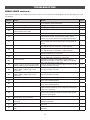
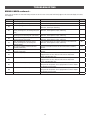
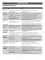
TABLE OF CONTENTS
SAFETY
1
OPERATION
SAFETY SYMBOL AND SIGNAL WORD REVIEW .....................................1
USAGE CLASS ..........................................................................................2
UL325 ENTRAPMENT PROTECTION REQUIREMENTS .............................2
SAFETY INSTALLATION INFORMATION ...................................................3
GATE CONSTRUCTION INFORMATION .....................................................4
INTRODUCTION
28
CONTROL BOARD OVERVIEW ................................................................28
MANUAL RELEASE .................................................................................29
RESET BUTTON ......................................................................................29
PARTY MODE .........................................................................................29
OPERATOR ALARM ...............................................................................30
REMOTE CONTROL ................................................................................30
5
CARTON INVENTORY ...............................................................................5
SPECIFICATIONS ......................................................................................6
SITE PREPARATION .................................................................................7
CHECK YOUR GATE ..................................................................................7
OVERVIEW OF TYPICAL INSTALLATION ..................................................8
ACCESSORY WIRING
INSTALLATION
MAINTENANCE
31
EXTERNAL CONTROL DEVICES ..............................................................31
VEHICLE DETECTION DEVICES ..............................................................31
LOCKS ....................................................................................................32
MISCELLANEOUS WIRING .....................................................................32
9
33
IMPORTANT SAFETY INFORMATION .......................................................9
INSTALLATION TIPS.................................................................................9
ATTACH BRACKETS TO OPERATOR .......................................................10
DETERMINE MOUNTING LOCATION ......................................................11
POSITION THE OPERATOR .....................................................................12
SECURE THE BRACKETS ........................................................................13
INSTALL THE CONTROL BOX .................................................................14
EARTH GROUND ROD ............................................................................16
WIRE THE OPERATOR ARM TO THE CONTROL BOARD ........................16
DUAL GATES ONLY ................................................................................17
INSTALL ENTRAPMENT PROTECTION ...................................................20
POWER WIRING .....................................................................................22
FINISH INSTALL .....................................................................................23
IMPORTANT SAFETY INFORMATION .....................................................33
MAINTENANCE CHART ...........................................................................33
BATTERIES .............................................................................................33
ADJUSTMENT
CONTROL BOX........................................................................................48
GATE OPERATOR ARM ...........................................................................48
TROUBLESHOOTING
APPENDIX
41
BRACKET TYPES ....................................................................................41
SOLAR PANEL(S) ...................................................................................42
LIMIT SETUP WITH A REMOTE CONTROL .............................................47
REPAIR PARTS
23
LIMIT AND FORCE ADJUSTMENT ..........................................................23
OBSTRUCTION TEST ..............................................................................25
PROGRAMMING
34
ERROR CODES .......................................................................................34
CONTROL BOARD LEDS .........................................................................37
TROUBLESHOOTING CHART ..................................................................38
48
WIRING DIAGRAM
49
STANDARD CONTROL BOX ....................................................................49
26
REMOTE CONTROLS (NOT PROVIDED) .................................................26
LIFTMASTER INTERNET GATEWAY
(NOT PROVIDED)....................................................................................27
ERASE ALL CODES .................................................................................27
ERASE LIMITS ........................................................................................27
TO REMOVE AND ERASE MONITORED ENTRAPMENT PROTECTION
DEVICES .................................................................................................27
ACCESSORIES
50
WARRANTY
51
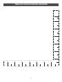
TEMPLATE FOR POST BRACKET MOUNTING
52
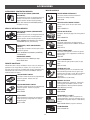
SAFETY
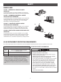
SAFETY SYMBOL AND SIGNAL WORD REVIEW
When you see these Safety Symbols and Signal Words on the following pages, they will alert
you to the possibility of Serious Injury or Death if you do not comply with the warnings that
accompany them. The hazard may come from something mechanical or from electric shock.
Read the warnings carefully.
MECHANICAL
When you see this Signal Word on the following pages, it will alert you to the possibility of
damage to your gate and/or the gate operator if you do not comply with the cautionary
statements that accompany it. Read them carefully.
ELECTRICAL
IMPORTANT NOTE:
•
BEFORE attempting to install, operate or maintain the operator, you must read and fully
understand this manual and follow all safety instructions.
•
DO NOT attempt repair or service of your gate operator unless you are an Authorized
Service Technician.
1
SAFETY
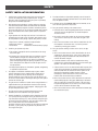
USAGE CLASS
CLASS I – RESIDENTIAL VEHICULAR GATE
OPERATOR
I
A vehicular gate operator (or system) intended for use in garages or
parking areas associated with a residence of one-to four single families.
CLASS II – COMMERCIAL/GENERAL ACCESS
VEHICULAR GATE OPERATOR
II
A vehicular gate operator (or system) intended for use in a commercial
location or building such as a multi-family housing unit (five or more
single family units), hotel, garages, retail store, or other buildings
accessible by or servicing the general public.
CLASS III – INDUSTRIAL/LIMITED ACCESS
VEHICULAR GATE OPERATOR
III
A vehicular gate operator (or system) intended for use in an industrial
location or building such as a factory or loading dock area or other
locations not accessible by or intended to service the general public.
CLASS IV– RESTRICTED ACCESS VEHICULAR GATE
OPERATOR
IV
A vehicular gate operator (or system) intended for use in a guarded
industrial location or building such as an airport security area or other
restricted access locations not servicing the general public, in which
unauthorized access is prevented via supervision by security personnel.
UL325 ENTRAPMENT PROTECTION REQUIREMENTS
This vehicular gate operator must be installed with at least two independent entrapment protection means as specified in the table below.
IMPORTANT SAFETY INFORMATION
HORIZONTAL SLIDE AND SWING GATE OPERATOR
GATE OPERATOR ENTRAPMENT PROTECTION TYPES
Type A
Inherent (built into the operator) entrapment
protection system
Type B1
Non-contact sensors such as photoelectric sensors
Type B2
Contact sensors such as edge sensors
To reduce the risk of INJURY or DEATH:
• READ AND FOLLOW ALL INSTRUCTIONS.
• NEVER let children operate or play with gate controls. Keep the
remote control away from children.
• ALWAYS keep people and objects away from the gate. NO ONE
SHOULD CROSS THE PATH OF THE MOVING GATE.
• Test the gate operator monthly. The gate MUST reverse on contact
with a rigid object or reverse when an object activates the noncontact sensors. After adjusting the force or the limit of travel,
retest the gate operator. Failure to adjust and retest the gate
operator properly can increase the risk of INJURY or DEATH.
• Use the emergency release ONLY when the gate is not moving.
• KEEP GATES PROPERLY MAINTAINED. Read the owner’s manual.
Have a qualified service person make repairs to gate hardware.
• The entrance is for vehicles ONLY. Pedestrians MUST use separate
entrance.
• SAVE THESE INSTRUCTIONS.
The same type of device shall not be used for both entrapment
protection means. Use of a single device to cover both the opening
and closing directions is in accordance with the requirement;
however, a single device is not required to cover both directions.
This operator is provided with Type A. The installer is required to
install additional entrapment protection devices in each entrapment
zone.
2
SAFETY
SAFETY INSTALLATION INFORMATION
1.
Vehicular gate systems provide convenience and security. Gate
systems are comprised of many component parts. The gate
operator is only one component. Each gate system is specifically
designed for an individual application.
2.
Gate operating system designers, installers and users must take
into account the possible hazards associated with each individual
application. Improperly designed, installed or maintained systems
can create risks for the user as well as the bystander. Gate systems
design and installation must reduce public exposure to potential
hazards.
3.
4.
9.
10. A minimum of two (2) WARNING SIGNS shall be installed, one on
each side of the gate where easily visible.
11. For a gate operator utilizing a non-contact sensor:
a. Reference owner’s manual regarding placement of non-contact
sensor for each type of application. See Install Entrapment
Protection section.
A gate operator can create high levels of force in its function as a
component part of a gate system. Therefore, safety features must
be incorporated into every design. Specific safety features include:
b. Care shall be exercised to reduce the risk of nuisance tripping,
such as when a vehicle trips the sensor while the gate is still
moving.
• Edges Sensors (contact) • Guards for Exposed Rollers
• Photoelectric Sensors • Screen Mesh
• Vertical Posts
• Instructional and Precautionary Signage
c. One or more non-contact sensors shall be located where the risk
of entrapment or obstruction exists, such as the perimeter
reachable by a moving gate or barrier.
12. For a gate operator utilizing a contact sensor such as an edge
sensor:
Install the gate operator only when:
a. The operator is appropriate for the construction and the usage
class of the gate.
a. One or more contact sensors shall be located where the risk of
entrapment or obstruction exists, such as at the leading edge,
trailing edge and post mounted both inside and outside of a
vehicular horizontal slide gate.
b. All openings of a horizontal slide gate are guarded or screened
from the bottom of the gate to a minimum of 6 feet (1.8 m)
above the ground to prevent a 2-1/4 inches (6 cm) diameter
sphere from passing through the openings anywhere in the gate,
and in that portion of the adjacent fence that the gate covers in
the open position.
b. A hard wired contact sensor shall be located and its wiring
arranged so the communication between the sensor and the gate
operator is not subject to mechanical damage.
c. A wireless device such as one that transmits radio frequency (RF)
signals to the gate operator for entrapment protection functions
shall be located where the transmission of the signals are not
obstructed or impeded by building structures, natural
landscaping or similar obstruction. A wireless device shall
function under the intended end-use conditions.
c. All exposed pinch points are eliminated or guarded, and guarding
is supplied for exposed rollers.
5.
6.
The Stop and/or Reset (if provided separately) must be located in
the line-of-sight of the gate. Activation of the reset control shall not
cause the operator to start.
The operator is intended for installation only on gates used for
vehicles. Pedestrians must be supplied with a separate access
opening. The pedestrian access opening shall be designed to
promote pedestrian usage. Locate the gate such that persons will
not come in contact with the vehicular gate during the entire path of
travel of the vehicular gate.
d. One or more contact sensors shall be located on the inside and
outside leading edge of a swing gate. Additionally, if the bottom
edge of a swing gate is greater than 6 inches (152 mm) above
the ground at any point in its arc of travel, one or more contact
sensors shall be located on the bottom edge.
The gate must be installed in a location so that enough clearance is
supplied between the gate and adjacent structures when opening
and closing to reduce the risk of entrapment. Swinging gates shall
not open into public access areas.
7.
The gate must be properly installed and work freely in both
directions prior to the installation of the gate operator.
8.
Controls intended for user activation must be located at least 6 feet
(1.8 m) away from any moving part of the gate and where the user
is prevented from reaching over, under, around or through the gate
to operate the controls. Outdoor or easily accessible controls shall
have a security feature to prevent unauthorized use.
Exception: Emergency access controls only accessible by authorized
personnel (e.g. fire, police) may be placed at any location in the
line-of-sight of the gate.
e. One or more contact sensors shall be located at the bottom edge
of a vertical barrier (arm).
3
SAFETY
GATE CONSTRUCTION INFORMATION
Vehicular gates should be installed in accordance with ASTM F2200: Standard Specification for Automated Vehicular Gate Construction. For a copy,
contact ASTM directly at 610-832-9585 or www.astm.org.
1.
GENERAL REQUIREMENTS
1.1
Gates shall be constructed in accordance with the provisions
given for the appropriate gate type listed, refer to ASTM F2200 for
additional gate types.
1.2
Gates shall be designed, constructed and installed to not fall over
more than 45 degrees from the vertical plane, when a gate is
detached from the supporting hardware.
1.3
Gates shall have smooth bottom edges, with vertical bottom
edged protrusions not exceeding 0.50 inches (12.7 mm) when
other than the exceptions listed in ASTM F2200.
1.4
The minimum height for barbed tape shall not be less than 8 feet
(2.44 m) above grade and for barbed wire shall not be less than 6
feet (1.83 m) above grade.
1.5
An existing gate latch shall be disabled when a manually operated
gate is retrofitted with a powered gate operator.
1.6
A gate latch shall not be installed on an automatically operated
gate.
1.7
Protrusions shall not be permitted on any gate, refer to ASTM
F2200 for Exceptions.
1.8
Gates shall be designed, constructed and installed such that their
movement shall not be initiated by gravity when an automatic
operator is disconnected, in accordance with the following.
1.8.1
Vehicular horizontal slide gate. Shall not result in continuous,
unimpeded movement in either lineal direction of its travel.
1.8.2
Vehicular horizontal swing gate. Shall not result in continuous,
unimpeded movement in either direction along the arc of its path
of travel.
1.9
For pedestrian access in the vicinity of an automated vehicular
gate, a separate pedestrian gate shall be provided. The pedestrian
gate shall be installed in a location such that a pedestrian shall
not come in contact with a moving vehicular access gate. A
pedestrian gate shall not be incorporated into an automated
vehicular gate panel.
2.
SPECIFIC APPLICATIONS
2.1
Any non-automated gate that is to be automated shall be
upgraded to conform to the provisions of this specification.
2.2
This specification shall not apply to gates generally used for
pedestrian access and to vehicular gates not to be automated.
2.3
Any existing automated gate, when the operator requires
replacement, shall be upgraded to conform to the provisions of
this specification in effect at that time.
3.1.2
All openings shall be designed, guarded, or screened from the
bottom of the gate to the top of the gate or a minimum of 72 in.
(1.83 m) above grade, whichever is less, to prevent a 2 1⁄4 in.
(57 mm) diameter sphere from passing through the openings
anywhere in the gate, and in that portion of the adjacent fence
that the gate covers in the open position. The gate panel shall
include the entire section of the moving gate,including any back
frame or counterbalance portion of the gate.
3.1.3
A gap, measured in the horizontal plane parallel to the roadway,
between a fixed stationary object nearest the roadway, (such as a
gate support post) and the gate frame when the gate is in either
the fully open position or the fully closed position, shall not
exceed 2 1/4 inches (57 mm), refer to ASTM F2200 for Exception.
3.1.4
Positive stops shall be required to limit travel to the designed fully
open and fully closed positions. These stops shall be installed at
either the top of the gate, or at the bottom of the gate where such
stops shall horizontally or vertically project no more than is
required to perform their intended function.
3.1.5
All gates shall be designed with sufficient lateral stability to
assure that the gate will enter a receiver guide, refer to ASTM
F2200 for panel types.
3.2
The following provisions shall apply to Class IV vehicular
horizontal slide gates:
3.2.1
All weight bearing exposed rollers 8 feet (2.44 m), or less, above
grade shall be guarded or covered.
3.2.2
Positive stops shall be required to limit travel to the designed fully
open and fully closed positions. These stops shall be installed at
either the top of the gate, or at the bottom of the gate where such
stops shall horizontally or vertically project no more than is
required to perform their intended function.
4.
VEHICULAR HORIZONTAL SWING GATES
4.1
The following provisions shall apply to Class 1, Class II and Class
III vehicular horizontal swing gates:
4.1.1
Gates shall be designed, constructed and installed so as not to
create an entrapment area between the gate and the supporting
structure or other fixed object when the gate moves toward the
fully open position, subject to the provisions in 4.1.1.1 and
4.1.1.2.
4.1.1.1 The width of an object (such as a wall, pillar or column) covered
by a swing gate when in the open position shall not exceed 4
inches (102 mm), measured from the center line of the pivot
point of the gate, refer to ASTM F2200 for exception.
3.
VEHICULAR HORIZONTAL SLIDE GATES
4.1.1.2 Except for the zone specified in Section 4.1.1.1, the distance
between a fixed object such as a wall, pillar or column, and a
swing gate when in the open position shall not be less than 16
inches (406 mm), refer to ASTM F2200 for exception.
3.1
The following provisions shall apply to Class I, Class II and Class
III vehicular horizontal slide gates:
4.2
3.1.1
All weight bearing exposed rollers 8 feet (2.44 m), or less, above
grade shall be guarded or covered.
4
Class IV vehicular horizontal swing gates shall be designed,
constructed and installed in accordance with security related
parameters specific to the application in question.
INTRODUCTION
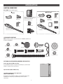
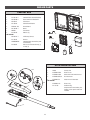
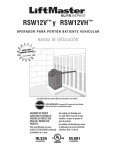
CARTON INVENTORY
NOT SHOWN: Documentation packet
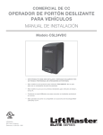
LA400DCS ONLY
LA400DC
Pull-to-Open Bracket
Standard Control Box with 2 Batteries and
hardware bag (watertight connector (4),
30 amp fuse (2), mounting bolt,
washer (4), and wire nut (3))
Gate Bracket
Pull-to-Open Bracket
Motor Cable
Six Conductor,
40 feet (12.2 m)
Gate Bracket
Post Bracket
Terminal Block
Plug-in Transformer
Post Bracket
Junction Box
Connector
Gate Operator
(with a 6 foot cable attached)
Gate Operator
Warning Signs (2)
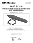
HARDWARE INVENTORY
NOTE: Hardware quantities shown below are for LA400DC. Quantities are
doubled for LA400DCS.
Flat Washer 5/16" (1)
Hex Nut 5/16"-18 (1)
Key (2)
Keylock Cap
Flat Washer 3/8" (3)
Lock Washer 5/16" (1)
Hex Bolt 5/16"-18 x 1-1/2" (1)
Hex Bolt 3/8"-16 x 1-1/2" (1)
Pin (2)
Lock Washer 3/8" (3)
Hex Nut 3/8"-16 (3)
Carriage Bolt 3/8" x 5-15/16" (2)
OPTIONAL ACCESSORIES (ORDERED SEPARATELY)
Push-to-Open Bracket (Model 50-19503)
If your application requires the gate to be pushed open, a push-to-open
bracket is required (refer to accessories).
Expansion Board (Model K1D8080-1CC)
Large Metal Control Box for Solar Applications
(Model XLSOLARCONTDC)
Required for solar installations (batteries not included). Requires two
33AH batteries, battery tray, and solar battery harness (refer to
accessories).
5
Hairpin Clip (2)
INTRODUCTION
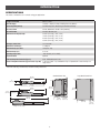
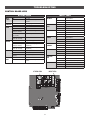
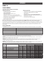
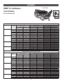
SPECIFICATIONS
This model is intended for use in vehicular swing gate applications:
Usage Classification
Class I, II, & III
Main AC Supply
120 Vac, .5 Amps (6.5 Amps including Accessory Outlets)
System Operating Voltage
24 Vdc Battery Run / Direct Plug-in Transformer Charge
Accessory Power
24 Vdc, 500mA max. for ON + SW (switched)
Solar Power Max
24 Vdc at 60 watts max.
Maximum Gate Weight/Length
850 lbs. (385.6 kg) / 10 ft (3.0 m)
750 lbs. (340.2 kg) / 12 ft (3.7 m)
650 lbs. (294.8 kg) / 14 ft (4.3 m)
550 lbs. (249.5 kg) / 16 ft (4.9 m)
90 Degree Travel Time*
15-18 seconds
Maximum Travel Range*
115 degrees
Maximum Daily Cycle Rate
100 cycles / day
Maximum Duty Cycle
4 min on
Operating Temperature
-20°C to 60°C (-4°F to 140°F)
Expansion Board
Optional
Inherent Entrapment Protection (Type A)
Dual - RPM and Current Sense
External Entrapment Protection (Type B1 and/or Type B2)
3 inputs per board - any combination of up to 3 photoelectric sensors and up to 2
edge sensors
*Travel time and range are affected by A and B mounting dimensions
Standard Control Box
36-5/16"
(92.2 cm)
Large Metal Control Box
4"
(10.2 cm)
1/2" DIA.
(1.3 cm DIA.)
37-3/8"
(94.9 cm)
4-1/2"
(11.2 cm)
16-7/16"
(41.8 cm)
20-3/4"
(52.7 cm)
1/4"
(0.635 cm)
53-1/2"
(136 cm)
14-3/8"
(36.5 cm)
6-9/16"
(16.7 cm)
17-3/16"
(43.7 cm)
Weight: 13.2 lbs. (6 kg.)
6
6-3/16"
(15.7 cm)
INTRODUCTION
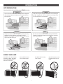
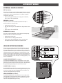
SITE PREPARATION
Check the national and local building codes BEFORE installation.
LOOPS
TRENCH
Trench and install conduit. Before trenching, contact underground
utility locating companies. Conduit must be UL approved for low
and high voltage.
Loops allow the gate to stay open when vehicles are obstructing the
gate path. Suggested for vehicles 14 feet (4.27 m) or longer. Loops
are not required but are recommended.
(Inside Property)
Conduit
SAFETY
GATE
Entrapment protection devices are required to protect against any
entrapment or safety conditions encountered in your gate
application (refer to pages 19-20 for more details). Install warning
signs on both sides of the gate.
Gate must be constructed and installed according to ASTM F2200
standards (refer to page 4). Gate must fit specifications of operator
(refer to specifications).
Warning Signs
Entrapment Danger
CHECK YOUR GATE
Gate MUST be level. Gate and gate
post MUST be plumb. Gate MUST
have a smooth bottom edge, no
protrusions should exist.
Remove ANY/ALL wheels
from the bottom of gate.
Gate MUST NOT hit or drag
across ground.
7
Gate MUST swing freely and
be supported entirely by its
hinges.
INTRODUCTION
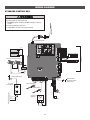
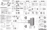
OVERVIEW OF TYPICAL INSTALLATION
Identify your installation type (refer to the Appendix in the back of the manual for more information). All the illustrations on the following pages
display a typical Left-Hand Gate installation with a pull-to-open bracket. For Push-to-Open applications refer to the Appendix.
SINGLE GATE
Warning Sign
Operator
NOTE: One or more non-contact
sensors shall be located where the
risk of entrapment or obstruction
exists at either the opening or
closing direction. Care shall be
exercised to reduce the risk of
nuisance tripping, such as when a
vehicle, trips the sensor while the
gate is still moving.
Photoelectric
Sensors
Control Box
Edge Sensors
Photoelectric
Sensors
Water Tight Conduit (Not provided)
NOTE: Power and control wiring
MUST be run in separate conduits.
Earth Ground Rod
Photoelectric
Sensors
Check national and local
codes for proper depth
DUAL GATE
Secondary Operator
Junction
Box
Warning Sign
Photoelectric Sensors
Edge Sensor
Warning Sign
Primary Operator
Photoelectric Sensors
Control Box
Photoelectric
Sensors
Water Tight Conduit (Not provided)
NOTE: Power and control wiring
MUST be run in separate conduits.
Edge Sensor
Photoelectric Sensors
Earth Ground Rod
Check national and local
codes for proper depth
8
INSTALLATION
IMPORTANT SAFETY INFORMATION
To prevent SERIOUS INJURY or DEATH from a moving gate:
• Pinch points must be guarded at all times. Install enclosed-style gate
tracks and roller guards.
• Place screen mesh 6 feet (1.8 m) high on the gate to prevent access
through openings anywhere the gate may travel.
• Mount controls at least 6 feet (1.8 m) from the gate or ANY moving
part of the gate.
• Install Warning signs on EACH side of gate in PLAIN VIEW.
Permanently secure each Warning sign in a suitable manner using
fastening holes.
• This operator is intended for vehicular use only. To prevent INJURY
to pedestrians, a separate pedestrian access should be supplied,
visible from the gate. Locate the pedestrian access where there is not
a chance of INJURY at any point during full movement of the gate.
• Contact sensors MUST be located at the leading and trailing edges,
and post mounted both inside and outside a horizontal swing gate.
Non-contact sensors such as photoelectric sensors MUST be
mounted across the gate opening and operate during BOTH the open
and close cycles.
• Entrapment protection devices MUST be installed to protect anyone
who may come near a moving gate.
• Locate entrapment protection devices to protect in BOTH the open
and close gate cycles.
• Locate entrapment protection devices to protect between moving
gate and RIGID objects, such as posts or walls.
• Too much force on gate will interfere with proper operation of safety
reversal system.
• NEVER increase force beyond minimum amount required to move
gate.
• NEVER use force adjustments to compensate for a binding or
sticking gate.
• If one control (force or travel limits) is adjusted, the other control
may also need adjustment.
• After ANY adjustments are made, the safety reversal system MUST
be tested. Gate MUST reverse on contact with a rigid object.
• To AVOID damaging gas, power or other underground utility lines,
contact underground utility locating companies BEFORE digging
more than 18 inches (46 cm) deep.
• ALWAYS wear protective gloves and eye protection when changing
the battery or working around the battery compartment.
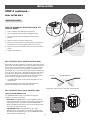
INSTALLATION TIPS
DO's
• Weld a horizontal bar across entire gate on any installation for
strength. Make sure that the operator is mounted level or it will not
function properly.
• The operator can be mounted on top of the gate frame.
• The operator must be installed at least 12 inches from the ground.
• Make sure there is slack in the operator cable.
Operator Cable
DON'Ts
• DO NOT install upside down.
• DO NOT install on ANY pedestrian passageways, doorways, or gates.
• DO NOT install next to sprinklers or any area that may expose the
bottom of operator to water.
• DO NOT over-bend the operator cable. Doing this will cause the wires
to eventually break.
• DO NOT install on uphill or downhill gates.
• DO NOT weld the crossbar on just a few pickets, or they could bend.
9
INSTALLATION
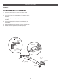
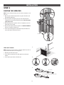
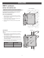
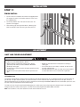
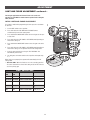
STEP 1
ATTACH BRACKETS TO OPERATOR
1. Insert the key into the lock on the release lever and turn it 180°
counterclockwise.
2. Turn the release lever 180° counterclockwise. The operator is now in
manual mode.
3. Assemble gate post bracket by placing pull-to-open bracket on top of
post bracket.
4. Insert the bolt through both brackets and secure with washer, lock
washer and nut.
5. Attach post bracket assembly to operator using pins and hairpin clips.
6. Attach gate bracket to operator using pins and hairpin clips.
Hex Bolt 3/8"
Extension
Bracket
Release Lever
Post Bracket
Washer
Lock Washer
Nut
Pin
Pin
Post Bracket Assembly
Gate Bracket
Hairpin Clip
Hairpin Clip
10
INSTALLATION
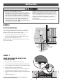
STEP 2
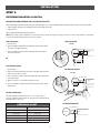
DETERMINE MOUNTING LOCATION
MEASURING AND MARKING FOR THE GATE BRACKET
Before proceeding, begin with the gate in the fully closed position. There are two methods for determining the proper location of the post brackets:
•
Paper template (Located on the back page of this manual. Must be cut out.)
•
Tape measure.
Either method will work depending on preference.
NOTE: There should only be a maximum of 4" (10.2 cm) from the center of the hinge to the edge of the post or column. If the distance is greater than
4" (10.2 cm) entrapment protection for this area is required.
TEMPLATE METHOD
TEMPLATE METHOD
1. Close the gate.
TOP VIEW
2. Place the template (provided on the back page of this manual) under
the center of the gate hinge point.
Gate Post
3. Use a screwdriver or dowel rod to temporarily mark the location in
front of the gate post.
Gate Hinge Point
Gate
4" (10.2 cm)
maximum
OR
TAPE MEASURE METHOD
1. Close the gate.
TAPE MEASURE METHOD
2. Place the measuring tape under the center of the gate hinge point and
measure out 7 inches (17.8 cm).
TOP VIEW
3. Use a screwdriver or dowel rod to temporarily mark the location of the
first measurement.
Gate Hinge Point
Gate Post
Gate
4. Measure 7 inches (17.8 cm) from the previous mark.
4" (10.2 cm)
maximum
5. Use the screwdriver or dowel rod to mark the location of the second
measurement.
7" (17.8 cm)
ALTERNATE DIMENSIONS
The ideal installation measurements are A = 7" (17.8 cm) and B = 7"
(17.8 cm). If different measurements are used, the sum of A and B cannot
be greater than 15" (38.1 cm).
7" (17.8 cm)
ALTERNATE DIMENSIONS
DIMENSION CHART
A
B
7" (17.8 cm)
7" (17.8 cm)
8" (20.3 cm)
6" (15.2 cm)
7-1/2" (19.1 cm)
7-1/2" (19.1 cm)
6-1/2" (16.5 cm)
6-1/2" (16.5 cm)
6" (15.2 cm)
6" (15.2 cm)
Gate Hinge Point
Gate Post
Gate
(A)
(B)
11
INSTALLATION
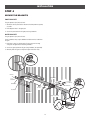
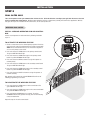
STEP 3
POSITION THE OPERATOR
NOTE: The post bracket assembly can be mounted several places on the
gate post.
1. Open the gate to desired open position (no greater than 100°) and
hold operator against gate.
2. Place the operator arm against gate post at the desired position.
Temporarily secure gate post bracket with clamp. The gate operator
(arm) must be level.
3. Mark mounting holes on gate for reference. Temporarily secure the
gate bracket using a clamp.
4. Align the pull-to-open bracket to a position as CLOSE AS POSSIBLE
above the screwdriver or dowel rod.
5. Insert hex bolt through pull-to-open bracket and post bracket and
secure with washer, lock washer and nut.
Screwdriver
1
TEST GATE TRAVEL
NOTE: If gate does not open and close completely adjust the position of
the gate bracket and mark new mounting holes.
1. Manually open and close the gate.
2. Ensure that the operator does not bind against the pull-to-open
bracket.
3. Ensure that the piston does not bottom out.
2
3
1/2" (1.3 cm)
Do not allow piston to fully extend or fully retract.
1/2" (1.3 cm)
12
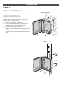
INSTALLATION
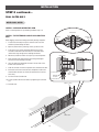
STEP 4
SECURE THE BRACKETS
POST BRACKET
The gate operator (arm) must be level.
1. Mark holes for the post bracket. Remove the clamp and the operator,
set aside.
2. Drill adequate holes in the gate post.
3. Secure the post bracket to the gate post using hardware.
GATE BRACKET
The gate operator (arm) must be level.
Some installations may require additional reinforcement be installed on
the gate.
1. Drill holes in gate (or reinforcement, if necessary) that are large
enough for the gate bracket mounting hardware.
2. Secure the gate operator to the gate using hardware (not provided).
3. Manually move the gate to verify that it opens and closes fully.
Welder (Optional)
Hex Nuts
Gate Bracket
Lock
Washers
Hex Nut
Lock Washer
Flat Washers
Flat Washer
Welder (Optional)
Hex Bolt
Post Bracket
Carriage Bolts
Angle
Iron
Reinforcement Area
OR
Flat Bar
Wood
OR
13
INSTALLATION
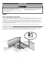
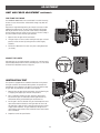
STEP 5
INSTALL THE CONTROL BOX
WALL OR COLUMN MOUNT
For Large Metal Control Box installation, refer to the following page.
STANDARD CONTROL BOX
The control box MUST be mounted within 5 feet (1.52 m) of the gate
operator. Mount the control box as high as possible for best radio
reception. Make sure the control box is level.
1.
Remove the screws and open the control box.
2.
Select the mounting holes (according to your application) and
remove the knockouts using a screwdriver and hammer.
3.
9 1/8"
13 3/4"
Secure the control box to mounting surface.
A. Wall or Column: Use the provided screws (4).
B. Post: Use U-bolts and rubber washers (not provided) to ensure a
watertight seal. Make sure the U-bolts do not protrude more than
3/4 inch from the control box because this can short the control
board.
POST MOUNT
6 3/8"
4 3/8"
3 7/8"
5 7/8"
4 7/8"
2 7/8"
12 1/16"
14
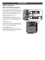
INSTALLATION
STEP 5 continued...
INSTALL THE CONTROL BOX
WALL OR COLUMN MOUNT
LARGE METAL CONTROL BOX (XLSOLARCONTDC)
The control box MUST be mounted within 5 feet (1.52 m) of the gate
operator. Mount the control box as high as possible for best radio
reception. Make sure the control box is level.
WALL OR COLUMN MOUNT
1.
Open the control box. The control box door may be removed by
opening the door 90°. Lift the door from the hinges and set aside
until the installation is complete.
2.
Use knock outs located at the 4 corners of the control box and
knock out using a screwdriver and hammer.
3.
Secure the control box to mounting surface using the provided
screws (4).
POST MOUNT
POST MOUNT
NOTE: The post mount option is not recommended for the 33AH battery
application.
1.
Open the control box. The control box door may be removed by
opening the door 90°. Lift the door from the hinges and set aside
until the installation is complete.
2.
The control box can be mounted to a post with 'U' bolts (refer to
chart). The knock out will accommodate a 3/8" diameter 'U' bolt.
Select center mounting holes (top and bottom) and knock out using
a screwdriver and hammer.
3.
Secure the control box to mounting surface with U-bolts and rubber
washers (not provided) to ensure a watertight seal.
TYPE AND SIZE
'U' BOLT OPENING
Standard 3" Round Pipe
3-1/2"
Standard 4" Square Post
4"
Standard 6" Square Post
6"
15
INSTALLATION
• ALL electrical connections MUST be made by a qualified individual.
• DO NOT install ANY wiring or attempt to run the operator without
consulting the wiring diagram. We recommend that you install an
edge sensor BEFORE proceeding with the control station installation.
• ALL power wiring should be on a dedicated circuit and well
protected. The location of the power disconnect should be visible
and clearly labeled.
• ALL power and control wiring MUST be run in separate conduit.
To reduce the risk of SEVERE INJURY or DEATH:
• ANY maintenance to the operator or in the area near the operator
MUST NOT be performed until disconnecting the electrical power (AC
or solar and battery) and locking-out the power via the operator
power switch. Upon completion of maintenance the area MUST be
cleared and secured, at that time the unit may be returned to service.
• Disconnect power at the fuse box BEFORE proceeding. Operator
MUST be properly grounded and connected in accordance with
national and local electrical codes. NOTE: The operator should be on
a separate fused line of adequate capacity.
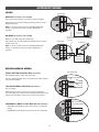
STEP 6
EARTH GROUND ROD
Use the proper earth ground rod for your local area. The ground wire
must be a single, whole piece of wire. Never splice two wires for the
ground wire. If you should cut the ground wire too short, break it, or
destroy its integrity, replace it with a single wire length.
1.
Install the earth ground rod within 3 feet of the control box.
2.
Run wire from the earth ground rod to the control box. The earth
ground wire will be connected in a later step.
Control Box
12 Gauge Wire
NOTE: If the operator is not grounded properly the range of the remote
controls will be reduced.
Check national
and local codes
for proper
depth
Earth Ground Rod (Within 3'
(0.9 m) of control box)
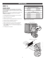
STEP 7
WIRE THE OPERATOR ARM TO THE
CONTROL BOARD
2.
Insert the operator cable through the provided watertight connector.
3.
Insert the operator cable and watertight connector into the knockout.
4.
Slide the connector nut onto the operator cable.
5.
Connect the operator cable wires to the connector according to the
colored label on the connector (white to white, red to red, etc.).
6
Plug the connector into the GATE 1 terminal on the control board as
shown.
7.
Tighten the connector nut.
GATE 2
Choose a knockout in the bottom of the control box.
GATE 1
1.
(control board)
Connector
Operator Cable
Watertight
Connector
If installing one operator, proceed to page 19. If installing two
operators, go to the following page.
16
Connector
Nut
INSTALLATION
STEP 8
DUAL GATES ONLY
There are two options for dual gate communication: wired or wireless. Follow the directions according to your application. Do not use wired and
wireless communication simultaneously. Wired dual gate applications will have a longer battery standby time than wireless applications. Wireless
dual gates will require the installation of two control boxes, one for each operator arm.
WIRELESS DUAL GATES
INSTALL A SECOND OPERATOR ARM AND CONTROL
BOX
Install a second operator arm and control box by following installation
steps 1-7.
LEARN
T
BUT
XMITTER
NETWORK
TO ACTIVATE THE WIRELESS FEATURE
REVERSAL
FORCE
1. Choose a control box to be the network primary operator. All wireless
accessories will need to be programmed to the primary control board.
NOTE: We recommend that all accessories and board configurations
are set on the primary control board.
TEST
BUTTONS
XMITTER
OPEN
NETWORK
CLOSE
RSAL
RCE
STOP
2. Press and release the LEARN button on the primary control board.
The green XMITTER LED will light.
MAX
3. Press and release the LEARN button again on the primary control
board. The yellow NETWORK LED will light.
4. Press and release the OPEN test button to assign this operator as
network primary.
5. Press and release the LEARN button on the secondary control board.
The green XMITTER LED will light.
6. Press and release the LEARN button again on the secondary control
board. The yellow NETWORK LED will light.
Cau
Canth
se
e
Gat Dea at any
ing ry or move
MovInju Gate mayng. gate or
R! warni the
CLEAut prior operate
ce
en
KEEPwitho
es onlyentran
time let childrarea.
vehicl ate
not gate
Do in the is for separ
use
ce
play
entran must
This trians
Pedes
7. Press and release the CLOSE test button to assign this operator as
network secondary.
Both operators will beep and the yellow NETWORK LEDs will turn off
indicating programming is successful.
se
Cau
e Canth
Gat Dea at any
ing ry or move
MovInju Gate mayng. gate or
R! warni the
CLEAut prior operate
ce
en
KEEPwitho
es onlyentran
time let childrarea.
vehicl ate
not gate
Do in the is foruse separ
ce
play
entran must
This trians
Pedes
TO DEACTIVATE THE WIRELESS FEATURE:
1. Press and release the LEARN button on either control board. The
green XMITTER LED will light.
2. Press and release the LEARN button again on the same control board.
The yellow NETWORK LED will light.
3. Press and hold the LEARN button for 5 seconds. The yellow
NETWORK LED will blink (operator will beep) then turn off indicating
successful deactivation.
Repeat the steps for the other control board.
17
INSTALLATION
STEP 8 continued...
DUAL GATES ONLY
WIRED DUAL GATES
INSTALL A SECOND OPERATOR ARM
Install a second operator arm by following installation steps 1-4.
Terminal Block
INSTALL THE EXTENSION CABLE AND JUNCTION
BOX
Operator
Cable
Before digging, contact local underground utility locating companies.
1.
Trench across driveway to bury the extension cable. Use PVC
conduit to prevent damage to cables.
2.
Open the junction box by removing screws (4) and set aside.
3.
Select holes to be used for mounting and knock out using a
screwdriver and hammer. Drill two holes in the bottom of the
junction box large enough for the watertight connectors.
4.
Mount the junction box within 3 feet (0.9 m) of second operator.
5.
Route operator cable and extension cable through watertight
connector nut and watertight connector.
6.
Insert the cables and watertight connectors into the holes in the
bottom of the junction box.
7.
Slide the connector nut onto the operator cable and extension cable.
8.
Connect the wires from extension cable and operator cable to the
terminal block connector as shown (like-colored wires must face
each other).
9.
Brown
Brown
Green
Green
White
White
Yellow
Yellow
Blue
Blue
Red
Red
Mounting Slot
Connector Nut
Operator
Cable
Watertight
Connector
Put wires inside of junction box.
Connector Nut
10. Secure operator and extension cables by tightening the connector
nut.
Within 3' (0.9 m)
11. Reinstall cover.
Can
se
Cau
th
Gate Dea at any
ing ry or move
Mov Inju Gate mayng. gate or
R! warni the
CLEAut prior operate
ce
en
KEEPwitho
es onlyentran
time let childrarea.
vehicl ate
not gate
Do in the is for separ
use
ce
play
entran must
This trians
Pedes
se
Cau
Can th
Gate Dea at any
ing ry or move
Mov Inju Gate mayng. gate or
R! warni the
CLEAut prior operate
ce
en
KEEPwitho
es onlyentran
time let childrarea.
vehicl ate
not gate
Do in the is for separ
use
ce
play
entran must
This trians
Pedes
PVC Conduit
18
Extension
Cable
Extension
Cable
INSTALLATION
STEP 8 continued...
DUAL GATES ONLY
(Control Board)
WIRE THE SECONDARY OPERATOR ARM TO THE
CONTROL BOARD
Watertight
Connector
1.
Choose a knockout in the bottom of the control box.
Extension
Cable
2.
Insert the extension cable through the watertight connector.
3.
Insert the extension cable and watertight connector into the
knockout.
4.
Slide the connector nut onto the operator cable.
5.
Connect the extension cable wires to the connector according to the
colored label on the connector (white to white, red to red, etc.).
6.
Plug the connector into the GATE 2 terminal on the control board as
shown.
7.
Tighten the connector nut.
GATE 2
GATE 1
WIRED DUAL GATES
Connector
Connector Nut
Caus
Can h
e
Gate Deat at any
ng or move
or
may .
MoviInjury
Gatewarning gate
the
CLEAR!prior operate
KEEPwithout
only
entrance
time let children
area.
vehicles
not gate
Do in the is foruse separate
play
entrancemust
This ians
Pedestr
Can
Cause
Deathat any
g Gate
or move
or
may .
Movin
Injury
Gatewarning gate
the
CLEAR!prior operate
KEEPwithout
only
entrance
area.
time let children
vehicles
not gate
Do in the is foruse separate
play
entrancemust
This ans
Pedestri
Secondary Operator
Primary Operator
SET THE BIPART DELAY (SINGLE CONTROL BOX)
Occasionally in dual gate installations, one gate will need to open first and
close second. This would happen if there was an ornamental overhang on
one gate or if using a solenoid lock, for example. This gate is called the
Primary gate and needs to be connected to Gate 1 connections on the
control board. Thus, it is preferred that the control box be installed on the
same side as this gate. If there is no appropriate location on that side for
the control box, then mount the control box on the opposite side, but
connect the operator closest to the control box to the Gate 2 connector
and the operator on the opposite side to the Gate 1 connector.
1.
Primary Gate
OUTSIDE PROPERTY
The BIPART DELAY switch on the control board needs to be set to
the ON position.
The following illustration shows a dual gate configuration with a
decorative overlapping piece on the outside of the gate.
Primary Gate - Connect to Gate 1 Connector on Control Board.
SET THE BIPART DELAY (DUAL CONTROL BOX)
BIPART DELAY/SYNCHRONIZED CLOSE
The LOCK/BIPART DELAY switch is used with dual control box
applications and serves two functions:
• BIPART DELAY: The BIPART DELAY is used in applications where a
mag-lock, solenoid lock, or decorative overlay would require one gate
to close before the other. The control box with the LOCK/BIPART
DELAY switch ON will delay from the close limit when opening and be
the first to close from the open limit.
• SYNCHRONIZED CLOSE: The BIPART DELAY is also used in
applications where one gate travels a longer distance than the other.
To synchronize the closing of the gates, set the LOCK/BIPART DELAY
switch to ON for both control boxes.
19
INSTALLATION
To prevent SERIOUS INJURY or DEATH from a moving gate:
• Entrapment protection devices MUST be installed to protect anyone
who may come near a moving gate.
• Locate entrapment protection devices to protect in BOTH the open
and close gate cycles.
• Locate entrapment protection devices to protect between moving
gate and RIGID objects, such as posts or walls.
STEP 9
INSTALL ENTRAPMENT PROTECTION
At least one external monitored entrapment protection device is required prior to gate movement (effective January of 2016). A monitored device
sends a pulsed signal to the operator so the operator is aware of the device. If the operator does not receive the signal from the device it will not run.
An entrapment zone is every location or point of contact where a person can become entrapped between a moving gate and a stationary object. All
gate operator systems REQUIRE two independent entrapment protection systems for each entrapment zone. This operator contains an inherent
(internal) entrapment protection system and REQUIRES the addition of an external entrapment protection system (non-contact photoelectric sensor or
contact edge sensor) for EACH entrapment zone.
Your application may contain one or many entrapment zones. Property owners are obligated to test entrapment protection devices monthly.
NON-CONTACT SENSORS
If the photoelectric sensor beam gets blocked while the gate is moving, the gate will stop and reverse for 4 seconds. The gate will not be able to
travel in that direction until the obstruction is cleared. CPS-UN4 or CPS-RPEN4GM monitored photoelectric sensors MUST be used. If a monitored
photoelectric sensor is not working or loses power or the beam is blocked, then ALL gate operation in that direction will stop.
Monitored Photoelectric Sensors
Sensors for Open Cycle
NOTE: If the distance
between the open gate
and the wall is less than
16" (40.6 cm) entrapment
protection for this area is
required.
(Outside Property)
(Inside Property)
Sensors for Close Cycle
20
INSTALLATION
STEP 9 continued...
INSTALL ENTRAPMENT PROTECTION
There are three options for wiring the entrapment protection devices
depending on the specific device and how the device will function. Refer
to the wiring diagram or the specific entrapment protection device manual
for more information. These entrapment protection device inputs are for
monitored devices, which include pulsed photoelectric sensors, resistive
edge sensors, and pulsed edge sensors. NOTE: Only one monitored
entrapment protection device may be wired to each input.
Close Photoelectric Sensors
Close Edge
CLOSE EYES/INTERRUPT (2 Terminals)
The CLOSE EYES/INTERRUPT input is for photoelectric sensor
entrapment protection for the close direction. When an obstruction is
sensed during gate closing the gate will open to the full open position and
resets the Timer-to-Close. This input will be disregarded during gate
opening.
Open Photoelectric Sensors
CLOSE EDGE (2 Terminals)
The CLOSE EDGE input is for edge sensor entrapment protection for the
close direction. When an obstruction is sensed during gate closing the
gate will reverse for 4 seconds then stop, disengaging the Timer-to-Close.
This input will be disregarded during gate opening.
OPEN EYES/EDGE (2 Terminals)
The OPEN EYES/EDGE input is for photoelectric sensor or edge sensor
entrapment protection for the open direction. When an obstruction is
sensed during gate opening the gate will reverse for 4 seconds then stop.
This input will be disregarded during gate closing.
21
OR
Open Edge
INSTALLATION
STEP 10
OPERATOR POWER SOURCE
DIRECT PLUG-IN TRANSFORMER (120 VAC)
POWER WIRING
Wire Gauge 14
350 feet (107 m)
SOLAR APPLICATIONS: For solar applications refer to Solar Panels
section in the Appendix, pages 42-46. Follow the directions according
to your application.
Wire Gauge 12
525 feet (160 m)
Wire Gauge 10
850 feet (259 m)
OR
NOTE: All power wiring should be on a dedicated circuit, calculated using
NEC guidelines. Local codes and conditions must be reviewed for
suitability of wire installation.
EXTERNAL PLUG-IN TRANSFORMER (24 VAC)
1. Turn off the AC power from the main power source circuit breaker.
2. Run the AC power wires to the control box.
3. Remove the junction box cover.
Wire Gauge 18
150 feet (46 m)
Wire Gauge 16
250 feet (76 m)
Wire Gauge 14
400 feet (122 m)
Wire Gauge 12
600 feet (183 m)
Wire Gauge 10
1,000 feet (305 m)
4. Connect the green wire to the earth ground rod wire using a wire nut.
NOTE: Use copper conductors ONLY.
5. Connect the white wire to NEUTRAL using a wire nut.
6. Connect the black wire to HOT using a wire nut.
STANDARD CONTROL BOX
7. Replace the junction box cover. Ensure the wires are not pinched.
8. Plug the J15 plug into the control board. The control board will
power up. NOTE: You may see a small spark when plugging the J15
plug into the board.
9. Turn ON AC power to the operator.
J15 Plug
Junction Box Cover
EXTERNAL PLUG-IN TRANSFORMER
Control Box
Transformer
22
INSTALLATION
STEP 11
FINISH INSTALL
1.
Turn the release lever clockwise 180° back to the engaged position.
This engages the motor. The illustration shows the release lever in
the engaged position.
2.
Turn the key clockwise 180°. This locks the release lever. The
operator is now engaged.
3.
Fasten warning signs to the gate with cable ties. Warning signs
MUST be installed on both sides of the gate and in plain view.
Key
Release Lever
ADJUSTMENT
LIMIT AND FORCE ADJUSTMENT
To reduce the risk of SEVERE INJURY or DEATH:
• Without a properly installed safety reversal system, persons
(particularly small children) could be SERIOUSLY INJURED or
KILLED by a moving gate.
• Too much force on gate will interfere with proper operation of safety
reversal system.
• NEVER increase force beyond minimum amount required to move
gate.
• NEVER use force adjustments to compensate for a binding or
sticking gate.
• If one control (force or travel limits) is adjusted, the other control
may also need adjustment.
• After ANY adjustments are made, the safety reversal system MUST
be tested. Gate MUST reverse on contact with a rigid object.
INTRODUCTION
Your operator is designed with electronic controls to make travel limit and force adjustments easy. The adjustments allow you to program where the
gate will stop in the open and close position. The electronic controls sense the amount of force required to open and close the gate. The force is
adjusted automatically when you program the limits but should be fine tuned using the REVERSAL FORCE dial on the control board (refer to Fine Tune
the Force section) to compensate for environmental changes.
The limits can be set using the control board (following page) or a remote control (refer to Limit Setup with a Remote Control in the Appendix).
Setting the limits with a remote control requires a 3-button remote control programmed to OPEN, CLOSE, and STOP.
NOTE: The Test Buttons on the control board will not work until the limits have been set.
23
ADJUSTMENT
LIMIT AND FORCE ADJUSTMENT continued...
For dual gate applications the limits will have to be set for each
operator. The gate MUST be attached to the operator before setting the
limits and force.
INITIAL LIMITS AND FORCE ADJUSTMENT
If a mistake is made while programming the limits press the reset button
to start over.
1
1.
Set the GATE switch to the 1 position.
2.
Press and release the SET OPEN and SET CLOSE buttons
simultaneously to enter limit setting mode.
2
OFF
TIMER
TO CLOS
PRESS &
RELEASE
TO BEGIN
E
E
SET OPEN
(SECONDS)
LIMIT
SETUP
10
Press and hold the MOVE GATE buttons to move the gate to the open
or close limit.
4.
Press and release the SET CLOSE or SET OPEN button depending on
which limit is being set.
5.
6.
B
D
3
1
2
PRESS &
RELEASE
TO BEGIN
5
GATE
PRESS &
RELEASE
TO BEGIN
OFF
3.
SET CLOSE
MOVE
GATE
LIMIT
SETUP
8.
For dual gates set the Gate switch to the 2 position and repeat steps
2-7.
4
LIMIT
SETUP
PRESS &
RELEASE
TO BEGIN
MOVE
GATE
EXPLANATION
OFF
OFF
NORMAL MODE
Limits are set.
BLINKING
BLINKING
LIMIT SETTING MODE
Limits are not set.
BLINKING
ON
LIMIT SETTING MODE
Open limit is not
set.
ON
BLINKING
LIMIT SETTING MODE
Close limit is not
set.
ON
ON
LIMIT SETTING MODE
Limits are set.
LIMIT
SETUP
1
2
GATE
SET OPEN SET CLOSE
PRESS &
RELEASE
TO BEGIN
it
E
OS
CL
Lim
LIMIT
SETUP
OP
EN
Lim
it
7
LIMIT SETUP LEDS
SET CLOSE OPERATOR MODE
LED
TI
TO
PRESS &
RELEASE
TO BEGIN
When limits are set properly the operator will automatically exit limit
setting mode.
* Dual Gates ONLY: When the limits are set on the secondary gate first
the control board will not exit the limit setting mode until the limits are
set on the primary gate.
SET OPEN
LED
2
SET OPEN SET CLOSE
Press and release the SET CLOSE or SET OPEN button depending on
which limit is being set. The operator will exit limit setting mode.*
Cycle the gate open and close using the TEST BUTTONS. This
automatically sets the force.
1
GATE
Press and hold the MOVE GATE button to move the gate to the other
limit.
7.
LIMIT
SETUP
24
TI
TO
6
(SE
(SE
5
ADJUSTMENT
LIMIT AND FORCE ADJUSTMENT continued...
FINE TUNE THE FORCE
NETWORK
If the gate stops or reverses before reaching the fully open or closed
position, increase the force by turning the force control slightly
clockwise.
STOP
2.
CLOSE
Open and close the gate with the test buttons.
XMITTER
RSAL
RCE
Based on the length and weight of the gate it may be necessary to make
additional force adjustments. The force setting should be high enough
that the gate will not reverse by itself nor cause nuisance interruptions,
but low enough to prevent serious injury to a person. The force setting is
the same for both the open and close gate directions.
1.
TEST
BUTTONS
1
OPEN
The REVERSAL FORCE DIAL on the control board is used for fine tuning
the force in cases where wind or environmental changes may affect the
gate travel.
2
NETWORK
REVERSAL
FORCE
SE
60
180 MIN
MAX
BATT LOW
3.
Perform the “Obstruction Test” after every force setting adjustment
(see below).
NG
DIAG
C
ACC PWR OVLD
ADJUST THE LIMITS
After both limits are set and the operator is ready to run, one limit can be
adjusted independently from the other by following steps 1-3 of the Initial
Limit and Force Adjustment section, on page 23.
SET OPEN SET CLOSE
PRESS &
RELEASE
TEST
BUTTONS
1
OBSTRUCTION TEST
XMITTER
2.
Place a solid object between the open gate and a rigid structure.
Ensure that the gate, the solid object, and the rigid structure can
withstand the forces generated during this obstruction test.
3.
4.
STOP
Open and close the gate with the test buttons, ensuring that the gate
is stopping at the proper open and close limit positions.
RSAL
RCE
CLOSE
1.
OPEN
NETWORK
The operator is equipped with an automatic obstruction sensing feature.
If the gate encounters an obstruction during motion, the operator will
automatically reverse direction of the gate for a short time and then stop
the gate. After any adjustments are made, test the operator:
2
it
SE
O
CL
Lim
OP
EN
Lim
it
Run the gate in the close direction. The gate should stop and reverse
upon contact with the solid object. If the gate does not reverse off
the solid object, reduce the force setting by turning the force control
slightly counter-clockwise. The gate should have enough force to
reach both the open and close limits, but MUST reverse after contact
with a solid object.
3
Repeat the test for the open direction.
25
PROGRAMMING
REMOTE CONTROLS (NOT PROVIDED)
A total of 50 Security✚ 2.0™ remote controls and 2 keyless entries (1
PIN for each keyless entry) can be programmed to the operator. When
programming a third keyless entry to the operator, the first keyless entry
will be erased to allow the third keyless entry to be programmed. When
the operator’s memory is full it will exit the programming mode and the
remote control will not be programmed. The memory will need to be
erased before programming any additional remote controls. NOTE: If
installing an 86LM to extend the range of the remote controls DO NOT
straighten the antenna.
LEARN
T
BUT
XMITTER
NETWORK
REVERSAL
FORCE
TEST
BUTTONS
XMITTER
OPEN
NETWORK
CLOSE
RSAL
RCE
STOP
There are 3 different options for programming the remote control
depending on how you would like the remote control to function.
Choose a programming option:
OPTION
DESCRIPTION
PROGRAMMING STEPS
Single button as OPEN
only
Program a single button on the
remote control for open only. The
Timer-to-Close can be set to close
the gate.
1. Press and release the LEARN button (operator will beep and green XMITTER
LED will light).
2. Press the OPEN button.
3. Press the remote control button that you would like to program.
Single button (SBC) as
OPEN, CLOSE, and
STOP
Program one remote control button
as an open, close, and stop.
Three separate buttons
as OPEN, CLOSE, and
STOP
Program each remote control button
as an open, close, and stop.
1. Press and release the LEARN button (operator will beep and green XMITTER
LED will light).
2. Press the remote control button that you would like to program.
1. Press and release the LEARN button (operator will beep and green XMITTER
LED will light).
2. Press the OPEN, CLOSE, or STOP button, depending on the desired function.
3. Press the remote control button that you would like to program.
The operator will automatically exit learn mode (operator will beep and
green XMITTER LED will go out) if programming is successful. To
program additional Security✚ 2.0™ remote controls or remote control
buttons, repeat the programming steps above.
NOTICE: To comply with FCC and/or Industry Canada (IC) rules, adjustment or modifications of this
transceiver are prohibited. THERE ARE NO USER SERVICEABLE PARTS. Any changes or modifications not
expressly approved by the party responsible for compliance could void the user’s authority to operate the
equipment.
This device complies with Part 15 of the FCC rules and IC RSS-210. Operation is subject to the following
two conditions: (1) this device may not cause harmful interference, and (2) this device must accept any
interference received, including interference that may cause undesired operation.
This Class B digital apparatus complies with Canadian ICES-003.
26
PROGRAMMING
ERASE ALL CODES
LIFTMASTER INTERNET GATEWAY
(NOT PROVIDED)
1.
Press and release the LEARN button (operator will beep and green
XMITTER LED will light).
2.
Press and hold the LEARN button again until the green XMITTER LED
flashes and then release the button (approximately 6 seconds). All
remote control codes are now erased.
To program the operator to the LiftMaster Internet Gateway:
USING THE LEARN BUTTON ON THE OPERATOR’S
CONTROL BOARD
1.
Connect the ethernet cable to the LiftMaster Internet Gateway and the
router.
2.
Connect power to the LiftMaster Internet Gateway.
3.
Create an online account by visiting www.myliftmaster.com.
4.
Register the LiftMaster Internet Gateway.
5.
Use an internet enabled computer or smartphone to add devices. The
LiftMaster Internet Gateway will stay in learn mode for three minutes.
6.
Press the Learn button twice on the primary operator (the operator
will beep as it enters learn mode). The LiftMaster Internet Gateway
will pair to the operator if it is within range and the operator will beep
if programming is successful.
ERASE LIMITS
OR
1.
To erase the limits, press and hold the SET OPEN and SET CLOSE
buttons simultaneously (5 seconds) until both the SET OPEN and
SET CLOSE LEDs blink rapidly and the operator beeps.
2.
Release the buttons and the SET OPEN and SET CLOSE LEDs will
blink slowly indicating the limits will need to be set.
USING THE RESET BUTTON ON THE OPERATOR
TO REMOVE AND ERASE MONITORED
ENTRAPMENT PROTECTION DEVICES
1.
Connect the ethernet cable to the LiftMaster Internet Gateway and the
router.
1.
Remove the entrapment protection device wires from the terminal
block.
2.
Connect power to the LiftMaster Internet Gateway.
2.
3.
Create an online account by visiting www.myliftmaster.com.
Press and release the SET OPEN and SET CLOSE buttons
simultaneously. The SET OPEN and SET CLOSE LEDs will turn on
(entering learn limit mode).
4.
Register the LiftMaster Internet Gateway.
3.
5.
Use an internet enabled computer or smartphone to add devices. The
LiftMaster Internet Gateway will stay in learn mode for three minutes.
Press and release both SET OPEN and SET CLOSE buttons again to
turn off the SET OPEN and SET CLOSE LEDs (exiting learn limit
mode).
6.
Ensure gate is closed.
7.
Give the operator an OPEN command.
8.
Within 30 seconds, when the gate is at the open limit press and
release the reset button 3 times (on primary gate) to put primary
operator into High Band Learn Mode (the operator will beep as it
enters learn mode). The LiftMaster Internet Gateway will pair to the
operator if it is within range and the operator will beep if
programming is successful.
The status as shown by the LiftMaster Internet Gateway app will be either
“open” or “closed”. The gate operator can then be controlled through the
LiftMaster Internet Gateway app.
27
OPERATION
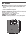
CONTROL BOARD OVERVIEW
1
2
3
4
5
6
7
8
9
10
11
SET OPEN Button: The SET OPEN button sets the OPEN limit. See Adjust Limits section.
SET CLOSE Button: The SET CLOSE button sets the CLOSE limit. See Adjust Limits section.
MOVE GATE Buttons: The MOVE GATE buttons will either open or close the gate when the operator is in Limit setting mode. See Adjust Limits section.
BATT FAIL:
• When AC power is OFF and battery voltage is critically low the gate will latch at a limit until AC power is restored or batteries voltage increases.
• Option select switch set to OPEN forces gate to automatically open and then latch at the OPEN limit until AC power is restored or battery
voltage increases.
• Option select switch set to CLOSE forces gate to latch at CLOSE limit if at CLOSE limit or on next CLOSE command until AC power restored or
battery voltage increases.
• Constant pressure on a hard command input overrides to open or close the gate.
• Critically low battery is less than 23 V
BIPART DELAY Switch: The LOCK/BIPART DELAY switch is used only for dual gates. See Bipart Delay section.
LEARN Button: The LEARN button is for programming remote controls and the network.
TIMER-TO-CLOSE dial: The TIMER-TO-CLOSE (TTC) dial can be set to automatically close the gate after a specified time period. The TTC is factory
set to OFF. If the TTC is set to the OFF position, then the gate will remain open until the operator receives another command from a control. Rotate the
TIMER-TO-CLOSE dial to the desired setting. The range is 0 to 180 seconds, 0 seconds is OFF.
NOTE: Any radio command, single button control, or CLOSE command on the control board prior to the TTC expiring will close the gate. The TTC is
reset by any signals from the open controls, loops, close edges, and close photoelectric sensors (IR’s).
REVERSAL FORCE dial: The REVERSAL FORCE dial adjusts the force. See Force Adjustment section.
TEST BUTTONS: The TEST BUTTONS will operate the gate (OPEN, STOP and CLOSE).
STATUS LEDs: The STATUS LEDs are diagnostic codes for the operator. See Status LED Chart in the Troubleshooting section.
Error Code Display: The error code display will show the operator type, firmware version, and error codes. The operator type will display as "LA"
followed by a "40" which indicates the operator type as LA400DC. The firmware version will show after the operator type, example "1.2".
1
2
3
4
5
6
8
7
11
10
28
9
OPERATION
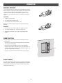
MANUAL RELEASE
In case of a power failure, the operator can be disengaged from the gate.
With an operator, the release action may sometimes feel stiff/jerky, which
is normal and has no effect on function. NOTE: It is normal for the
operator to run slow right after a disconnect or complete loss of AC/
battery power (the operator will need to run a complete open and close
cycle).
RELEASE
1. Insert the key into the lock.
2. Turn the key counter-clockwise 180°.
3. Turn the release lever counter-clockwise 180°.
Operator is in manual mode and the gate can be opened and closed
manually.
ENGAGE
1. Turn the release lever clockwise 180°. This engages the motor.
2. Turn the key clockwise 180°. This locks the release lever.
3. Remove the key and store in a safe place. The operator is now
engaged.
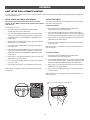
RESET BUTTON
The reset button is located on the side of the control box and serves
several functions:
•
Press the reset button to stop a moving gate during a normal open/
close cycle, like a stop button.
•
Press the reset button once while the gate is in open position to
disable the Timer-to-Close. The gate will stay in the open position. To
restart the Timer-to-Close either press the reset button or activate the
gate with a programmed remote control.
•
Reset Button
Press the reset button to shut off the alarm and reset the operator.
PARTY MODE
Press the reset button once while the gate is in open position to disable
the Timer-to-Close. The gate will stay in the open position. To restart the
Timer-to-Close either press the reset button or activate the gate with a
programmed remote control.
29
OPERATION
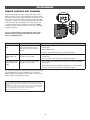
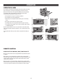
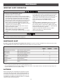
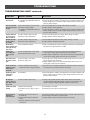
OPERATOR ALARM
If a contact sensor detects an obstruction twice consecutively the alarm
will sound (up to 5 minutes) and the operator will need to be reset.
When the inherent force of the operator (RPM/current sensor) detects
the following (twice consecutively) the alarm will sound (up to 5
minutes) and the operator will need to be reset:
A. The operator arm or gate is incorrectly installed.
B. The gate does not meet specifications.
A
B
C. Gate hinges are too tight or broken and the gate is not moving
freely.
D. The gate is moving and a car pushes the gate.
E. A foreign object is on the gate frame while the gate is moving.
F. The gate hits the driveway, curb or other, and gets stuck or bent in
an awkward position.
C
D
E
F
Remove any obstructions. Press the reset button to shut off the alarm
and reset the operator. After the operator is reset, normal functions will
resume.
The operator alarm will beep 3 times with a command if the battery is
low.
REMOTE CONTROL
SINGLE BUTTON CONTROL (SBC) FUNCTIONALITY
Once the remote control has been programmed the operator will operate
as follows:
When gate is in the closed position, activation of the remote control
button will open the gate. During the open cycle another activation of the
remote control will stop the gate and the next activation of the remote
control will close the gate.
When the gate is in the open position, activation of the remote control
button will close the gate. If the remote control is activated while the gate
is closing, the gate will stop and the next activation will open the gate.
30
ACCESSORY WIRING
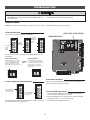
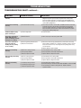
EXTERNAL CONTROL DEVICES
EXIT (2 Terminals)
This input is a soft open command (maintained switch does not override
external safeties and does not reset alarm condition). Used for exit probe,
telephone entry, external exit loop detector, or any device that would
command the gate to open.
•
(control board)
Exit
Com
Shadow
Opens a closing gate and holds open an open gate, if maintained,
pauses Timer-to-Close at OPEN limit.
Com
Interrupt
Com
SHADOW (2 Terminals)
This input is used for external shadow loop detector when loop is
positioned under the swing of the gate.
•
Holds open gate at open limit
•
Only active when the gate is at the OPEN limit, disregarded at all other
times
•
Pauses Timer-to-Close at OPEN limit
Interrupt Loop
INTERRUPT (2 Terminals)
Shadow Loop
This input is used for photoelectric sensors and external interrupt loop
detector when loop is on the outside of the gate.
•
Holds open gate at open limit
•
Stops and reverses a closing gate to open limit
•
Pauses Timer-to-Close at OPEN limit, activates quick close and
anti-tailgate features when enabled on the expansion board
Exit Loop
VEHICLE DETECTION DEVICES
Close Photoelectric Sensors
The same accessory inputs used for vehicle detection devices are also
used for entrapment protection devices (refer to step 9 of Installation).
The vehicle detection devices may be monitored or non-monitored, but
only ONE monitored device may be connected to each input, inclusive of
entrapment protection devices. Multiple non-monitored devices can be
wired to the same input. A monitored device sends a pulsed signal to the
operator so the operator is aware of the device. If the operator does not
receive the signal from the device indicating it is working properly, it will
not run in that direction.
Close Edge
Open Photoelectric Sensors
CLOSE EYES/INTERRUPT (2 Terminals)
The CLOSE EYES/INTERRUPT input is for photoelectric sensor vehicle
detection for the close direction. When an obstruction is sensed during
gate closing the gate will open to the full open position. This input will be
disregarded during gate opening and resets the Timer-to-Close.
CLOSE EDGE (2 Terminals)
The CLOSE EDGE input is for edge sensor vehicle detection for the close
direction. When an obstruction is sensed during gate closing the gate will
reverse for 4 seconds then stop, disengaging the Timer-to-Close. This
input will be disregarded during gate opening.
OPEN EYES/EDGE (2 Terminals)
The OPEN EYES/EDGE input is for photoelectric sensor or edge sensor
vehicle detection for the open direction. When an obstruction is sensed
during gate opening the gate will reverse for 4 seconds then stop. This
input will be disregarded during gate closing.
31
OR
Open Edge
ACCESSORY WIRING
LOCKS
(control board)
MAGLOCK (2 Terminals, N.C. and COM)
Maglock
Relay contact output, Normally - closed (N.C.) output for maglocks.
Relay activates prior to motor activation and during motor run. Relay is
off when motor is off.
NOTE: For AC power install a Siemens S10K30 MOV (Metal Oxide
Varistor) or equivalent. For DC power install a 1N4005 diode or
equivalent.
1N4005 diode
or equivalent.
SOLENOID (2 Terminals, N.O. and COM)
+
(not provided)
Siemens S10K30 MOV
(Metal Oxide Varistor)
or equivalent.
Normally - open (N.O.) output for solenoid locks
Relay activates prior to motor activation and during motor run. Relay is
off when motor is off.
(control board)
Solenoid Lock
NOTE: For AC power install a Siemens S10K30 MOV (Metal Oxide
Varistor) or equivalent. For DC power install a 1N4005 diode or
equivalent.
1N4005 diode
or equivalent.
+
(not provided)
MISCELLANEOUS WIRING
(main control board)
SINGLE BUTTON CONTROL (SBC) (2 Terminals)
Gate command sequence - Open, Stop, Close, Stop,...
Single Button Control Station
Soft open (maintained switch does not override external safeties and does
not reset alarm condition).
SBC
Com
Fire Dept
Com
FIRE DEPARTMENT OPEN INPUT (2 Terminals)
Fire Department
Acts as hard open.
Maintained input overrides (ignores) external safeties (photoelectric
sensor and edge), pauses Timer-to-Close momentary input logic as single
button control and safeties remain active, re-enables Timer-to-Close.
(main control board)
ACCESSORY POWER 24 VDC, MAX 500 mA (4 Terminals)
Accessory Power Switched
• SWITCHED: Switched ON with gate motion (stays on 5 seconds after
motion).
Com (-)
• UNSWITCHED: 24 Vdc voltage out to power accessories, always ON.
Com (-)
Acc Power +24 Vdc
Acc Power +24 Vdc
Accessory Power Unswitched
32
MAINTENANCE
IMPORTANT SAFETY INFORMATION
To reduce the risk of SEVERE INJURY or DEATH:
• READ AND FOLLOW ALL INSTRUCTIONS.
• ANY maintenance to the operator or in the area near the operator
MUST NOT be performed until disconnecting the electrical power (AC
or solar and battery) and locking-out the power via the operator
power switch. Upon completion of maintenance the area MUST be
cleared and secured, at that time the unit may be returned to service.
• Disconnect power at the fuse box BEFORE proceeding. Operator
MUST be properly grounded and connected in accordance with
national and local electrical codes. NOTE: The operator should be on
a separate fused line of adequate capacity.
• NEVER let children operate or play with gate controls. Keep the
remote control away from children.
• ALWAYS keep people and objects away from the gate. NO ONE
SHOULD CROSS THE PATH OF THE MOVING GATE.
• The entrance is for vehicles ONLY. Pedestrians MUST use separate
entrance.
• Test the gate operator monthly. The gate MUST reverse on contact
with a rigid object or reverse when an object activates the noncontact sensors. After adjusting the force or the limit of travel, retest
the gate operator. Failure to adjust and retest the gate operator
properly can increase the risk of INJURY or DEATH.
• Use the manual disconnect release ONLY when the gate is not
moving.
• KEEP GATES PROPERLY MAINTAINED. Read the owner’s manual.
Have a qualified service person make repairs to gate hardware.
• ALL maintenance MUST be performed by a LiftMaster professional.
• Activate gate ONLY when it can be seen clearly, is properly adjusted
and there are no obstructions to gate travel.
• To reduce the risk of FIRE or INJURY to persons use ONLY
LiftMaster part 29-NP712 for replacement batteries.
• SAVE THESE INSTRUCTIONS.
• ALWAYS wear protective gloves and eye protection when changing
the battery or working around the battery compartment.
MAINTENANCE CHART
Disconnect all power (AC and battery) to the operator before servicing. The operator's AC Power switch ONLY turns off AC power to the control
board and DOES NOT turn off battery power. ALWAYS disconnect the batteries to service the operator.
DESCRIPTION
TASK
Entrapment Protection Devices
Warning Signs
Manual Release
Gate
Check and test for proper operation
Make sure they are present
Check and test for proper operation
Inspect for wear or damage
Accessories
Electrical
Mounting Hardware
Operator
Batteries
Check all for proper operation
Inspect all wire connections
Check for tightness
Inspect for wear or damage
Replace
CHECK AT LEAST ONCE EVERY
MONTH
6 MONTHS
3 YEARS
X
X
X
X
X
X
X
X
X
NOTES:
• Severe or high cycle usage will require more frequent maintenance checks.
• It is suggested that while at the site voltage readings be taken at the operator. Using a digital voltmeter, verify that the incoming voltage to the
operator is within ten percent of the operator’s rating.
BATTERIES
Batteries will degrade over time depending on temperature and usage.
The operator alarm will beep 3 times with a command if the battery is
low. Batteries do not perform well in extremely cold temperatures. For
best performance, the batteries should be replaced every 3 years. Use
only LiftMaster part 29-NP712 for replacement batteries. The standard
control box comes with two 7AH batteries.
33
TROUBLESHOOTING
For continued protection against fire:
• Replace ONLY with fuse of same type and rating.
To protect against fire and electrocution:
• DISCONNECT power (AC or solar and battery) BEFORE installing or
servicing operator.
ERROR CODES
NOTE: When cycling or disconnecting power (ac/dc) to the control board, it is recommended that you unplug the J15 plug.
TO VIEW THE ERROR CODES
The error codes are shown on the error code display.
Press and
hold the
STOP
button...
OPEN, CLOSE, & STOP BUTTONS
ERROR CODE DISPLAY
...then press
and hold the
OPEN button
until “Er”
shows
...then press
and hold the
CLOSE button...
The operator will show the error sequence number followed by the error
code number:
ERROR SEQUENCE NUMBER
ERROR CODE NUMBER
The first number shown is the most
recent error (example: "01" shown
A SECOND
below). The display will show the
LATER....
sequence of errors that occurred
starting with "01" and going up to error
"20".
The second number shown after the
error sequence number is the error
code itself (31-99, example" "31" shown
below). Refer to the chart on the
following page for an explanation of
each error code.
TO EXIT ERROR CODE DISPLAY
Press and release the STOP button to exit. The error code display will
also time out after two minutes of inactivity.
TO SCROLL THROUGH THE SAVED ERROR CODES
Press the OPEN button
to cycle to the most
recent errors ("01").
TO RESET THE ERROR CODE HISTORY
1. Press and hold the STOP button for six seconds. The display will
show "Er" then "CL" alternately for six seconds.
2. Release the STOP button. The error history has now been reset and
the display will show "- -" until a new error occurs.
3. Press and release the STOP button to exit.
Press the CLOSE button
to cycle to the oldest
error (up to "20").
The operator will only keep track of up to 20 errors, then will start saving
over the oldest errors as new errors occur.
34
TROUBLESHOOTING
ERROR CODES continued...
Some errors are saved in the error code history and some are not. If an error is not saved it will briefly appear on the error code display as it occurs,
then disappear.
Code Error
31
32
33
34
35
Meaning
Solution
Control board has experienced an internal failure.
Disconnect all power, wait 15 seconds, then reconnect power (reboot).
If issue continues, replace control board.
Disengage then re-engage arm, check wiring and connections.
Disengage then re-engage arm, check wiring and connections.
Check the operator cable connections, then reprogram the limits.
Linear Drive Disengaged (Arm 1)
Linear Drive Disengaged (Arm 2)
Absolute Position Encoder Error, not getting
position information from encoder
Max-Run-Time Exceeded Error
Product ID Error
36
Product ID Failure
37
38
39
40
41
Hard Stop Limit (Arm 1)
Hard Stop Limit (Arm 2)
Battery overvoltage
Battery overcurrent
No battery at boot up
42
43
44
45
46
51
52
Loop Error - Failure or missing exit loop (SHORT
or OPEN - LiftMaster Plug-in Loop Detector only)
Loop Error - Failure or missing shadow loop
(SHORT or OPEN - LiftMaster Plug-in Loop
Detector only)
Loop Error - Failure or missing interrupt loop
(SHORT or OPEN - LiftMaster Plug-in Loop
Detector only)
Wireless edge battery low
Pass-point not detected (Arm 1)
Pass-point not detected (Arm 2)
Brownout occurred
53
Wireless Second Operator Communication Error
54
60
61
62
63
Minimum number of monitored entrapment
protection devices (one) not installed.
CLOSE EYE/INTERRUPT held more than 3 minutes
(main board)
CLOSE EDGE held more than 3 minutes (main
board)
OPEN EYE/EDGE held more than 3 minutes (main
board)
Check for an obstruction, then reprogram the limits.
Was the control board just replaced? If so, erase limits, enter limit
setup mode and set limits. If not, disconnect all power, wait 15
seconds, then reconnect power before changing product ID harness.
Unplug product ID harness then plug back in. Disconnect all power,
wait 15 seconds, then reconnect power before replacing product ID
harness.
Limit may be set too tightly against a non-resilient hard stop (re-adjust
limit). Operator may be at end of travel (re-adjust mounting).
Limit may be set too tightly against a non-resilient hard stop (re-adjust
limit). Operator may be at end of travel (re-adjust mounting).
Too much voltage on the battery. Check harness. Make sure you do
NOT have a 24V battery on a 12V system.
Possible short of the battery charge harness. Check harness. Make
sure you do NOT have a 12V battery on a 24V system.
Check battery connections and installation. Replace batteries if
depleted to less than 20V on a 24V system. Make sure you do NOT
have a single 12V battery on a 24V system.
Check loop wiring throughout connection. May be a short in the loop,
or an open connection in the loop.
Check loop wiring throughout connection. May be a short in the loop,
or an open connection in the loop.
Saved
NO
YES
YES
YES
YES
YES
YES
NO
NO
YES
YES
YES
YES
YES
Check loop wiring throughout connection. May be a short in the loop,
or an open connection in the loop.
YES
Replace batteries in wireless edge.
Check yellow pass-point wiring. If limits are not accurate, reprogram.
Rarely, may be standard operation.
Check yellow pass-point wiring. If limits are not accurate, reprogram.
Rarely, may be standard operation.
AC/DC board supply dipped below allowable level. Review power
supply and wiring. If rebooting, ensure enough time for discharge of
power to force a fresh boot.
Check the second operator for power. If OFF, restore power and try to
run the system. If powered, deactivate the wireless feature and then
re-learn the second operator.
Review monitored entrapment protection device connections.
YES
NO
Check CLOSE EYE/INTERRUPT input on main board; check for
alignment or obstruction.
Check CLOSE EDGE input on main board; check for alignment or
obstruction.
Check OPEN EYE/EDGE input on main board; check for alignment or
obstruction.
35
NO
YES
YES
NO
YES
YES
YES
TROUBLESHOOTING
ERROR CODES continued...
Some errors are saved in the error code history and some are not. If an error is not saved it will briefly appear on the error code display as it occurs,
then disappear.
Code Error
67
68
69
70
71
72
73
80
81
Meaning
Solution
Wireless edge triggered more than 3 minutes
Wireless edge loss of monitoring
Wireless edge triggered
Check wired input for wiring issue or obstruction.
Check wireless edge inputs.
IF an obstruction occurred, no action required. If an obstruction did
NOT occur, check inputs and wiring.
IF an obstruction occurred, no action required. If an obstruction did
NOT occur, check alignment, inputs, and wiring.
YES
YES
NO
IF an obstruction occurred, no action required. If an obstruction did
NOT occur, check alignment, inputs, and wiring.
IF an obstruction occurred, no action required. If an obstruction did
NOT occur, check alignment, inputs, and wiring.
IF an obstruction occurred, no action required. If an obstruction did
NOT occur, check alignment, inputs, and wiring.
NO
Check the connections between the main board and the secondary
operator
Check the connections between the main board and the secondary
operator.
Check for obstruction. If no obstruction, check that the operator arm is
engaged and free to move. Refer to Limit and Force Adjustment
section, and Obstruction Test.
Check for obstruction. If no obstruction, check that the operator arm is
engaged and free to move. Refer to Limit and Force Adjustment
section, and Obstruction Test.
Check for obstruction. If no obstruction, check the operator cable
wiring and that the operator arm is engaged and free to move. Replace
the operator arm if necessary.
Check for obstruction. If no obstruction, check the operator cable
wiring and that the operator arm is engaged and free to move. Replace
the operator arm if necessary.
No action required
YES
CLOSE EYE/INTERRUPT triggered, causing
reversal, preventing close, or resetting TTC (main
board)
CLOSE EDGE triggered, causing reversal,
preventing close, or cancelling TTC (main board)
OPEN EYE/EDGE triggered, causing reversal or
preventing opening (main board)
CLOSE EYE/INTERRUPT triggered, causing
reversal, preventing close, or resetting TTC
(expansion board)
Close input (EYE/EDGE) communication fault
(secondary control box)
Open input (EYE/EDGE) communication fault
(secondary control box)
Force reversal (Arm 1)
91
Force reversal (Arm 2)
92
RPM / STALL Reversal (Arm 1)
93
RPM / STALL Reversal (Arm 2)
94
99
Normal Operation
36
Saved
NO
NO
NO
YES
YES
YES
YES
YES
YES
TROUBLESHOOTING
CONTROL BOARD LEDS
STATUS LEDS
INPUT
POWER
OFF
ON
OFF
BATT
CHARGING ON
OFF
TIMER
ON
MEDIUM BLINK (1
blink per second)
FAST BLINK (2 blinks
per second)
FASTEST BLINK (8
blinks per second)
OFF
GATE
MOVING
ON
MEDIUM BLINK (1
blink per second)
FASTEST BLINK (8
blinks per second)
BATT LOW OFF
ON
BLINK (1 blink per
second)
ACC PWR OFF
OVLD
ON
INPUT LEDS
OFF state
AC charger or Solar power
available
Not charging
Three stage battery charging
The timer is disabled
The timer is enabled
The timer is running
SBC INPUT
FIRE DEPT
INPUT
EXIT
The timer is paused
SHADOW
The timer is cancelled
The gate is stopped
The gate is opening or closing
Operator is in E1 (single
entrapment)
The operator is in E2 (double
entrapment)
No battery error
Battery low
Battery critically low
ON
Input active
BLINK
Input active on other operator
OFF
Input inactive
ON
Input active
BLINK
Input active on other operator
OFF
Input inactive
ON
Input active
BLINK
Input active on other operator
OFF
Input inactive
Input active
BLINK
Input active on other operator
CLOSE EYES/
INTERRUPT
OFF
Input inactive
ON
Input active
BLINK
Input active on other operator
CLOSE EDGE
OFF
Input inactive
Accessory overload protector
opened
LOCK
STATUS LEDS
ON
Input active
BLINK
Input active on other operator
OFF
Input inactive
ON
Input active
BLINK
Input active on other operator
OFF
Input inactive
ON
Input active
BLINK
Input active on other operator
INPUT LEDS
37
Input inactive
ON
OPEN EYES/
EDGE
OFF state
OFF
TROUBLESHOOTING
TROUBLESHOOTING CHART
SYMPTOM
POSSIBLE CAUSES
Operator does not
run and error code
display not on.
a) No power to control board
b) Open fuse
c) If on battery power only, low or dead batteries
d) Defective control board
a) Reset button is stuck
b) Stop button active or jumper not in place
for stop circuit
c) If on battery power only, low or dead batteries
d) Open or Close input active
e) Entrapment Protection Device active
f) Vehicle loop detector or probe active
g) Defective control board
a) Arm does not extend or retract enough
during travel
b) Arm is interfering with mounting bracket
c) Gate is too difficult to move
Gate opens, but
will not close with
transmitter or
Timer-to-Close.
a) Open control active
b) Vehicle loop detector active
c) Loss of AC power with AC FAIL set to
OPEN
d) Low battery with LOW BATT set to OPEN
e Fire Dept input active
f) Timer-to-Close not set
g) Close Entrapment Protection Device active
SOLUTIONS
a) Check AC and battery power
b) Check fuses
c) Charge batteries by AC or solar power or replace batteries
d) Replace defective control board
Control board
a) Check Reset button
powers up, but
b) Check Stop button is not “stuck on”, or verify that the stop button is a
motor does not
normally closed circuit, or put a jumper on the stop circuit.
run.
c) Charges batteries by AC or solar power or replace batteries
d) Check all Open and Close inputs for a “stuck on” input
e) Check all Entrapment Protection Device inputs for a “stuck on” sensor
f) Check all vehicle detector inputs for a “stuck on” detector
g) Replace defective control board
Arm moves, but
a) Disengage the arm and ensure arm moves freely
cannot set correct
b) Examine the hinge point where the arm mounts to the gate post. Make
limits.
sure that the arm housing does not hit or interfere with the gate post or
mounting bracket. Correct as necessary.
c) Disconnect arm from gate and move gate manually. Gate must move easily
and freely through its entire range, limit-to-limit. Repair gate as needed.
Gate does not fully a) Arm does not extend or retract enough
a) Disengage the arm and ensure arm moves freely
open or fully close
during travel
b) Examine the hinge point where the arm mounts to the gate post. Make
when setting
b) Arm is interfering with mounting bracket
sure that the arm housing does not hit or interfere with the gate post or
limits.
mounting bracket. Correct as necessary.
c) Gate is too difficult to move
c) Remove arm from gate and move gate manually. Gate must move easily
and freely through its entire range, limit-to-limit. Repair gate as needed.
Operator does not a) Check Open and Close command input LEDs a) Check all Open and Close inputs for a “stuck on” input
respond to a wired b) Stop button is active
b) Check Stop button is not “stuck on”
control/command
c) Reset button is stuck
c) Check Reset button
(example: Open,
d) If on battery power only, low or dead batteries d) Charges batteries by AC or solar power or replace batteries
Close, SBC, etc.)
e) Entrapment Protection Device active
e) Check all Entrapment Protection Device inputs for a “stuck on” sensor
f) Vehicle loop detector or vehicle probe active
f) Check all vehicle detector inputs for a “stuck on” detector
Operator does not a) Check XMITTER LED when wireless
a) Activate wireless control and check XMITTER LED is on. Re-learn wireless
respond to a
control is active
control/transmitter to control board. Replace wireless control as needed.
wireless control or b) Stop button is active
b) Check Stop button is not “stuck on”
transmitter
c) Reset button is stuck
c) Check Reset button
d) Poor radio reception
d) Check if similar wired control operates correctly. Check if wireless controls
works properly when within a few feet of operator. Check operator’s
antenna and antenna wire. Check other wireless controls or devices.
Gate stops during
a) Control (Open, Close) becoming active
a) Check all Open and Close inputs for an active input
travel and reverses b) Vehicle loop detector active
b) Check all vehicle detector inputs for an active detector
immediately.
c) Low battery voltage
c) Battery voltage must be 23.0 Vdc or higher. Charge batteries by AC or
solar power or replace batteries
a) Check all Open inputs for an active input
b) Check all vehicle detector inputs for an active detector
c) Check AC power and AC Fail option setting
d) Check if AC power is available. If no AC power, then running on batteries
and battery voltage must be 23.0 Vdc or higher. Charge batteries by AC or
solar power or replace batteries.
e) Check Fire Dept input
f) Check Timer-to-Close (TTC) setting
g) Check all Entrapment Protection Device inputs for an active sensor
38
TROUBLESHOOTING
TROUBLESHOOTING CHART continued...
SYMPTOM
POSSIBLE CAUSES
SOLUTIONS
Gate closes, but
will not open.
a) Vehicle loop detector active
b) Low battery with LOW BATT option set
to CLOSE
a) Check all vehicle detector inputs for an active detector
b) Check if AC power is available. If no AC power, then running on batteries and
battery voltage must be 23.0 Vdc or higher. Charge batteries by AC or solar
power or replace batteries
Exit loop activation
does not cause gate
to open.
a) Exit vehicle detector setup incorrectly
b) Defective Exit loop detector
c) Low battery with LOW BATT option set
to CLOSE
a) Review Exit loop detector settings. Adjust settings as needed.
b) Replace defective Exit loop detector.
c) Check if AC power is available. If no AC power, then running on batteries and
battery voltage must be 23.0 Vdc or higher. Charge batteries by AC or solar
power or replace batteries.
Interrupt loop does
not cause gate to
stop and reverse.
a) Vehicle detector setup incorrectly
b) Defective vehicle loop detector
a) Review Interrupt loop detector settings. Adjust settings as needed.
b) Replace defective Interrupt loop detector.
Shadow loop does
not keep gate at
open limit.
a) Vehicle detector setup incorrectly
b) Defective vehicle loop detector
a) Review Shadow loop detector settings. Adjust settings as needed.
b) Replace defective Shadow loop detector.
Obstruction in
a) Force adjustment needed
gate's path does not
cause gate to stop
and reverse
a) Refer to the Adjustment section to conduct the obstruction test and perform
the proper force adjustment that is needed.
Photoelectric
sensor does not
stop or reverse
gate.
a) Incorrect photoelectric sensor wiring
b) Defective photoelectric sensor
a) Check photoelectric sensor wiring. Retest that obstructing photoelectric
sensor causes moving gate to stop, and may reverse direction.
b) Replace defective photoelectric sensor. Retest that obstructing photoelectric
sensor causes moving gate to stop, and may reverse direction.
Edge Sensor does
not stop or reverse
gate.
a) Incorrect edge sensor wiring
b) Defective edge sensor
a) Check edge sensor wiring. Retest that activating edge sensor causes moving
gate to stop and reverse direction.
b) Replace defective edge sensor. Retest that activating edge sensor causes
moving gate to stop and reverse direction.
Alarm sounds for 5
minutes or alarm
sounds with a
command.
a) Double entrapment occurred (two
obstructions within a single activation)
a) Check for cause of entrapment (obstruction) detection and correct. Press the
reset button to shut off alarm and reset the operator.
Alarm beeps three
times with a
command.
a) Low battery
a) Check if AC power is available. If no AC power, then running on batteries and
battery voltage must be 23.0 Vdc or higher. Charge batteries by AC or solar
power or replace batteries
On dual-gate
system, incorrect
gate opens first or
closes first.
a) Incorrect Bipart switch setting
a) Change setting of both operator’s Bipart switch settings. One operator
should have Bipart switch ON (operator that opens second) and the other
operator should have Bipart switch OFF (operator that opens first)
Alarm beeps when
running.
a) Expansion board setting
b) Constant pressure to open or close is
given
a) Pre-warning is set to "ON"
b) Constant pressure to open or closed is given
Expansion board
function not
controlling gate.
a) Defective main board to expansion
board wiring
b) Incorrect input wiring to expansion
board
c) Defective expansion board or defective
main board
a) Check main board to expansion board wiring. If required, replace wire cable.
b) Check wiring to all inputs on expansion board.
c) Replace defective expansion board or defective main board
39
TROUBLESHOOTING
TROUBLESHOOTING CHART continued...
SYMPTOM
POSSIBLE CAUSES
SOLUTIONS
Maglock not working
correctly.
a) Maglock wired incorrectly
a) Check that Maglock is wired to N.C. and COM terminals. Check that
Maglock has power (do not power maglock from control board
accessory power terminals). If shorting lock’s NO and COM wires
does not activate Maglock, then replace Maglock or Maglock wiring
(refer to Wiring Diagrams).
Solenoid lock not working
correctly.
a) Solenoid wired incorrectly
a) Check that Solenoid is wired to N.O. and COM terminals. Check that
Solenoid has power (do not power solenoid from control board
accessory power terminals). If shorting lock’s NC and COM wires
does not activate Solenoid, then replace Solenoid lock or Solenoid
wiring (refer to Wiring Diagrams).
Switched (SW) Accessory
power remaining on.
a) In limit setup mode
a) Learn the limits
Accessories connected to
a) Normal behavior
Switch (SW) Accessory
power not working correctly,
turning off, or resetting.
a) Move accessory to accessory power "ON"
Accessories connected to
Accessory power not
working correctly, turning
off, or resetting.
a) Accessory power protector active
b) Defective control board
a) Disconnect all accessory powered devices and measure accessory
power voltage (should be 23 – 30 Vdc). If voltage is correct, connect
accessories one at a time, measuring accessory voltage after every
new connection.
b) Replace defective control board
Quick Close not working
correctly.
a) Quick Close setting incorrect
b) Interrupt loop detector
c) Defective Expansion board
a) Check that Quick Close setting is ON
b) Check operation of Interrupt Loop detector
c) Replace defective Expansion board
Anti-Tailgating not working
correctly.
a) Anti-Tail setting incorrect
b) Interrupt loop detector
c) Defective Expansion board
a) Check that Anti-Tail setting is ON
b) Check operation of Interrupt Loop detector
c) Replace defective Expansion board
AUX Relay not working
correctly.
a) AUX Relay setting incorrect
a) Check AUX Relay switches settings
b) Check that wiring is connected to either N.O. and COM or to N.C. and COM.
c) Set AUX Relay to another setting and test. Replace defective
expansion board.
b) AUX Relay wiring incorrect
c) Defective Expansion board
40
APPENDIX
BRACKET TYPES
PULL-TO-OPEN
Right-Hand Gate
Left-Hand Gate
PUSH-TO-OPEN
Left-Hand Gate
Right-Hand Gate
41
APPENDIX
STEP 10
SOLAR PANEL(S)
SOLAR PANELS ARE NOT PROVIDED. SEE ACCESSORIES.
33AH Battery Requirements:
7AH Battery Requirements:
• Large Metal Control Box for Solar Applications
• Standard Control Box for Solar Applications (Model LA400CONTDC)
(Model XLSOLARCONTDC)
• A minimum of two 10W solar panels in series (Model
• A minimum of two 10W solar panels in series
SOLPNL10W12V)
(Model SOLPNL10W12V)
• A maximum of six 10W solar panels (Model SOLPNL10W12V).
• A maximum of six 10W solar panels (Model SOLPNL10W12V).
Configuration of three sets of two 10W paralleled panels put in series.
Configuration of three sets of two 10W paralleled panels put in series.
• Two 7AH batteries (29-NP712)
• Two 33AH Batteries (Model A12330SGLPK)
• Solar Battery Harness (Model K94-37236)
• Solar Battery Harness (Model K94-37236)
• Battery Tray (Model K10-36183)
Disconnect the expansion board if it is not in use to improve performance. We recommend LiftMaster low power draw accessories to minimize power
draw, refer to accessory page. Use the tables below to see performance trade-offs. NOTE: Input solar power is 24 Vdc at 60 watts maximum.
The solar panel(s) must be located in an open area clear of obstructions and shading for the entire day. The gate operator is not supported in northern
climates where temperatures reach below -4˚F. This is due to cold weather and a reduced number of hours of sunlight during the winter months. Cycle
rate may vary from solar chart for areas that reach below 32˚F. Solar panels should be cleaned on a regular basis for best performance to ensure
proper operation.
SOLAR USAGE GUIDE
The LA400DC has best in class solar performance due to highly efficient electronics that draw very little power while the gate is not in use (standby).
Typical System Standby Battery Current Consumption (mA)
2.7 mA
+1 mA
+2.4 mA
System Configuration
Main control board draw with no remote controls programmed
Low band radio receiver active (one or more wireless transmitters learned)
High band radio active (MyQ device programmed)
+11.1 mA
Expansion board
+3.8 mA
Per loop detector (up to 3 loop detectors can be plugged into the expansion board)
This low current draw drastically increases the number of days the operator can remain in standby. To determine your system’s performance,
reference the above table and determine how many milliamps (mA) your system will draw from the batteries.
EXAMPLE 1: A system with only a main control board and one or more hand held remote controls programmed will draw 3.7 mA from the batteries
while the system is in standby (2.7 mA + 1 mA = 3.7 mA).
EXAMPLE 2: A system with only a main control board, one or more hand held remote controls programmed, and 20 mA of external accessories
connected to the main control board's accessory power output will draw 23.7 mA from the batteries while the system is in standby
(2.7 mA + 1 mA + 20 mA = 23.7 mA).
EXAMPLE 3: A system with a main control board, expansion board, two loop detectors, and one or more hand held remote controls programmed will
draw 18 mA from the batteries while the system is in standby (2.7 mA + 11.1 mA + 3.8 mA*2 +1 = 18.6 mA).
Operator performance with no sun or loss of AC power
BATTERY
CURRENT
DRAW (mA)
SYSTEM CONFIGURATION
DAYS OF STANDBY
SINGLE GATE CYCLES ON BATTERY
DUAL GATE CYCLES ON BATTERY
7AH batteries
33AH batteries
7AH batteries
33AH batteries
7AH batteries
33AH batteries
2.7
main control board only
133
180
400
3623
330
1752
3.7
remote controls programmed
97
180
400
3622
330
1752
6.1
remote controls and MyQ programmed
59
180
400
3622
330
1752
14.8
remote controls and expansion board
24
105
400
3621
330
1752
18.6
remote controls, expansion board, and one loop detector
19
84
400
3620
330
1751
26.2
remote controls, expansion board, and three loop detectors
14
60
400
3619
329
1751
30
12
52
400
3619
329
1751
40
9
39
400
3618
329
1750
60
6
26
400
3615
328
1749
100
4
16
400
3610
326
1746
2
1
1
8
5
3
400
400
400
3596
3583
3557
322
318
311
1740
1734
1721
200
300
500
All numbers are estimates. Actual results may vary.
42
APPENDIX
STEP 10 continued...
SOLAR ZONES
3
SOLAR PANEL(S)
NOT AVAILABLE
NOT AVAILABLE
SOLAR USAGE GUIDE
3
2
1
2
1
1
SOLAR GATE CYCLES PER DAY (SINGLE GATE)
BATTERY
CURRENT
DRAW (mA)
10W SOLAR PANEL
20W SOLAR PANEL
40W SOLAR PANEL
60W SOLAR PANEL
ZONE 1
(6 Hrs sunlight/day)
ZONE 2
(4 Hrs Sunlight/day)
ZONE 3
(2 Hrs Sunlight/day)
7AH batteries
33AH batteries
7AH batteries
33AH batteries
7AH batteries
33AH batteries
5
81
87
47
51
18
19
15
68
74
36
39
n/a
n/a
20
61
68
30
34
n/a
n/a
40
37
43
n/a
13
n/a
n/a
n/a
60
16
21
n/a
n/a
n/a
5
100
100
100
100
42
50
15
100
100
92
100
31
38
20
100
100
85
100
25
33
50
100
100
47
63
n/a
n/a
100
46
70
n/a
n/a
n/a
n/a
5
15
20
100
100
100
100
100
100
100
100
100
100
100
100
65
100
100
100
100
83
70
63
n/a
100
100
97
n/a
200
42
100
n/a
11
n/a
n/a
5
15
20
100
250
100
100
100
100
37
100
100
100
100
100
100
100
100
100
n/a
100
100
100
100
61
100
90
83
n/a
n/a
100
100
100
55
n/a
SOLAR GATE CYCLES PER DAY (DUAL GATE)
BATTERY
CURRENT
DRAW (mA)
10W SOLAR PANEL
20W SOLAR PANEL
40W SOLAR PANEL
60W SOLAR PANEL
ZONE 1
(6 Hrs sunlight/day)
ZONE 2
(4 Hrs Sunlight/day)
ZONE 3
(2 Hrs Sunlight/day)
7AH batteries
33AH batteries
7AH batteries
33AH batteries
7AH batteries
33AH batteries
5
35
37
20
22
n/a
n/a
15
29
32
15
17
n/a
n/a
20
26
29
13
14
n/a
n/a
40
16
18
n/a
n/a
n/a
n/a
60
n/a
n/a
n/a
n/a
n/a
n/a
5
76
89
45
53
18
21
15
69
82
39
47
13
16
20
66
79
36
44
11
14
50
48
59
20
27
n/a
n/a
100
20
30
n/a
n/a
n/a
n/a
5
15
20
100
100
100
100
77
100
100
100
100
86
79
76
28
100
100
100
58
35
30
27
n/a
51
45
42
n/a
200
18
63
n/a
n/a
n/a
n/a
5
15
20
100
250
100
100
100
100
16
100
100
100
100
100
100
100
96
45
n/a
100
100
100
100
26
44
38
36
n/a
n/a
81
74
71
24
n/a
All numbers are estimates. Actual results may vary.
43
APPENDIX
LIMIT SETUP WITH A REMOTE CONTROL
To set the limits using a remote control, first you will need a 3-button remote control that has been programmed for OPEN, CLOSE, and STOP. Refer
to the Programming section.
INITIAL LIMITS AND FORCE ADJUSTMENT
ADJUST THE LIMITS
For dual gate applications the limits will have to be set for each
operator. The gate MUST be attached to the operator before setting the
limits and force.
If the limits have already been set the operator will exit the limit setting
mode after resetting each limit.
Set the Close Limit Only
Ensure the gate is closed.
1.
Press and release the SET OPEN and SET CLOSE buttons
simultaneously to enter limit setting mode.
2.
Press and hold the OPEN or CLOSE button on the remote control
until the gate reaches the desired open position. The gate can be
jogged back and forth using the OPEN and CLOSE buttons on the
remote control.
3.
Once the gate is in the desired open position, press and release the
STOP button on the remote control.
4.
Press and release the OPEN button on the remote control again to
set the open limit.
5.
Press and hold the CLOSE or OPEN button on the remote control
until the gate reaches the desired close position. The gate can be
jogged back and forth using the OPEN and CLOSE buttons on the
remote control.
1.
Press and release the SET OPEN and SET CLOSE buttons
simultaneously to enter limit setting mode.
2.
Press and hold the CLOSE button on the remote control until the
gate reaches the desired close position. The gate can be jogged back
and forth using the OPEN and CLOSE buttons on the remote control.
3.
Once the gate is in the desired close position, press and release the
STOP button on the remote control.
4.
Press and release the CLOSE button on the remote control again to
set the close limit.
When the close limit is set properly the operator will automatically exit
limit setting mode.
Set the Open Limit Only
1.
Press and release the SET OPEN and SET CLOSE buttons
simultaneously to enter limit setting mode.
2.
Press and hold the OPEN button on the remote control until the gate
reaches the desired open position. The gate can be jogged back and
forth using the OPEN and CLOSE buttons on the remote control.
Cycle the gate open and close. This automatically sets the force.
3.
Once the gate is in the desired open position, press and release the
STOP button on the remote control.
When limits are set properly the operator will automatically exit limit
setting mode.
4.
Press and release the OPEN button on the remote control again to
set the open limit.
6.
Once the gate is in the desired close position, press and release the
STOP button on the remote control.
7.
Press and release the CLOSE button on the remote control again to
set the close limit.
8.
When the open limit is set properly the operator will automatically exit
limit setting mode.
3-Button Remote Control programmed for OPEN, CLOSE, and
STOP
SET OPEN SET CLOSE
PRESS &
RELEASE
47
REPAIR PARTS
CONTROL BOX
1
ITEM
PART NUMBER
DESCRIPTION
1
K74-36798-2
Standard Plastic Control Box Only
2
K94-36408-2
Reset Switch with Product ID
3
K94-36411
Piezo Alarm
4
K75-36635
Control Board Bracket
5
K1D8052-1CC
Control Board
6
K76-36296-1
Outlet
7
APOW3
Transformer
8
K74-30762
NOT SHOWN
K94-36274-1
K77-36541
LA400CONTDC
K74-30941
Batteries (2)
2
4
7AH Battery Harness
3
Antenna
Standard Plastic Control Box (with
control board)
ATC Fuse Kit Includes 20 Amp (1),
15 Amp (2)
8
5
6
7
GATE OPERATOR ARM
3
4
2
1
5
48
ITEM
PART NUMBER
DESCRIPTION
1
LA400
Primary Arm
2
41ASWG-442SA
Release Lever
3
41ASWG-438SA
Motor with Limit Switch Harness
4
41ASWG-0014SA
Rear Connector
5
41ASWG-489
NOT SHOWN
Cable 24 V with Connector
41ASWG-0119
Release Key
K77-19130
Hardware Bag
Complete with: Gate bracket, post
bracket, pull-to-open bracket and
hardware
WIRING DIAGRAM
STANDARD CONTROL BOX
To protect against fire and electrocution:
• DISCONNECT power and battery BEFORE installing or servicing
LA400
WIRING DIAGRAM PLASTIC E-BOX
operator.
47-???????
For continued protection against fire:
ECN:
• Replace
ONLY with fuse of same type and rating.
Reference:
06-36928
11/19/13
Antenna
Coaxial Antenna Cable
-
+
Red
-
12V 7AH Battery
+
-
+
-
12V 7AH Battery
+
Black
Photoelectric Sensors
-
Two 12V Solar Panels in Series
+
Photoelectric Sensors
-
+
-
+
Red
To J15
Blocking
Diode
Black
Attach to Metal Chassis
Black
Red
Primary Operator
Yellow
Accessory
Power Outlets
Attach to Outlet
Metal Chassis With
a Single Screw
Secondary Operator
Red
L
GND
White
White
Input Power Connection
Black
Piezo Alarm
Transformer
(Optional)
Reset Switch
N
-
+
49
Edge
-
Edge
+
Field Wiring
+
-
ACCESSORIES
MISCELLANEOUS
ENTRAPMENT PROTECTION DEVICES
REMOTE ANTENNA EXTENSION KIT
The remote antenna extension kit allows the
antenna to be remotely installed.
Model 86LM
PHOTOELECTRIC SENSORS (MONITORED,
NON-CONTACT)
The photoelectric sensors are designed to detect an
obstacle in the path of the electronic beam and
stop the operator. Includes mounting brackets.
Models CPS-UN4 and CPS-RPEN4GM (LiftMaster
low power accessory)
WIRELESS ACCESS CONTROL RECEIVER
Access control receiver for up to 450 remote
controls.
Model STAR450-315
VEHICLE DETECTION DEVICES
PHOTOELECTRIC SENSORS (NON-MONITORED,
NON-CONTACT)
The photoelectric sensors are designed to detect an
obstacle in the path of the electronic beam and
stop the operator. Includes mounting brackets.
Models AOMRON E3K-R10K4-NR (retro-reflective)
and RETROAB 60-2728 (retro-reflective)
PLUG-IN LOOP DETECTOR
Low power. Conveniently plugs into existing control
board.
Model LOOPDETLM
OPEN
LOOP DETECTOR
Low power loop detectors mounted and wired
separately inside control box. LiftMaster low power
accessory.
Model LD7LP
SENSING EDGE (2-WIRE, NON-MONITORED,
CONTACT)
Sensing edges can detect an obstacle upon contact
and stop the operator.
Models G65MG0204, G65MG0205, G65MGR205,
and G65MGS205
SENSING EDGE CHANNEL
Mounting channel for all MG020 type edges.
Model G65ME120C5
VEHICLE SENSING PROBE
The vehicle sensing probe is buried in the ground
and can detect a car as it approaches and will then
open the gate.
Model CP3
PUSH-TO-OPEN BRACKET
Used to allow the gate operator to push the gate
open.
Model 50-19503
REMOTE CONTROLS
Chamberlain offers a variety of LiftMaster remote controls to satisfy your
application needs. Single-button to 4-button, visor or key chain. The
following remote controls are compatible with operators manufactured by
Chamberlain after 1993. Contact your authorized LiftMaster dealer for
additional details and options.
SOLENOID GATE LOCK
The automatic gate lock is a solenoid-driven lock
that automatically unlocks when the gate is open
and locks when the gate is closed. Can be mounted
onto a gate or post. Can be released in case of
emergency.
Model GC824-12 (12/24 Vac/dc)
3-BUTTON REMOTE CONTROL
The 3-button remote control can be programmed to
control the operator. Includes visor clip.
Model 893MAX
MAGNETIC GATE LOCK
Outdoor magnetic lock, transformer, junction box,
mounting plate and hardware. Not for use with
Solar Applications. Must be powered separately.
Model MG1300 (12/24 Vdc)
3-BUTTON MINI-REMOTE CONTROL
The 3-button remote control can be programmed to
control the operator. Includes key ring and
fastening strip.
Model 890MAX
TRANSFORMER
Model APOW3
SOLAR PANEL KIT - 10 WATT
This kit is to replace or add a solar panel to the
operator application. Up to four solar panels can be
connected to the operator. Requires a 33AH battery
harness.
Model SOLPNL10W12V (requires 2 minimum)
KEYLESS ENTRY
Enables homeowner to operate gate operator from
outside by entering a 4-digit code on a specially
designed keypad.
Model 877MAX
EXPANSION BOARD
Model K1D8080-1CC
50
ACCESSORIES
33AH BATTERIES
Upgrade 33 AMP-Hour Battery, 12 Vdc. Ideal for solar
applications and extended battery backup. For use
with Large Metal Control Box ONLY.
Model A12330SGLPK
BATTERY TRAY
Required for 33AH applications.
Model K10-36183)
SOLAR BATTERY HARNESS
Required for 33AH applications.
Model K94-37236
BATTERIES
Gate access system batteries replace or upgrade the gate operator
batteries. Two identical 12 Vdc batteries are required for each gate
operator. Do not mix 7AH and 33AH batteries within a gate operator.
7AH BATTERIES
Standard 7 AMP-Hour Battery, 12 Vdc, to replace
original batteries provided with operator. Reuse
existing harnesses.
Model 29-NP712
WARRANTY
LIFTMASTER TWO YEAR LIMITED WARRANTY
The Chamberlain Group, Inc. warrants to the first purchaser of this product, for the structure in which this product is originally installed, that it is free
from defect in materials and/or workmanship for a period of TWO years from the date of purchase. The proper operation of this product is dependent
on your compliance with the instructions regarding installation, operation, maintenance and testing. Failure to comply strictly with those instructions
will void this limited warranty in its entirety.
If, during the limited warranty period, this product appears to contain a defect covered by this limited warranty, call 1-800-528-2806, toll free, before
dismantling this product. Then send this product, pre-paid and insured, to our service center for warranty repair. You will be advised of shipping
instructions when you call. Please include a brief description of the problem and a dated proof-of purchase receipt with any product returned for
warranty repair. Products returned to Seller for warranty repair, which upon receipt by Seller are confirmed to be defective and covered by this limited
warranty, will be repaired or replaced (at Seller’s sole option) at no cost to you and returned pre-paid. Defective parts will be repaired or replaced with
new or factory-rebuilt parts at Seller’s sole option.
ALL IMPLIED WARRANTIES FOR THE PRODUCT, INCLUDING BUT NOT LIMITED TO ANY IMPLIED WARRANTIES OF MERCHANTABILITY AND
FITNESS FOR A PARTICULAR PURPOSE, ARE LIMITED IN DURATION TO THE TWO YEAR LIMITED WARRANTY PERIOD SET FORTH ABOVE, AND
NO IMPLIED WARRANTIES WILL EXIST OR APPLY AFTER SUCH PERIOD. Some states do not allow limitations on how long an implied warranty
lasts, so the above limitation may not apply to you. THIS LIMITED WARRANTY DOES NOT COVER NON-DEFECT DAMAGE, DAMAGE CAUSED BY
IMPROPER INSTALLATION, OPERATION OR CARE (INCLUDING, BUT NOT LIMITED TO ABUSE, MISUSE, FAILURE TO PROVIDE REASONABLE AND
NECESSARY MAINTENANCE, UNAUTHORIZED REPAIRS OR ANY ALTERATIONS TO THIS PRODUCT), LABOR CHARGES FOR REINSTALLING A
REPAIRED OR REPLACED UNIT, OR REPLACEMENT OF BATTERIES.
THIS LIMITED WARRANTY DOES NOT COVER ANY PROBLEMS WITH, OR RELATING TO, THE GATE OR GATE HARDWARE, INCLUDING BUT NOT
LIMITED TO THE GATE SPRINGS, GATE ROLLERS, GATE ALIGNMENT OR HINGES. THIS LIMITED WARRANTY ALSO DOES NOT COVER ANY
PROBLEMS CAUSED BY INTERFERENCE. ANY SERVICE CALL THAT DETERMINES THE PROBLEM HAS BEEN CAUSED BY ANY OF THESE ITEMS
COULD RESULT IN A FEE TO YOU.
UNDER NO CIRCUMSTANCES SHALL SELLER BE LIABLE FOR CONSEQUENTIAL, INCIDENTAL OR SPECIAL DAMAGES ARISING IN CONNECTION
WITH USE, OR INABILITY TO USE, THIS PRODUCT. IN NO EVENT SHALL SELLER’S LIABILITY FOR BREACH OF WARRANTY, BREACH OF
CONTRACT, NEGLIGENCE OR STRICT LIABILITY EXCEED THE COST OF THE PRODUCT COVERED HEREBY. NO PERSON IS AUTHORIZED TO
ASSUME FOR US ANY OTHER LIABILITY IN CONNECTION WITH THE SALE OF THIS PRODUCT.
Some states do not allow the exclusion or limitation of consequential, incidental or special damages, so the above limitation or exclusion may not
apply to you. This limited warranty gives you specific legal rights, and you may also have other rights which vary from state to state.
51
1
2
3
4
5
6
7
TEMPLATE FOR POST BRACKET MOUNTING
7
6
5
4
3
52
2
1
845 Larch Avenue
Elmhurst, Illinois 60126-1196
www.liftmaster.com
01-37070B
© 2014, The Chamberlain Group, Inc. – All Rights Reserved