1
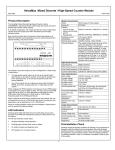
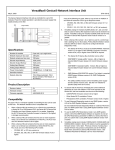
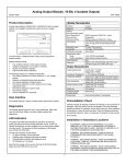
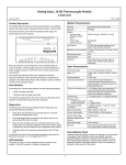
VersaMax Mixed Discrete / High-Speed Counter Module IC200MDD841 May 2011 GFK-1561H Product Description Module Characteristics Points 20 DC inputs & 12 DC outputs Module ID FFFF9801 Isolation: User I/O to logic 250VAC continuous, 1500VAC for 1 minute (optical) and to frame ground 250VAC continuous, 1500VAC for 1 minute Point to point Backplane current 3.3V output: 130mA, consumption 5V output: 30mA External power supply +24VDC nominal, +18 to +30VDC The VersaMax Mixed Discrete High-Speed Counter (HSC) module, IC200MDD841, has twenty 24VDC positive-logic type inputs and twelve positive-logic 24VDC 0.5Amp outputs. In its default configuration, the module provides four Type A high-speed counter inputs and outputs plus twelve standard inputs and eight standard outputs. Each counter provides direct processing of rapid pulse signals up to 80 KHz for industrial control applications such as velocity measurement, material handling, and process control. Thermal Derating FLD PWR Q/I 1 2 3 4 5 6 7 8 OK 9 10 11 12 17 18 19 20 HSC/PWM/PT 24VDC IN 20PT OUT .5A 12PT 1 2 3 4 5 6 7 8 9 10 11 12 13 14 15 16 1234567 814 I The number of points that can be on at the same time depends on the surrounding air temperature, voltage, and the type of carrier on which the module is installed. To meet thermal specifications, the module must be installed on a horizontal DIN rail. There is no thermal derating at 24VDC for surrounding temperatures up to 42°C, or at 30VDC for temperatures up to 26°C. For derating curves at higher temperatures, see the I/O Modules User’s Manual. High Speed Channels Input frequency 80 KHz maximum PWM Output frequency 2 KHz maximum The module’s inputs and outputs can be re-configured for a wide variety of applications: ▪ ▪ Pulse Output frequency 5 KHz maximum Counter Output latency 0.5mS max. between output point updates The high-speed counter inputs can be set up as standard highspeed inputs, as four type A counters, as two type A counters plus one A-quad-B counter, or as one type A-quad-B counter with homing capability. Four of the outputs can be configured as pulse-width modulated (PWM), pulse train, ramping pulse train, or HSC outputs. When configured for PWM operation, the frequency of each PWM output is selectable in the range of 22Hz to 2 KHz. The duty cycle of each PWM output can be set from 1 to 100% depending on the frequency of the PWM output. See the Minimum % Duty Cycle vs. PWM Output Frequency graph in the I/O Modules Manual. Input Characteristics Input voltage +24VDC nominal, 0 to +30VDC On state voltage Off state voltage +15.0 to +30.0VDC 0 to +5.0 VDC On state current Off state current 3.0 to 8.0mA 0 to 0.5mA On/off response time 7.0ms max. (6.25s max. for count inputs and 100s for Preload/Strobe inputs) Count Input Impedance 6.6kOhms maximum Count User input current 5.5mA at +24VDC Standard Input Impedance 9.6kOhms maximum Power for module operation comes from the backplane. Output devices must be powered by external voltage. Standard User input current 4.0mA at +24VDC LED Indicators Output Characteristics Inrush current 2.0A maximum for 100ms When configured as pulse train or ramping pulse train outputs, the sum of frequencies may be up to 5,000 pulses per second. Acceleration and 2 deceleration can be selected from 10 to 1,000,000 p/s . Individual green field-side LEDs show the on/off status of each point. The green FLD PWR LED indicates the presence of field power for the DC outputs. Continuous Load Current 0.5A maximum The OK LED indicates module status. Output voltage drop 0.3V maximum ▪ ▪ ▪ ▪ On/off response time 500s, maximum Protection no internal fuses Diagnostics 13 words of status data On green indicates normal operation. Flashing green indicates boot mode or update On Amber indicates self diagnostic error Off indicates no 3.3V power present. 1 VersaMax Mixed Discrete / High-Speed Counter Module IC200MDD841 May 2011 GFK-1561H Wiring Connections for Carriers with Three Rows of Terminals Preinstallation Check - + Carefully inspect all shipping containers for damage. If equipment is damaged, notify the delivery service immediately. Save the damaged shipping container for inspection by the delivery service. After unpacking the equipment, record all serial numbers. Save shipping containers and packing material in case it is necessary to transport or ship any part of the system. I17 I18 I19 I13 I20 13 14 15 16 17 18 Q7 Q8 Q9 Q10 Q11 Q12 7 8 9 10 11 12 Q1 Q2 Q3 Q4 Q5 Q6 1 2 3 4 5 6 13 I14 14 I7 7 I15 15 16 I9 I8 8 9 + I16 17 I10 10 18 I11 11 I12 12 Field Wiring Terminals # A1 A2 A3 A4 A5 A6 A7 A8 A9 A10 A11 A12 A13 A14 A15 A16 A17 A18 B1 B2 B3 B4 B5 B6 B7 B8 B9 B10 B11 B12 B13 B14 B15 B16 B17 B18 4 Type A Counters Counter 1 Output/PWM/PT1 Counter 2 Output/PWM/PT2 Counter 3 Output/PWM/PT3 Counter 4 Output/PWM/PT4 2 Type A & 1 Type B Output 1/PWM/PT1 1 Type B2 Output 1/PWM/PT1 A Type B Counter 2 Type B2 Counter 2 Out/PWM/PT2 Out/PWM/PT2 Type A Counter Output 3/PWM/PT3 Output/PWM/PT3 Type A Counter Output 4/PWM/PT4 Output/PWM/PT4 Output 5 Output 6 Output 7 Output 8 Output 9 Output 10 Output 11 Output 12 Input 17 Input 18 Input 19 Input 20 DC- for outputs 1-12 and inputs 17-20 DC+ for outputs Type B: Phase 2 Type B2: Phase 2 not used not used Type B: Phase 1 Type B2: Phase 1 Type B: Preload/Strobe Type B2: Preload/Strobe Type A: Count not used Type A: Preload/Strobe Home Enable Type A: Count not used Type A: Preload/Strobe Marker Input 9 Input 10 Input 11 Input 12 Input 13 Input 14 Input 15 Input 16 DC- Common for inputs 1- 8 DC- Common for inputs 9-16 Count1 Preload/Strobe 1 Count2 Preload/Strobe 2 Count3 Preload/Strobe3 Count4 Preload/Strobe 4 Firmware version: Firmware upgrades: ▪ ▪ ▪ ▪ ▪ 1 A B 1 2 2 I1 3 3 I2 5 I4 Q6 5 4 4 I3 Q5 6 6 I5 Q7 7 7 I6 Q8 8 8 I7 Q9 9 9 I8 Q10 Q11 9 11 10 11 10 I10 Q12 I11 I17 12 12 13 13 I12 I13 I18 14 14 I19 15 15 I14 16 I15 17 17 I4 4 I5 5 I6 6 1.22 The upgrade kit 44A748026-G04 can be downloaded free of charge from www.geip.com/support. PLC CPU programming software version 1.5 or later. Ethernet NIU EBI001 firmware version 1.0 or later Genius NIU GBI001 firmware version 2.0 or later Profibus NIU PBI001 firmware version 2.0 or later Operating Notes/Restrictions ▪ ▪ If hot insertion of a module is done improperly, the operation of other modules on the same backplane may be disrupted. See Installing a Module on a Carrier in the VersaMax Modules Manual, GFK-1504. If a small span is configured and on/off presets are set close together, the following minimum limits should be maintained: For This Count Frequency: 10KHz 5KHz 2KHz 1KHz Less than 1KHz ▪ ▪ ▪ I20 16 I3 3 DeviceNet NIU DBI001 firmware version 2.10 or later The DeviceNet NIU does not support software configuration. Therefore, analog modules used with the DeviceNet NIU must be auto-configured and use only their default configuration settings. ▪ Q4 Q3 I2 2 Functional Compatibility The MDD841 requires the minimum versions listed below. Wiring Connections for Carriers with Two Rows of Terminals Q2 1 Product Description Note: Because of the fast response time of inputs 1-8, shielded cable properly-terminated at earth ground must be used for connecting to this input group in order to meet IEC 1000-4-4. Q1 I1 B 18 18 I16 2 Minimum Span between On Preset and Off Preset Should Be: 10 counts 5 counts 2 counts 1 count No gap required If the minimum span per count frequency is not maintained, the output LED may flicker. Any data placed in %Q or %AQ memory must remain in memory for at least 20 milliseconds. If the module is configured for Hold Last State and the watchdog timer in the CPU or NIU that controls it fails, the module Holds Last State briefly, then switches to default values. This is due to the module being reset by the CPU or NIU. When using pulse-trains and ramping pulse-trains, the sum of the frequencies of all simultaneously-executing outputs should not exceed 5,000 pulses/second. Exceeding this speed limit could cause the pulse-trains to stop prematurely, or cause the module’s watchdog timer to expire. VersaMax Mixed Discrete / High-Speed Counter Module IC200MDD841 May 2011 ▪ ▪ GFK-1561H The module can perform the “pulse-train with ramp” function on four output channels. However, no more than two should be used simultaneously. If more than two ramps are executed at the same time, one or more of them may terminate before the specified number of pulses have been generated. off. The output presets continue to operate as if the CPU/NIU were present, changing state to reflect the counter Accumulators. When the module’s Output Stop Mode is configured for Hold Last State, the outputs will only respond in Stop mode if the Enable HSC/PWM/Pulse Train Output %Q bits are still set. These bits will remain set when the %Q memory is configured for default only when the default value for the bits (%Q21-%Q24) is set to 1 on the “Output Parameters” tab in the modules Hardware configuration. Alternatively, the %Q memory can also be configured to Hold Last State on the “Module Parameters” tab in the Hardware Configuration. ▪ ▪ ▪ In default mode, the module can temporarily change this basic operation in response to up to four commands from the CPU or NIU. These commands can be sent to the module in its regular output data. ▪ ▪ Product Revision History Rev Date ▪ ▪ Description IC200MDD841-HG April 2011 Firmware version 1.22 (upgrade kit 44A748026-G04). Resolves component obsolescence issue. No change to features, performance or compatibility. IC200MDD841-GF April 2009 Change of manufacturing location. IC200MDD841-FF October 2008 Updated Power Supply OK signal circuitry. IC200MDD841-EF April 2005 IC200MDD841-DF August 2004 IC200MDD841-CF June 2004 IC200MDD841-CE ▪ Each counter output can be turned on or off on command. Each counter can be reset to 0. Each counter’s accumulator (current count) register can be loaded with any value from -32768 to 32767. Each counter’s lower and upper limits can be changed. Each counter’s accumulator can be incremented by a specific amount above its present actual value. The count direction can be changed to down (or back to up). The timebase for each counter’s counts-per-timebase, which measures its rate of counting, can be changed from1000mS to any value from 10mS to 65530mS. Each counter’s preload value can be changed. Configurable Features The default parameters of this module can be used in many applications. The module can be software-configured when it is installed in a PLC system, or an I/O Station controlled by a Network Interface Unit that supports software configuration. Improvement to latching mechanism Changed to V0 plastic for module housing. Firmware version 1.21 The module is configured at startup. After configuration, the module begins providing signals from the voltage or current output devices connected to it to the CPU or NIU. January 2004 ATEX approval for Group 2 Category 3 applications. Parameter Description Default Setting /Value Range IC200MDD841-CE October 2003 Improved noise immunity Counter Type Specifies the counter configuration. 4 Type A IC200MDD841-BE June 2003 Firmware version 1.20 IC200MDD841-AD July 1999 Firmware version 1.10 4 Type A counters, 1 Type B & 1 Type A, 1 Type B2 Output Stop Mode March 1999 Defines what outputs do if the system is in stop mode. Normal IC200MDD841-AC Normal, Force All Outputs Off, Hold Initial product release. Firmware version 1.03 Normal means that HSC outputs continue to respond to the counter inputs and standard outputs turn off. Preset outputs continue to operate as if the CPU/NIU were present, changing state to reflect the counter Accumulators. Default Operation Inputs 1 - 8 are one group of high-speed counter inputs. These inputs operate as: ▪ ▪ ▪ Four Type A counters. Force Off means all Preset outputs are turned off and remain off until the CPU/NIU returns to normal operation. Each counter counts upward. When a counter reaches its upper limit, it wraps around and starts over. Hold Last means Preset outputs retain current levels and do not reflect the counter Accumulators. Inputs 9 - 16 are one group of standard inputs with a common return. Inputs 17 - 20 are one group of standard inputs with a common return. Four of the outputs are High-speed Counter outputs. Each High-speed Counter output is dedicated to a corresponding High-speed Counter input. Eight additional outputs are standard outputs. The counter outputs use a default ON preset of +32,767, and an OFF preset of 0. If the count reaches the ON preset, the counter’s output is turned on. If the count reaches the OFF preset, the counter’s output is turned OFF. When the system is in Stop mode, the High-speed Counter outputs continue to respond to the counter inputs and the standard outputs turn 3 Channel #1/2/3/4 Function Specifies channel function. HSC HSC, PWM, Pulse Train, Standard, Ramp Counter Output #1/2/3/4 Enable Specifies if the counter output is enabled. If disabled, the output is used as a standard output. Enabled Enabled, Disabled Counter #1/2/3/4 Direction (Type A only). Specifies whether count inputs increment or decrement the accumulator. Up Up, Down Counter #1/2/3/4 Mode Defines whether the counter wraps if the count limit is reached (continuous) or if it stops at the counter limit. Continuous Continuous , Single Shot VersaMax Mixed Discrete / High-Speed Counter Module IC200MDD841 May 2011 GFK-1561H Parameter Description Default Setting /Value Range Counter #1/2/3/4 Preload/Strobe Selection Specifies the function of the Preload/Strobe Input. Preload Preload, Strobe Counter #1/2/3/4 Count Input Edge for Type A For Type A counters only, specifies which transition of this input is used. Positive is a low-to-high transition. Positive Positive, Negative. Type B and B2 always positive. Time Base #1/2/3/4 Specifies the timebase for the Counts-per-Timebase register. 1000mS High Limit #1/2/3/4 Defines the counter’s upper limit. It must be greater than the low limit +32,767 -32,767 to +32,767 Low Limit #1/2/3/4 Defines the counter’s lower limit. 0 -32,768 to +32,766 ON Preset #1/2/3/4 Defines the counter’s ON preset. +32,767 -32,768 to +32,767 OFF Preset #1/2/3/4 Defines the counter’s OFF preset. 0 -32,768 to +32,767 Preload Register #1/2/3/4 This register value is the Preload value for the counter. 0 -32,768 to +32,767 Home Value The Home Value for the counter. 0 -32,768 to +32,767 Acceleration Pulse Train acceleration rate from stop to full speed. 1,000,000 10 to 1,000,000 Deceleration Pulse Train deceleration rate from full speed to stop. 1,000,000 10 to 1,000,000 The module receives 32 bits of bit output data and 20 words of word output data. The output bits and output words 1 through 8 are the basic module outputs. Output words 9-20 can be used to send up to four commands to the module that temporarily change module operation. These commands are listed below. 10mS to 65530mS Bit 1 - 12 Outputs 13 - 16 Clear Strobe Status Bit #1 to 4 (%Q) 17 - 20 Clear Preload Status Bit #1 to 4 21 - 24 Enable HSC/PWM/Pulse Train Output #1 to 4 25 - 28 Start Pulse Train #1 to 4 29 30 - 31 Word Word Inputs (%AI) 2-5 6 7 8 9 10 11 12 13 reserved Clear Module Status bit 1 PWM/Pulse Train Frequency #1. PWM output frequency range: 22Hz to 2KHz. Pulse Train pulse frequency range: 1Hz to 5kHz. Outputs 2 PWM Duty Cycle/Number of Pulses #1. PWM duty cycle range: see graph in I/O Modules Manual The module provides 40 bits of bit input data and 13 words of word input data. This data contains standard inputs, status bits, and the contents of module registers such as the counts-per-timebase and accumulators for each counter. 1 - 20 21 - 24 25 - 28 29 - 32 33 - 36 37 38 - 39 40 1 Home Start 32 Module Data Bit Inputs (%I) Standard Outputs #1 to #12 (%AQ) Standard Inputs #1 to #20 Strobe Status #1 to 4 Preload Status #1 to 4 HSC Output Status #1 to 4 Pulse Train Complete #1 to 4 Home Complete reserved Status code present in Word Input 1 Module Status Code, which indicates specific errors in the content of the data commands. Counts-per-Timebase #1 to 4. Accumulator register #1. Strobe register #1. Accumulator register #2. Strobe register #2. Accumulator register #3. Strobe register #3. Accumulator register #4. Strobe register #4. 4 3 PWM/Pulse Train Frequency #2. 4 PWM Duty Cycle/Number of Pulses #2. 5 PWM/Pulse Train Frequency #3. 6 PWM Duty Cycle/Number of Pulses #3. 7 PWM/Pulse Train Frequency #4. 8 PWM Duty Cycle/Number of Pulses #4. 9 - 11 Command 1, words 1 to 3. 12-14 Command 2, words 1 to 3 15-17 Command 3, words 1 to 3 18-20 Command 4, words 1 to 3 VersaMax Mixed Discrete / High-Speed Counter Module IC200MDD841 May 2011 GFK-1561H Data Commands Installation in Hazardous Locations Data Commands can be used to temporarily change the counter parameters listed below. There is no limit to the length of time a command can be present in the output words. The module acts on a command only when it detects a change in the command words. However, these changes are lost when the module is powered down and when a new configuration is stored from the programmer. EQUIPMENT LABELED WITH REFERENCE TO CLASS I, GROUPS A, B, C & D, DIV. 2 HAZARDOUS LOCATIONS IS SUITABLE FOR USE IN CLASS I, DIVISION 2, GROUPS A, B, C, D OR NON-HAZARDOUS LOCATIONS ONLY WARNING - EXPLOSION HAZARD - SUBSTITUTION OF COMPONENTS MAY IMPAIR SUITABILITY FOR CLASS I, DIVISION 2; WARNING - EXPLOSION HAZARD - WHEN IN HAZARDOUS LOCATIONS, TURN OFF POWER BEFORE REPLACING OR WIRING MODULES; AND WARNING - EXPLOSION HAZARD - DO NOT DISCONNECT EQUIPMENT UNLESS POWER HAS BEEN SWITCHED OFF OR THE AREA IS KNOWN TO BE NONHAZARDOUS Data Commands can be sent to the module as part of its analog (AQ) data. When the module is installed in a PLC, the PLC CPU can also send Data Commands using the COMREQ function. Load Accumulator Loads any value within a counter’s limits directly into the Accumulator. Load High Limit Sets the High and Low limit to any value in the counter range. Load Low Limit Load Accumulator Increment Offsets a counter Accumulator by up to +127 or –128 counts. This can be done at any time, even while the counter is counting at maximum rate. Set Counter Direction (Type A only) Changes the count direction of a type A counter. Load Timebase Changes the time interval used for the counts/timebase word data. The range is 10 to 1000mS in 10mS intervals. Load Home Value Changes the home value for the Type B2 counter. Load ON Preset Sets up the output turn on points within the counter range. There is one output associated with each counter. Load OFF Preset Sets up the output turn off points within the counter range. Load Preload Changes the count value loaded into the counter Accumulator when the Preload input is activated. Load Stop Mode (or Resume Decelerate Mode) Changes a Pulse Train output’s deceleration to stop the Ramp immediately when the Output Enable bit goes Off. The Ramp function must be enabled. The same command can be used to reset the output to Decelerate mode. Load Acceleration Changes a Pulse Train output’s acceleration. The Ramp function must be enabled. Both acceleration and deceleration can be selected from the range of 10 p/s2 to 1,000,000 p/s2. The default for both is 1,000,000. Load Deceleration If the Ramp function is enabled, this command changes a Pulse Train output’s deceleration. Load Correction Sets the change (in microseconds) that should be applied to the duty cycle of a Pulse Train output. The range is 0 to 200 microseconds. 5