1
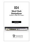
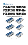
Multichannel AD & DA Converter
USER’S MANUAL
ED. 09/01
V. 1.1 - 14/05/2014
CONTENTS
1.
EQUIPMENT DESCRIPTION
1.1. BASIC DESIGN CONCEPTS
1.2. FUNCTIONAL SPECIFICATIONS
2.
EQUIPMENT POWER SUPPLY
3.
DESCRIPTION OF BACK PANEL AND CONNECTION
4.
OPERATION
4.1. SYNCHRONISM
4.2.A/D CONVERSION
4.3.D/A CONVERSION
5.
TECHNICAL CHARACTERISTICS
6.
A.E.Q. GUARANTEE
7.
ADITTIONAL INFORMATION
CADDY
Multichannel AD & DA Converter
2
1. EQUIPMENT DESCRIPTION
1.1. Basic design concepts
The CADDY AD/DA converter includes, in a single-rack unit, 12 converters that transform 2
analog audio channels to one AES-EBU (AES 3) digital stereo audio channel, and 12
converters that transform one AES-EBU (AES 3) digital stereo audio channel to two analog
audio channels.
1.2. Functional specifications:
It has excellent audio quality: 24 bits per sample, dynamic range greater than 100dB, audio
distortion level (THD+N) less than –80dB, and analog audio level up to + 22dBu.
It has a sample rate converter (SRC) at all digital inputs, allowing AES-EBU signals with sample
rates between 32 and 96kHz.
It has a high integration level: 12 each A/D and D/A converters in only one rack unit.
CADDY
Multichannel AD & DA Converter
3
2. EQUIPMENT POWER SUPPLY
The equipment receives power through the connector designed for that purpose, using the
cable supplied. The equipment may be operated with alternating voltage of between 90V and
250V at 50 or 60Hz. Maximum consumption is approximately 45W.
Activate the power switch (ON position). If all instructions have been correctly followed, the
Power ON LED will light up, indicating that the equipment is receiving power.
CADDY
Multichannel AD & DA Converter
4
3. DESCRIPTION OF BACK PANEL AND CONNECTION
1
2
3
IN
90 TO 250 VAC
50/60 Hz
7
OUT
AES-11
EXTERNAL
SYNC
7
5
OUT
STEREO CHANNELS 7-12
5
OUT
STEREO CHANNELS 1-6
STEREO CHANNELS 7-12
STEREO CHANNELS 1-6
IN
IN
DIGITAL AES/EBU
ANALOG
4
4
6
6
1.- Power Supply Connector and Fuseholder.
2.- External Synch Input.
3.- External Synch Output.
4.- Digital Inputs for D-A Converters.
5.- Analog Outputs for D-A Converters.
6.- Analog Inputs for A-D Converters
7.- Digital Outputs for A-D Converters.
CADDY
Multichannel AD & DA Converter
5
4. OPERATION
The CADDY basically converts 12 analog stereo signals to 12 AES-EBU digital stereo signals,
and 12 AES-EBU digital stereo signals to 12 analog stereo signals.
Internally, it always works with a resolution of 24 bits, both in A/D and D/A conversion.
4.1 Synchronism.
To perform all conversions, a sample rate must be established.
When the unit works independently, this rate is 48kHz. This means that the AES-EBU digital
outputs will have a 24-bit/48kHz format.
However, the application may require this rate to be changed. The AES-11 external sync input
allows the unit to work with a sample rate of 16kHz, 22.05kHz, 32kHz, 44.1kHz or 48kHz.
The AES-11 sync input signal connection is:
1 – GND
2 – SYNC IN+
3 – SYNC IN-
The AES-11 sync output connection allows conversion to be synchronized with another CADDY
or another piece of equipment:
1 – GND
2 – SYNC OUT+
3 – SYNC OUTIf several CADDY units are being used in the same system, even though they all work with a
default of 48kHz, one will have to be used as a master and the rest with external sync to avoid
jitter or lag in the conversion edges in the different units.
CADDY
Multichannel AD & DA Converter
6
4.2 A/D Conversion.
In the A/D conversion stage, analog stereo audio signals are converted to AES-EBU 24-bit
digital signals with the sample rate established by the external or internal sync signal.
The maximum input signal range to the converters is +22dBu. The input impedance is greater
than 6Kohms, and balancing is electronic. The signals enter at two DB25 female connectors:
The analog input connections are:
ANALOG IN STEREO CHANNELS 1-6
IN 1 L + PIN 1
IN 1 L - PIN 14
IN 1 R + PIN 2
IN 1 R – PIN 15
IN 2 L + PIN 3
IN 2 L – PIN 16
IN 2 R + PIN 4
IN 2 R – PIN 17
IN 3 L + PIN 5
IN 3 L – PIN 18
IN 3 R + PIN 6
IN 3 R – PIN 19
IN 4 L + PIN 7
IN 4 L – PIN 20
IN 4 R + PIN 8
IN 4 R - PIN 21
IN 5 L + PIN 9
IN 5 L – PIN 22
IN 5 R + PIN 10
IN 5 R – PIN 23
IN 6 L + PIN 11
IN 6 L – PIN 24
IN 6 R + PIN 12
IN 6 R – PIN 25
GND
SHIELD
ANALOG IN STEREO CHANNELS 7-12
IN 7 L + PIN 1
IN 7 L - PIN 14
IN 7 R + PIN 2
IN 7 R – PIN 15
IN 8 L + PIN 3
IN 8 L – PIN 16
IN 8 R + PIN 4
IN 8 R – PIN 17
IN 9 L + PIN 5
IN 9 L – PIN 18
IN 9 R + PIN 6
IN 9 R – PIN 19
IN 10 L + PIN 7
IN 10 L – PIN 20
IN 10 R + PIN 8
IN 10 R – PIN 21
IN 11 L + PIN 9
IN 11 L – PIN 22
IN 11 R + PIN 10
IN 11 R – PIN 23
IN 12L + PIN 11
IN 12 L – PIN 24
IN 12 R + PIN 12
IN 12 R – PIN 25
GND
SHIELD
CADDY
Multichannel AD & DA Converter
7
The AES-EBU digital outputs corresponding to these inputs are obtained in two DB25 male
connectors.
The digital output connections are:
DIGITAL OUT STEREO CHANNELS 1-6
OUT AES 1 +
PIN 1
OUT AES 1 PIN 2
OUT AES 2 +
PIN 3
OUT AES 2 PIN 4
OUT AES 3 +
PIN 5
OUT AES 3 PIN 6
OUT AES 4 +
PIN 7
OUT AES 4 PIN 8
OUT AES 5 +
PIN 9
OUT AES 5 PIN 10
OUT AES 6 +
PIN 11
OUT AES 6 PIN 12
SHIELD
SHELL
DIGITAL OUT STEREO CHANNELS 7-12
OUT AES 7 +
PIN 1
OUT AES 7 PIN 2
OUT AES 8 +
PIN 3
OUT AES 8 PIN 4
OUT AES 9 +
PIN 5
OUT AES 9 PIN 6
OUT AES 10 +
PIN 7
OUT AES 10 PIN 8
OUT AES 11 +
PIN 9
OUT AES 11 PIN 10
OUT AES 12 +
PIN 11
OUT AES 12 PIN 12
The format of these signals is AES-EBU 24-bit with 48KHz sample rate, or the one dictated by
the external sync signal.
CADDY
Multichannel AD & DA Converter
8
4.3 D/A Conversion.
The 12 AES-EBU signals are converted to 12 analog stereo signals by means of D/A
conversion.
It is important to know the sample rate used in these external signals and the internal work rate
(default 48kHz).
External AES-EBU signals can arrive at the CADDY input with any sample rate, as CADDY has
a sample rate converter circuit at each AES-EBU digital input, called SRC (sample rate
converter).
In the optimum operating range, these SRCs can synchronize with rates that are three times
higher or three times lower.
Thus, when working at 48kHz, the optimum range of sample rates for these signals would be
between 48/3 = 16kHz and 48*3 = 144kHz.
AES-EBU signals with rates lower than 16kHz or higher than 144kHz will be converted,
although some sporadic errors or faults may occur.
The AES-EBU digital inputs enter through two DB25 female connectors:
The digital input connections are:
DIGITAL IN STEREO CHANNELS 1-6
DIGITAL IN STEREO CHANNELS 7-12
IN AES 1 +
IN AES 1 IN AES 2 +
IN AES 2 IN AES 3 +
IN AES 3 IN AES 4 +
IN AES 4 IN AES 5 +
IN AES 5 IN AES 6 +
IN AES 6 SHIELD
IN AES 7 +
IN AES 7 IN AES 8 +
IN AES 8 IN AES 9 +
IN AES 9 IN AES 10 +
IN AES 10 IN AES 11 +
IN AES 11 IN AES 12 +
IN AES 12 SHIELD
PIN 1
PIN 2
PIN 3
PIN 4
PIN 5
PIN 6
PIN 7
PIN 8
PIN 9
PIN 10
PIN 11
PIN 12
SHELL
CADDY
Multichannel AD & DA Converter
PIN 1
PIN 2
PIN 3
PIN 4
PIN 5
PIN 6
PIN 7
PIN 8
PIN 9
PIN 10
PIN 11
PIN 12
SHELL
9
Once the signals have been converted into analog signals, they are obtained at two DB 25 male
connectors:
The analog output connections are:
ANALOG OUT STEREO CHANNELS 1-6
OUT 1 L +
PIN 1
OUT 1 L PIN 14
OUT 1 R +
PIN 2
OUT 1 R –
PIN 15
OUT 2 L +
PIN 3
OUT 2 L –
PIN 16
OUT 2 R +
PIN 4
OUT 2 R –
PIN 17
OUT 3 L +
PIN 5
OUT 3 L –
PIN 18
OUT 3 R +
PIN 6
OUT 3 R –
PIN 19
OUT 4 L +
PIN 7
OUT 4 L –
PIN 20
OUT 4 R +
PIN 8
OUT 4 R PIN 21
OUT 5 L +
PIN 9
OUT 5 L –
PIN 22
OUT 5 R +
PIN 10
OUT 5 R –
PIN 23
OUT 6 L +
PIN 11
OUT 6 L –
PIN 24
OUT 6 R +
PIN 12
OUT 6 R –
PIN 25
GND
SHIELD
ANALOG OUT STEREO CHANNELS 7-12
OUT 7 L +
PIN 1
OUT 7 L PIN 14
OUT 7 R +
PIN 2
OUT 7 R –
PIN 15
OUT 8 L +
PIN 3
OUT 8 L –
PIN 16
OUT 8 R +
PIN 4
OUT 8 R –
PIN 17
OUT 9 L +
PIN 5
OUT 9 L –
PIN 18
OUT 9 R +
PIN 6
OUT 9 R –
PIN 19
OUT 10 L +
PIN 7
OUT 10 L –
PIN 20
OUT 10 R +
PIN 8
OUT 10 R –
PIN 21
OUT 11 L +
PIN 9
OUT 11 L –
PIN 22
OUT 11 R +
PIN 10
OUT 11 R –
PIN 23
OUT 12L +
PIN 11
OUT 12 L –
PIN 24
OUT 12 R +
PIN 12
OUT 12 R –
PIN 25
GND
SHIELD
CADDY
Multichannel AD & DA Converter
10
5. TECHNICAL CHARACTERISTICS
•
•
•
•
•
•
•
•
•
•
•
•
•
•
•
•
•
•
•
•
•
24 physical analog audio inputs with electronic balancing.
24 physical analog audio outputs with electronic balancing.
12 AES-EBU (AES-3) physical digital audio outputs.
12 AES-EBU (AES-3) physical digital audio inputs with SRC.
1 AES-EBU (AES11) sync input and follower output.
Default sample rate (fs): 48kHz.
Standard allowable sample rate (fs) at sync input: 16kHz, 22.05kHz, 32kHz, 44.1kHz and
48kHz.
Internal resolution: 24 bits per sample.
Response frequency: 20-20,000 ± 1dB.
Total harmonic distortion + noise@1KHz <- 80dB.
Maximum analog audio level: + 22dBu.
Analog input impedance>6Kohms.
Analog output impedance: < 66ohms.
Analog input connectors: DB25 female.
Digital output connectors: DB25 male.
Digital input connectors: DB25 female.
Analog output connectors: DB25 male.
Sync input connector: XLR female.
Follower sync output connector: XLR male.
Power supply: 85-264VAC 50/60Hz, 45W
Format 1- 19" rack unit (482.6 x 44.5mm)
CADDY
Multichannel AD & DA Converter
11
6. A.E.Q. GUARANTEE
AEQ warrants that this product has been designed and manufactured under a certified Quality
Assurance System. AEQ therefore warrants that the necessary test protocols to assure the
proper operation and the specified technical characteristics of the product have been followed
and accomplished.
This includes that the general protocols for design and production and the particular ones for
this product are conveniently documented.
1.- The present guarantee does not exclude or limit in any way any legally recognized right of
the client.
2.- The period of guarantee is defined to be twelve natural months starting from the date of
purchase of the product by the first client.
To be able to apply to the established in this guarantee, it is compulsory condition to inform the
authorized distributor or –to its effect- an AEQ Sales office or the Technical Service of AEQ
within thirty days of the appearance of the defect and within the period of guarantee, as well as
to facilitate a copy of the purchase invoice and serial number of the product.
It will be equally necessary the previous and expressed conformity from the AEQ Technical
Service for the shipment to AEQ of products for their repair or substitution in application of the
present guarantee.
In consequence, return of equipment that does not comply with these conditions will not be
accepted.
3.- AEQ will at its own cost repair the faulty product once returned, including the necessary
labour to carry out such repair, whenever the failure is caused by defects of the materials,
design or workmanship. The repair will be carried out in any of the AEQ authorized Technical
Service Centre. This guarantee does not include the freight charges of the product to or from
such Authorized Technical Service Centre.
4.- No Extension of the Guarantee Period for repaired product shall be applied. Nor shall a
Substituted Products in application of this Guarantee be subject to Guarantee Period Extension.
5.- The present guarantee will not be applicable in the following situations:
improper use or Contrary use of the product as per the User or Instruction Manual; violent
manipulation; exhibition to humidity or extreme thermal or environmental conditions or sudden
changes of such conditions; electrical discharges or lightning; oxidation; modifications or not
authorized connections; repairs or non-authorized disassembly of the product; spill of liquids or
chemical products.
6.- Under no circumstances, whether based upon this Limited Guarantee or otherwise, shall
AEQ, S.A. be liable for incidental, special, or consequential damages derived from the use or
from the impossibility of using the product.
AEQ shall not be liable for loss of information in the disks or data support that have been altered
or found to be inexact, neither for any accidental damage caused by the user or other persons
manipulating the product.
CADDY
Multichannel AD & DA Converter
12
7. ADITTIONAL INFORMATION
NOTE: This equipment complies with the limits for a Class A digital device, pursuant to
part 15 of the FCC Rules. These limits are designed to provide reasonable protection
against harmful interference when the equipment is operated in a commercial
environment. This equipment generates, uses, and can radiate radio frequency energy
and, if not installed and used in accordance with the instruction manual, may cause
harmful interference to radio communications. Operation of this equipment in a residential
area is likely to cause harmful interference in which case the user will be required to
correct the interference at his own expense.
CADDY
Multichannel AD & DA Converter
13