1
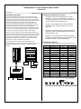
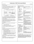
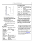
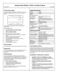
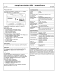
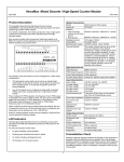
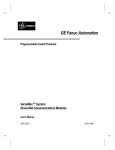
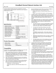
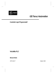
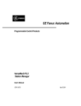
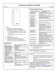
Analog Input, 16-Bit Thermocouple Module IC200ALG630 January 2012 GFK-1700M Product Description Module Characteristics The IC200ALG630 Analog Input Thermocouple Module is an intelligent module that accepts seven independent thermocouple or millivolt inputs. Channels Seven thermocouple or millivolt inputs Module ID FFFF9804 The module receives power from the backplane power supply. No external power source is required. Isolation: User input to logic (optical) and to frame ground Group to group Channel to channel OK LED indicators ANALOG INPUT THERMOCOUPLE 1234567 16BIT 7CH External power supply None Thermal derating Diagnostics None The Analog Input Thermocouple Module uses the following data types: J, K, T, S, R, none (used for mV inputs) Spans (+/–) 19.5mV, 39mV, 78.125mV, 156.25mV, 312.5mV, 625mV Converter resolution 15 bits + sign Cold junction compensation If used, reference junction temperature is measured at thermocouple termination using a precision thermistor, or supplied by system, or by fixed configuration value. Cold junction temperature error +/–0.25 degree Celsius (local measurement). To reduce temperature transients, thermocouple terminations should not be installed in the same cabinet as heat dissipation assemblies. Conformity error +/–0.3 degree Celsius, +/–0.5 degree Fahrenheit. Accuracy, at 25° C on voltage measurement: on temp. measurement: +/–0.2% +/- 3 degrees Celsius. Temperature sensitivity (0° to 60°C) +/–0.004% of reading, +/–1.5µV per ° Celsius referred to input Normal mode rejection 60dB, at 50/60 Hz, 100% span Common mode rejection 120 dB at 50/60Hz, 100 ohm imbalance 7 words of analog input data. 7 optional words of analog output data. The module exchanges data in the same manner as other types of I/O modules: it provides all its input data when requested. Diagnostics The Analog Input Thermocouple Module performs diagnostics and provides the following information. ▪ ▪ Open Thermocouple, over/under range, and high/low alarm, thermistor fault (reported as internal fault). Thermocouple types Host Interface ▪ OK LED: Green indicates backplane power is present. Amber indicates module fault. Input Characteristics The module automatically performs A/D calibration at powerup. Automatic calibration is then repeated periodically to compensate for changes in the ambient temperature. New calibration values are filtered into the current calibration values. ▪ Not applicable None Backplane current consumption 5V output: 125mA maximum. 3.3V output: 125mA maximum. 831 Each input channel can be configured to report millivolts ranges as 1/100 of millivolts, or thermocouple inputs as linearized temperature in tenths of degrees Celsius or Fahrenheit, with or without cold junction compensation. ▪ ▪ 250VAC continuous; 1500VAC for 1 minute Alarm faults are reported if the processed value for a channel exceeds its configured alarm limit. Common mode voltage 3 VDC maximum Over/underrange faults are reported if the millivolt value for an input exceeds the limits of its span. Maximum voltage between channels 50V Open circuit is checked every time a thermocouple input is read (unless Open TC checking is disabled). If the circuit is open, a fault is reported and the input defaults to the configured channel default. Normal mode voltage 5 VDC maximum Scan time 60 Hz: approximately 60 milliseconds per point 50 Hz: approximately 70 milliseconds per point. Thermistor fault will be reported as Internal fault in the I/O Fault table. Preinstallation Check A thermistor fault occurs if the calculated temperature value from the thermistor is less than -10 °C or greater than +75 °C. Carefully inspect all shipping containers for damage. If any equipment is damaged, notify the delivery service immediately. Save the damaged shipping container for inspection by the delivery service. After unpacking the equipment, record all serial numbers. Save the shipping containers and packing material in case it is necessary to transport or ship any part of the system. LED Indicators The green OK LED is on when backplane power is present to the module. If this LED is amber, it indicates a module fault. 1 Analog Input, 16-Bit Thermocouple Module IC200ALG630 January 2012 GFK-1700M Installation Instructions Installation in Hazardous Locations The preferred installation technique is to mount the Thermocouple Module on a Connector-style I/O Carrier and connect thermocouples to an Interposing Thermocouple Carrier as shown below. The Interposing Thermocouple-style I/O Carrier provides both box-style wiring terminals and a built-in thermistor for Local Cold Junction Compensation. It connects to the Connector-Style Carrier via a cable as shown. This allows the thermocouple connections to be located away from the I/O modules in the system. Each TC terminal on the Interposing Thermocouple Carrier accommodates one solid or stranded AWG #14 2 2 (avg. 2.1mm cross section) to AWG #22 (avg. 0.36mm cross section) 2 wire, or two wires up to AWG #18 (avg. 0.86mm cross section). EQUIPMENT LABELED WITH REFERENCE TO CLASS I, GROUPS A, B, C & D, DIV. 2 HAZARDOUS LOCATIONS IS SUITABLE FOR USE IN CLASS I, DIVISION 2, GROUPS A, B, C, D OR NON-HAZARDOUS LOCATIONS ONLY WARNING - EXPLOSION HAZARD - SUBSTITUTION OF COMPONENTS MAY IMPAIR SUITABILITY FOR CLASS I, DIVISION 2; WARNING - EXPLOSION HAZARD - WHEN IN HAZARDOUS LOCATIONS, TURN OFF POWER BEFORE REPLACING OR WIRING MODULES; AND WARNING - EXPLOSION HAZARD - DO NOT DISCONNECT EQUIPMENT UNLESS POWER HAS BEEN SWITCHED OFF OR THE AREA IS KNOWN TO BE NONHAZARDOUS. However, it is also possible to mount the Thermocouple Module on one of the terminal-style carriers (box-style, spring-style, or barrier-style) and provide Local Cold Junction Compensation by using a kit that includes the correct type of thermistor, as described in the I/O Modules User Manual. Both methods are shown below. The thermistor kit must be installed on the A9 and A10 terminals of the carrier. If the module will only be used to measure millivolt inputs, not thermocouple inputs, it can be mounted on any type of I/O Carrier. The thermistor terminals A9 and A10 cannot be used as millivolt input terminals. Thermocouple or Millivolt Inputs Field Wiring Terminals The terminal assignments shown below are the same for all carriers. Number A1 A2 A3 A4 A5 A6 A7 A8 A9 A10 A11 A12 A13 A14 A15 A16 A17 A18 Thermocouple or Millivolt Inputs Install Optional Thermistors Here CHS014 Thermocouple Inputs Built-In Thermistors Located Here Connection Channel 1 (+) Channel 1 (-) Channel 2 (+) Channel 2 (-) Channel 3 (+) Channel 3 (-) Channel 4 (+) Channel 4 (-) (Thermistor (+)) (Thermistor (-)) Channel 5 (+) Channel 5 (-) Channel 6 (+) Channel 6 (-) Channel 7 (+) Channel 7 (-) No connection No connection Number B1 B2 B3 B4 B5 B6 B7 B8 B9 B10 B11 B12 B13 B14 B15 B16 B17 B18 Connection No connection Shield No connection Shield No connection Shield No connection Shield No connection Shield No connection Shield No connection Shield No connection No connection No connection No connection Wiring Connections for Carriers with Two Rows of Terminals: Thermocouple Inputs Note: only for thermocouple carrier Thermistor AI 1 A 2 1 AI 2 2 3 AI 3 4 5 AI 5 AI 4 6 7 8 9 10 11 12 AI 6 13 AI 7 14 15 16 17 18 Analog Input, 16-Bit Thermocouple Module IC200ALG630 January 2012 GFK-1700M Wiring Connections for Carriers with Three Rows of Terminals: A AI 6 13 AI 7 14 15 16 17 Thermistor AI 4 7 8 9 AI 1 1 Revision IC200ALG630-EC BXIOAI7-EC 10 3 IC200ALG630-DC BXIOAI7-DC Note: only for thermocouple carrier AI 5 11 AI 2 2 18 IC200ALG630-DB BXIOAI7-DB 12 IC200ALG630-CB BXIOAI7-CB AI 3 4 5 6 Cable Shield Connections Shielded twisted pair cable is recommended for the analog channel connections. If possible, the cable should be grounded at the source device. If that is not possible, the cable shield must be grounded at the I/O module. This can be done using an Auxiliary I/O Terminal strip. Improved reporting of Open Input error at higher temperatures. IC200ALG630-AB BXIOAI7-AB June 2001 Firmware version 1.01. Enhanced Open Circuit reporting IC200ALG630-AA BXIOAI7-AA July 1999 Initial product release ▪ January 2012 Label change. No changes to features, performance or compatibility. Firmware release 1.25. Resolves component obsolescence issue. No change to features, performance or compatibility. ▪ February 2011 Labeling change. No changes to compatibility, functionality or performance. September 2010 Firmware release 1.24. Resolved fault reporting issue in Remote/Local IO configuration. IC200ALG630-GD August 2009 Changed manufacturing location. No changes to compatibility, functionality or performance. IC200ALG630-FD BXIOAI7-FD October 2008 Updated Power Supply OK signal circuitry. IC200ALG630-ED BXIOAI7-ED November 2002 Description IC200ALG630-GE IC200ALG630-FE September 2007 January 2004 ATEX approval for Group 2 Category 3 applications. PLC CPU Firmware version 1.20 or later. Ethernet NIU EBI001 all versions. Genius NIU GBI001 Firmware version 1.10 or later* Profibus NIU PBI001 Firmware version 1.10 or later* Restrictions and Open Issues Product Revision History IC200ALG630-HE Changed to V0 plastic for module housing. DeviceNet NIU DBI001 Firmware version 1.10 or later. The DeviceNet NIU does not support software configuration. Therefore, analog modules used with a DeviceNet NIU must be autoconfigured and use only their default configuration settings. * For GBI001, NIU version 2.0 or above is required to perform software configuration. For PBI001, NIU version 2.01 or above is required to perform software configuration. JF 1.25 44A750342-G05. Available as a free download at http://ge-ip.com/support. April 2011 April 2004 IC200ALG630-BB BXIOAI7-BB ▪ ▪ ▪ ▪ ▪ Product Version Information IC200ALG630-HF February 2005 Configurable for 50Hz line frequency This module is compatible with: If the module is installed on a Connector-style I/O Carrier, the cable shield can be connected directly to an Interposing Terminal. A shielded interposing cable (shielded cables are available separately) must be used between the Connector-style I/O Carrier and the Interposing Terminal. An Auxiliary I/O Terminal Strip can also be added to the Interposing Terminal if additional shield connections are required. Date Plastic change on locking mechanism Firmware version 1.25 is compatible with all hardware versions of the ALG630. If the module is installed on a Compact Terminal-style I/O Carrier, shield connections can be made on an Auxiliary I/O Terminal that is mounted near the I/O carrier. Revision IC200ALG630-JF April 2005 Description Compatibility If the module is installed on a Terminal-style I/O Carrier, shield connections can be made on an Auxiliary I/O Terminal that is attached to the I/O carrier. Revision letters: Firmware version: Firmware upgrades: Date ▪ Firmware release 1.20. Improved I/O scanning. 3 Additional faults may be logged when a new configuration containing parameter changes such as the Alarm High limit or Alarm Low limit in the hardware configuration of an analog module is stored followed by a Clear All operation. The additional faults are logged against the previous configuration. This issue is observed when Machine Edition is connected to Versamax CPUs (IC200CPU001, IC200CPU002, IC200CPU005 and IC200CPUE05) and does not occur with Versamax NIUs (IC200GBI001, IC200EBI001, IC200PBI001, and IC200DBI001). When more than 20 faults are sent to a GBC70 within a single Genius scan, under rare conditions one fault or fault contact may not be reported by the GBC70. This has been observed when simultaneous open wire condition occurs in all eight channels of IC200ALG240 module or if several I/O modules in a GNIU rack generate multiple faults simultaneously. This issue has only been observed when the GBC70 was in a rack with an RX7i CPU. When 45 or more faults are sent to a GBC70 within a single Genius scan, a few faults or fault contacts may not be reported by the GBC70. This is most likely to be caused by the sudden loss of numerous blocks at each bus controller in the system. The resulting PLC diagnostics and diagnostic contacts may be incorrect. Analog Input, 16-Bit Thermocouple Module IC200ALG630 January 2012 GFK-1700M Configuration Operational Notes ▪ ▪ The default parameters of the Thermocouple Input module can be used in many applications. The module can be software-configured when it is installed in a PLC system, or an I/O Station controlled by an NIU that supports software configuration. If hot insertion of a module is done improperly, the operation of other modules on the same backplane may be disrupted. See Installing a Module on a Carrier in the VersaMax Modules Manual, GFK-1504. Clarification of Default/Hold Last State configurations: If there is an error on a specific input channel, the modules will always report the Channel Default value from the Input Parameters tab of the module configuration. When a Loss of I/O Module fault is logged for a module, the CPU or NIU will use the Default/Hold Last State setting from the Module Parameters tab of the module configuration to determine what value should be reported to the reference tables. ▪ ▪ ▪ ▪ After an Open Circuit fault condition is corrected, the module takes a few seconds to return to normal operation. During this time, the module continues reporting the channel default input value. After the module has recovered from the Open Circuit fault, it returns to normal inputs and normal operation. Parameter Default Choices Analog Input Data Length Analog Input Data Reference Analog Output Data Length Analog Output Data Reference Line Frequency Suppress Open Thermocouple Channel Active Engineering Units 7 1 to 7 user selectable 0 0 to 7 Thermocouple Type Range R J Type Alarm Low Alarm High Reference Junction Value Correction Factor Channel Default Input Cold Junction Default If there is a very large change in an input (for example, an input quickly goes from 50mV to 400mV), the module may briefly report an Over-range fault on that circuit even though the circuit is not actually over its configured upper range limit. This is only temporary. When IC200ALG630 or IC200ALG620 modules are present in GNIU or PNIU rack and a 'Clear all' command is issued from Machine Edition software, Machine Edition may get disconnected, displaying timeout error "error 8097 - host disconnect has occurred". When this error is logged, the Configuration is still cleared. To avoid this error, the “Request Timeout” value in “Additional Configuration” in “Target Properties” should be increased to 30s or more. user selectable 60 Hz No 50 Hz, 60 Hz Yes, No Active 1/10 degrees C J 625 Local –2000 8000 250 0 0 250 Inactive (off), Active (on) Millivolts, 1/10 degrees C, 1/10 degrees F None, J, K, T, S, R 19.53, 39.06, 78.125, 156.25, 312.5, 625. Local, Remote, Fixed, None –32,768 to +32,767 –32,768 to +32,767 –32,768 to +32,767 –32,768 to +32,767 +32,767 +32,767 Configurable Features Channel Active: Each channel can be configured as either active or inactive. If a channel is inactive, the filtering, scaling, calibration, and alarm checks are omitted for that channel, and a value of 0 is returned for the channel. The reference parameter for the analog input data returns the byte length and is independent of the number of active channels. When all the channels of IC200ALG630 are set inactive and the Reference Junction Type parameter is not set to "local", VersaMax CPUs / NIUs will report a “Loss of IO modules” fault, that points to the IC200ALG630 itself. To avoid this fault, either configure at least one thermocouple channel to active or set reference junction type parameter to “local”. Low Alarm Limit and High Alarm Limit: Each input channel can have a low alarm limit and a high alarm limit. If an input reaches one of its limits, the module reports the actual value and sends the appropriate diagnostic input bit. Alarms do not stop the process or change the value of the input. Alarm limits can be set anywhere over the dynamic range of the signal. The range for each is –32,768 to +32,767. The high alarm limit must be greater than the low alarm limit. If alarm reporting is not wanted, alarm limits can be set beyond the dynamic range of the signal so they will never be activated. Thermocouple Limits: The table below lists millivolt and temperature limits for applicable thermocouple types. TC Low mV High mV Low High Type Limit Limit Temperature Temperature Limit (C) Limit (C) 4 J –8.0960 57.9420 –210.00 1000.00 K –5.8910 54.8069 –200.00 1370.00 T –5.6030 20.2520 –200.00 390.00 S –0.1940 18.5040 –40.00 1750.00 R –0.1880 20.8780 –40.00 1750.00 Analog Input, 16-Bit Thermocouple Module IC200ALG630 January 2012 GFK-1700M Cold Junction Compensation: The Thermocouple module provides four choices for Cold Junction Compensation. ▪ ▪ ▪ ▪ No Cold Junction Compensation: This is used for millivolt inputs or if cold junction is maintained at 0 degrees C. Remote Cold Junction Compensation: With this option, cold junction is measured externally and provided to the module from the application, via the module’s analog output (word output) data. If the module has multiple thermocouples that are configured for remote compensation, the same compensation value must be used by each. Fixed Cold Junction Compensation: This option uses a fixed compensation value provided by the user in the configuration parameter, “Reference Junction Value.” The units of this fixed value are defined in configuration parameter “Engineering Units.” Local Cold Junction Compensation: The best way to provide local compensation is with an Interposing Thermocouple Carrier, which has a built-in thermistor. Using an Interposing Carrier allows the thermocouple connections to be placed farther away from the I/O modules in the system, which helps shield thermocouple connections from module heat. If Local Cold Junction Compensation is configured and an Interposing Thermocouple Carrier is not used, a separate thermistor must be installed directly at the module’s I/O Carrier, using the Thermistor (+) and Thermistor (–) terminals. The thermistor must be the type specified in the I/O Modules User’s Manual. Note: If Local Compensation is selected but an Interposing Thermocouple Carrier or local thermistor is not used, erroneous temperatures may be reported and a thermistor error will be reported in the fault table. Range Selection: The module is configurable for any of six different millivolt ranges (+/–): 19.5mV, 39mV, 78.125mV, 156.25mV, 312.5mV, and 625mV. All but the last provide input readings in hundredths of millivolts. For the 625mV range, inputs are in tenths of millivolts. When used to read millivolts, the Thermocouple Type configuration parameter must be set to “none”. 5