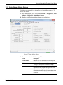
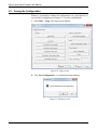
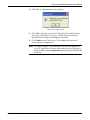
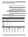
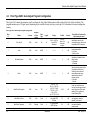
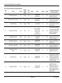
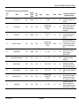
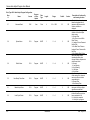
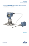
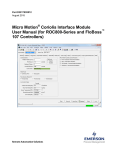
1
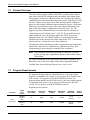
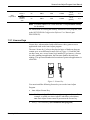
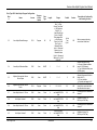
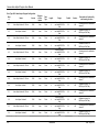
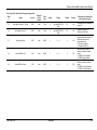
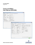
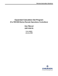
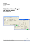
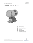
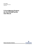
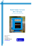
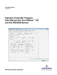
Part Number D301198X012 Form A6153 July 2015 Sensus Auto-Adjust™ Program (for ROC800-Series Remote Operations Controllers) User Manual Remote Automation Solutions Sensus Auto-Adjust Program User Manual Revision Tracking Sheet July 2015 This manual may be revised periodically to incorporate new or updated information. The revision date of each page appears at the bottom of the page opposite the page number. A change in revision date to any page also changes the date of the manual that appears on the front cover. Listed below is the revision date of each page (if applicable): Page All pages All pages All pages All pages Initial release ii Revision July-2015 October-2010 March-2009 May-2006 December-2003 Contents Rev. July-2015 Sensus Auto-Adjust Program User Manual Contents Page Chapter 1 – Introduction 1-1 1.1 Scope and Organization.....................................................................................................1-1 1.2 Product Overview ...............................................................................................................1-2 1.3 Program Requirements ......................................................................................................1-2 1.3.1 License Keys ..........................................................................................................1-3 Chapter 2 – Installation 2-1 2.1 Wiring the Auto-Adjust Turbo-Meter (using Pulse Input Module) ......................................2-1 2.2 Wiring the Auto-Adjust Turbo-Meter (using Advanced Pulse Module) ..............................2-3 2.3 Installing the License Key ..................................................................................................2-5 2.3.1 Verifying the License Key Installation .....................................................................2-6 2.4 Downloading the Auto-Adjust.tar Program.........................................................................2-7 Chapter 3 – Configuration 3-1 3.1 Auto-Adjust Configuration Screen......................................................................................3-3 3.2 Auto-Adjust Alarms Screen ................................................................................................3-7 3.3 Saving the Configuration ................................................................................................. 3-10 Chapter – 4 Reference Materials 4-1 4.1 Example Calibration Data Report ......................................................................................4-1 4.2 Point Type 62/63: Auto-Adjust Program Configuration ......................................................4-3 iii Contents Rev. July-2015 Sensus Auto-Adjust Program User Manual [This page is intentionally left blank.] iv Contents Rev. July-2015 Chapter 1 – Introduction This chapter describes the structure of this manual and presents an overview of the Sensus Auto-Adjust™ Program for the ROC800-Series Remote Operations Controller. In This Chapter 1.1 1.2 1.3 1.1 Scope and Organization .................................................................. 1-1 Product Overview ............................................................................ 1-2 Program Requirements.................................................................... 1-2 1.3.1 License Keys ...................................................................... 1-3 Scope and Organization This document serves as the user manual for the Sensus Auto-Adjust™ Turbo-Meter program, which is intended for use in the ROC800-Series Remote Operations Controllers (“ROC800s”). This manual describes how to download, install, and configure the Sensus Auto-Adjust Turbo-Meter user program (referred to as the “Auto-Adjust program” or “the program” throughout the rest of this manual). You access and configure this program using ROCLINK 800 Configuration Software loaded on an IBMcompatible personal computer running Windows 2000 (with Service Pack 2), XP, Vista or Windows 7. The sections in this manual provide information in a sequence appropriate for first-time users. Once you become familiar with the procedures and the software, the manual becomes a reference tool. This manual has the following major sections: Section 1 – Introduction Section 2 – Installation Section 3 – Configuration Section 4 – Reference This manual assumes that you are familiar with the ROC800s and their configuration. For more information, refer to the following manuals: Rev. July-2015 ROC800-Series Remote Operations Controller Instruction Manual (part D301217X012) ROCLINK 800 Configuration Software User Manual (part D301250X012) Introduction 1-1 Sensus Auto-Adjust Program User Manual 1.2 Product Overview The Auto-Adjust program enables a ROC800 to read the pulse counters once each second for all configured and run-enabled Auto-Adjust points. The program calculates an “adjusted volume rate” based on the frequency variations between the main and sensing rotors on the Turbo-Meter. Using the AAT Volume and % Error values from the Turbo-Meter calibration report (see the example calibration report included in Section 4, Reference Materials), you enter these values in the Auto-Adjust Calibration Curve pane on the Auto-Adjust Configuration screen (see Figure 16). The program uses these calibration-based correction values to calculate an “adjusted uncorrected volume factor,” or AUVF. If you enable the Autoadjust calibration curve, the program applies the AUVF factor to the adjusted volume rate. The adjusted volume rate is the parameter that should be used as the uncorrected volume input to the AGA 7 calculations, which results in a volume flow rate at base conditions. The adjusted volume calculation provides a measurement registration that adjusts flow values back to original factory calibration accuracy, thus compensating for meter changes or abnormal flow conditions. Note: When using the Auto-Adjust program on a ROC800, you don’t need to use any other equipment to interface with an Auto-Adjust Turbo-Meter. For further information on the Auto-Adjust calculations, equations, and flowcharts, refer to the Auto-Adjust Turbo-Meter Algorithms manual available from Sensus Metering Systems (www.sensus.com). 1.3 Program Requirements For programs being installed on a ROC800-Series 1, the Auto-Adjust program is compatible with version 2.02 (or greater) of the firmware and with version 1.74 (or greater) of the ROCLINK 800 software. For programs being installed on a ROC800-Series 2, the Auto-Adjust program is compatible with version 3.00 (or greater) of the firmware and with version 1.87 (or greater) of the ROCLINK 800 software. Program specifics include: File Name AutoAdjust.62.tar 1-2 Target Unit/ Version User Defined Point (UDP) Flash Used (in bytes) SRAM Used (in bytes) DRAM Used (in bytes) ROCLINK 800 Version Display Number ROC800 Series 1 2.02 62 28874 2631 114688 1.74 (or greater) 5, 6 ROC800 Series 2 3.00 62 28874 2631 114688 1.87 (or greater) 5, 6 Introduction Rev. July-2015 Sensus Auto-Adjust Program User Manual AutoAdjust.63.tar ROC800 Series 1 2.02 63 28874 2631 114688 1.74 (or greater) 5, 6 ROC800 Series 2 3.00 63 28874 2631 114688 1.74 (or greater) 5, 6 Note: You must connect a PC to the ROC800’s LOI port before starting the download. For information on viewing the memory allocation of user programs, refer to the ROCLINK 800 Configuration Software User Manual (part D301250X012). 1.3.1 License Keys License keys, when matched with valid license codes, grant access to applications such as the Auto-Adjust program. The term “license key” refers to the physical piece of hardware that can contain up to seven different licenses (refer to Figure 1). Each ROC800 can have none, one, or two license keys installed. If you remove a license key after enabling an application, the firmware disables the task from running. This prevents unauthorized execution of protected applications in a ROC800. J1 U1 DOC0422A Figure 1. License Key You must install the following license keys to use the Auto-Adjust Program. Auto-Adjust License Key. Note: Each Auto-Adjust Turbo-Meter requires a separate license. For example, to enable two Auto-Adjust Turbo-Meter calculations, two Auto-Adjust licenses must be present on the license key. Rev. July-2015 AGA_3/7/8 License Key (not included in this program). Introduction 1-3 Sensus Auto-Adjust Program User Manual [This page is intentionally left blank.] 1-4 Introduction Rev. July-2015 Sensus Auto-Adjust Program User Manual Chapter 2 – Installation This section provides instructions for installing the Auto-Adjust program. Read Section 1.3 of this manual for program requirements. Note: The program and license key can be installed in any order. The manual shows the installation of the license key first. In This Chapter 2.1 Wiring the Auto-Adjust Turbo-Meter (using Pulse Input Module) ............... 2-1 2.2 Wiring the Auto-Adjust Turbo-Meter (using Advanced Pulse Module) ....... 2-3 2.3 Installing the License Key ........................................................................... 2-5 2.3.1 Verifying the License Key Installation ................................................ 2-6 2.4 Downloading the Auto-Adjust Program....................................................... 2-7 2.1 Wiring the Auto-Adjust Turbo-Meter (using Pulse Input Module) Wiring a ROC800 to a Sensus Auto-Adjust™ Turbo-Meter requires that you use a Dual-Channel safety barrier. You can purchase the safety barrier from Sensus. Install the safety barrier in the Safe Area with the ROC800, not in the Hazardous Area with the Turbo-Meter. You can install either a blade tip sensor Turbo-Meter (refer to Figure 2 and Invensys drawing MM-1922-B) or a slot sensor Turbo-Meter (refer to Figure 3 and Invensys drawing MM-2126-B). If you are installing a blade tip sensor Turbo-Meter, refer to Figure 2 and Invensys drawing MM-1922-B. Use two Dual-Channel safety barriers and a power safety barrier. The power for each of the Dual-Channel safety barriers should be 24 volt dc. You cannot power both barriers from the Pulse Input module. Rev. July-2015 Installation 2-1 Sensus Auto-Adjust Program User Manual Figure 2. Turbo-Meter with Blade Tip Sensor Installation (Pulse Input Module) If you are installing a slot sensor Turbo-Meter, refer to Figure 3 and Invensys drawing MM-2126-B. The power for the Dual-Channel safety barrier can come from the Pulse Input module’s +T connection. When you configure the PI module (using ROCLINK 800), set the +T channel to 24 Volts dc. 2-2 Installation Rev. July-2015 Sensus Auto-Adjust Program User Manual Figure 3. Turbo-Meter with Slot Sensor Installation (Pulse Input Module) Note: For either the blade tip or slot sensor Turbo-Meter, be sure to follow all instructions on the Invensys drawings and on any literature that accompanies the safety barrier and Turbo-Meter. 2.2 Wiring the Auto-Adjust Turbo-Meter (using Advanced Pulse Module) Wiring a ROC800 to a Sensus Auto-Adjust™ Turbo-Meter requires that you use a Dual-Channel safety barrier. You can purchase the safety barrier from Sensus. Install the safety barrier in the Safe Area with the ROC800, not in the Hazardous Area with the Turbo-Meter. You can install either a blade tip sensor Turbo-Meter (refer to Figure 4) or a slot sensor Turbo-Meter (refer to Figure 5). If you are installing a blade tip sensor Turbo-Meter, refer to Figure 4. Use two Dual-Channel safety barriers and a power safety barrier. The power for each of the Dual-Channel safety barriers should be 24 volt dc. You cannot power both barriers from the Advanced Pulse Module. Rev. July-2015 Installation 2-3 Sensus Auto-Adjust Program User Manual Figure 4. Turbo-Meter with Blade Tip Sensor Installation (Advanced Pulse Module) If you are installing a slot sensor Turbo-Meter, refer to Figure 5. The power for the Dual-Channel safety barrier can come from the Pulse Input module’s +T connection. When you configure the PI module (using ROCLINK 800), set the +T channel to 24 Volts dc. 2-4 Installation Rev. July-2015 Sensus Auto-Adjust Program User Manual Figure 5. Turbo-Meter with Slot Sensor Installation (Advanced Pulse Module) Note: For either the blade tip or slot sensor Turbo-Meter, be sure to follow all instructions on the drawings and on any literature that accompanies the safety barrier and Turbo-Meter. 2.3 Installing the License Key If you order the Auto-Adjust program for a new ROC800, your ROC800 is delivered with the license key installed. Go to Section 2.3. If you order the program for an existing ROC800, you must install the license key yourself. Caution Failure to exercise proper electrostatic discharge precautions, such as wearing a grounded wrist strap may reset the processor or damage electronic components, resulting in interrupted operations. When working on units located in a hazardous area (where explosive gases may be present), make sure the area is in a non-hazardous state before performing these procedures. Performing these procedures in a hazardous area could result in personal injury or property damage. To install a license key: 1. Remove power from the ROC800. 2. Remove the wire channel cover. 3. Unscrew the screws from the Central Processing Unit (CPU) faceplate. 4. Remove the CPU faceplate. 5. Place the license key in the appropriate terminal slot (P4 or P6) in the CPU. Rev. July-2015 Installation 2-5 Sensus Auto-Adjust Program User Manual DOC0423A Figure 6. License Key Installation Note: When using a single license key, install it in slot P4. 6. Press the license key into the terminal until it is firmly seated (refer to Figure 6). 7. Replace the CPU faceplate. 8. Replace the screws on the CPU faceplate. 9. Replace the wire channel cover. 10. Restore power to the ROC800. 2.3.1 Verifying the License Key Installation After you install the license key, you can verify whether the ROC800 recognizes the key. From the ROCLINK 800 screen, select Utilities > License Key Administrator. The License Key Administrator screen displays: Figure 7. License Key Administrator The Auto-Adjust program appears in the Application Name column. (For further information on the License Key Administrator screen, refer to the ROCLINK 800 Configuration Software User Manual (part D301250X012). 2-6 Installation Rev. July-2015 Sensus Auto-Adjust Program User Manual Note: The value in the App Code field on this screen indicates the total number of supported meters available on this ROC800. After you verify that the license key is correctly installed and recognized, proceed to Section 2.3. 2.4 Downloading the Auto-Adjust Program This section provides instructions for installing the Auto-Adjust program file into the Flash memory on the ROC800. Note: Two versions of the program are included. Installation and operation are identical between the two programs, but they use different point type locations. The manual shows installation of Auto-Adjust.62.tar. Choose the version of the program that uses a point type not currently in use by other programs on your ROC800. To download the program using ROCLINK 800 software: 1. Connect the ROC to your computer using the LOI port. 2. Start and logon to ROCLINK 800. 3. Select Utilities > User Program Administrator from the ROCLINK menu bar. The User Program Administrator screen displays (see Figure 8): Figure 8. User Program Administrator Rev. July-2015 Installation 2-7 Sensus Auto-Adjust Program User Manual 4. Select any empty program number (in this case, number 1) in which to download the program. 5. Click Browse in the Download User Program File frame. The Select User Program File screen displays (see Figure 9). 6. Select the path and user program file to download from the CD-ROM. (Program files are typically located in the Program Files folder on the CD-ROM.) As Figure 9 shows, the screen lists all valid user program files with the .TAR extension: Figure 9. Select User Program File 7. Click Open to select the program file. The User Program Administrator screen displays. As shown in Figure 10, note that the Download User Program File frame identifies the selected program and that the Download & Start button is active: 2-8 Installation Rev. July-2015 Sensus Auto-Adjust Program User Manual Figure 10. User Program Administrator 8. Click Download & Start to begin loading the selected programs. The following message displays: Figure 11. Confirm Download 9. Click Yes to begin the download. When the download completes the following message displays: Rev. July-2015 Installation 2-9 Sensus Auto-Adjust Program User Manual Figure 12. ROCLINK 800 Download Confirmation 10. Click OK. The User Program Administrator screen displays (see Figure 13). Note that: The Device User Program Environment frame reflects the use of system memory. The User Programs Installed in Device frame identifies the installed program(s). Figure 13. User Program Administrator 11. Click Close. The ROCLINK 800 screen displays and the download is complete. 2-10 Installation Rev. July-2015 Sensus Auto-Adjust Program User Manual Figure 14. ROCLINK 800 Rev. July-2015 Installation 2-11 Sensus Auto-Adjust Program User Manual [This page is intentionally left blank.] 2-12 Installation Rev. July-2015 Sensus Auto-Adjust Program User Manual Chapter 3 – Configuration After you have loaded the Auto-Adjust program on the ROC800, you configure the program using two program-specific screens (Auto-Adjust Configuration and Auto-Adjust Alarms): Use the Auto-Adjust Configuration screen to set a number of program configuration values (including inputs, factor values, and other parameters) and enable the calculations. Use the Auto-Adjust Alarms screen to view active program-specific alarms. In This Chapter 3.1 3.2 3.3 Auto-Adjust Configuration Screen ................................................... 3-3 Auto-Adjust Alarms Screen ............................................................. 3-7 Saving the Configuration ............................................................... 3-10 To configure the program (after logging onto ROCLINK 800 and successfully installing the program and license key), proceed through the program screens as shown in this section. Note: Once you have completed the configuration process for the Auto- Adjust program, review the ROCLINK 800 turbine meter setup screen and the station setup screen to which the turbine meter belongs to determine if any additional configuration is required. You can configure either the Adjusted or Mechanical (un-adjusted) flow rate as the uncorrected flow rate for a turbine meter (AGA 7). The Turbine Meter point type includes all parameters that need to be archived for collection by the EFM reports. You can access the program-specific screens from the main ROCLINK 800 screen: Rev. July-2015 Configuration 3-1 Sensus Auto-Adjust Program User Manual Figure 15. ROCLINK 800 3-2 Configuration Rev. July-2015 Sensus Auto-Adjust Program User Manual 3.1 Auto-Adjust Configuration Screen Use this screen to set configuration values for the Auto-Adjust program. To access this screen: 1. From the Directory Tree, select User Program > Program #1, Auto- Adjust > Display #5, Auto-Adjust Config, 2. Double-click. The Auto-Adjust Configuration screen displays: Figure 16. Auto-Adjust Configuration 3. Review the values in the following fields: Rev. July-2015 Field Description Point Number Indicates the Auto-Adjust point to be configured. Click to display all available points. Turbine Tag Displays the name associated with this turbine. This tag can be up to 10 characters in length. Adjusted Volume Rate Indicates, in MCF/day or KM3/day, the flow rate determined by the auto-adjust algorithm and the AUVF (if enabled) at flowing conditions. The system updates this value once per second. This is a parameter that should be used as input to the AGA 7 calculations. Configuration 3-3 Sensus Auto-Adjust Program User Manual Field Description Mechanical Volume Rate Indicates, in MCF/day or KM3/day, the un-adjusted flow rate based on the main rotor pulses and the mechanical K-factor. The system updates this value once per second. This parameter does not have compensation from the auto-adjust algorithm. Note: The AGA 7 firmware expects a flow rate (in either MCF/day or KM3/day) when reading an uncorrected value other than from a pulse input point. You can configure either the adjusted or mechanical volume rate as the uncorrected flow rate input to the AGA 7 calculation. AGA reads the input once per second, back-calculates a virtual pulse rate from the AGA 7 K-factor, and stores the value as the raw pulse accumulation. You can then archive this parameter for EFM recalculations. 3-4 Calibration Mode Sets the rotor calibration mode. Valid values are Enabled (which uses a self-checking cycle of 2,500 rotations) or Disabled (which uses the standard cycle of 25,000 rotations). The default is Disabled. Selecting Enabled shortens the amount of cycle used during calibration of the ROC800. Units Indicates the measurement units the program uses for calculations. Valid values are US or Metric. Auto-Adjust Algorithm Indicates the state of the Auto-Adjust Turbo-Meter defined in this logical. Valid values are Enabled (active) or Disabled (inactive). The default is Disabled. Reset Algorithm Forces, when the Auto-Adjust algorithm is enabled, the algorithm to reset (as with a warm start). The reset clears all accumulators and timers associated with the self-checking algorithm and, when complete, returns the program to Normal setting. Valid values are Normal (do not force the reset) or Reset (force the reset). The default is Normal. Main Pulse Rotor Input Indicates the particular pulse input for the turbine’s main rotor. Click “…” to display a TLP screen to define the input. The program ignores the selected parameter for a pulse input. If you are selecting an Advance Pulse Module (APM) input, select the appropriate pulse count parameter. Sensing Rotor Pulse Input Indicates the particular pulse input for the turbine’s sensing rotor. Click “…” t to display a TLP screen to define the input. The program ignores the selected parameter for a pulse input. If you are selecting an Advance Pulse Module (APM) input, select the appropriate pulse count parameter. Main Rotor KFactor Indicates, in pulses/ft3 or pulses/m3, a scaling Kfactor the program uses to convert the main rotor pulses to either pulses/ft3 or pulses/m3. Configuration Rev. July-2015 Sensus Auto-Adjust Program User Manual Field Description Sensing Rotor KFactor Indicates, in pulses/ft3 or pulses/m3, a scaling Kfactor the program uses to convert the sensing rotor pulses to either pulses/ft3 or pulses/m3. Mechanical KFactor Indicates, in pulses/ft3 or pulses/m3, a K-factor as provided from the Equimeter calibration sheet. The program uses this value to calculate a Mechanical Volume rate or un-adjusted volume, which matches the Turbo-Meter mechanical totalizer volume. Pipe Diameter Indicates, in inches or mm, the pipe’s approximate internal diameter. Note: The program uses this value to complete the Blade Tip Sensor Factor field on the AutoAdjust Alarms screen. Average Rel. Adjustment Indicates, as a percentage, the average relative adjustment for the auto-adjust algorithm determined at factory calibration. Maximum Frequency Indicates, in Hz, the maximum frequency value the program uses when calculating the meter load, expressed as Current Frequency or Maximum Frequency. Auto-Adjust Calibration Curve Activates the Auto-Adjust Calibration Curve calculation. Valid values are Enabled (calculate the Adjusted Uncorrected Volume Factor [AUVF]) or Disabled (do not allow the AUVF calculation, which is equal to an AUVF of 1.00). Note: If you enable the calibration curve, the program applies the AUVF factor to the result of the auto-adjust algorithm to calculate the adjusted volume rate at flowing conditions. If you disable the calibration curve, the adjusted volume rate reflects the result of the autoadjust algorithm with no correction for the calibration curve. Rev. July-2015 Configuration 3-5 Sensus Auto-Adjust Program User Manual Field Description AAT Volume Sets the AAT volume for up to 10 pairs of AAT Volume–%Err numbers on the calibration curve. The program uses this value (along with the value in the % Err field) to linearly interpolate the Adjusted Volume Rate. The values are typically listed on the meter calibration sheet as the “line rate.” Note: When you enter values for each AAT Volume–% Err pair, ensure that the AAT Volume component for each pair is greater than the AAT volume component of the immediately previous pair. Otherwise the program ignores the first lower and all subsequent pairs, regardless of the value of the AAT Volume component. For example, in the pair sequence (where the first value represents the AAT Volume and the second value is the % Error): Pair 1: 100, –0.5 Pair 2: 300, 0.3 Pair 3: 800, 1.2 Pair 4: 500, 1.1 Pair 5: 1000, 0.7 The AAT Volume in pair 4 is less than the AAT Volume in pair 3. The program then uses the % Err value of 1.2 for any volume above 800, regardless of what you’ve defined in pairs 4 or 5. % Error Sets the % Error value for up to 10 pairs of AAT Volume–% Err numbers on the calibration curve. The program uses this value (along with the value in the AAT Volume field) to linearly interpolate the Adjusted Volume Rate. The values are typically listed on the meter calibration sheet as the “% error adjusted.” Adjusted Uncorr Volume Factor (AUVF) This read-only field displays the Adjusted Uncorrected Volume Factor (AUVF), which the program calculates as equal to [1 / (% Err/100) + 1]. Alarm Mode Sets if the ROC800 stores alarms related to the Auto-Adjust user program in the device alarm log. Valid selections are Enable Alarm Log and No Alarm Logging. The default is No Alarm Logging. SRBX Sets when the program generates a Spontaneous Report by Exception (SRBX) Valid selections are On Alarm Set (generate a report when an alarm sets) and On Alarm Clear (generate a report when an alarm clears). 4. Click Apply to save your changes. 5. Click OK to close the screen. Proceed to Section 3.2 to configure alarms. 3-6 Configuration Rev. July-2015 Sensus Auto-Adjust Program User Manual 3.2 Auto-Adjust Alarms Screen Use this screen to specify the alarms for the Auto-Adjust program. To access this screen: 1. From the Directory Tree, select User Program > Program #1, Auto- Adjust > Display #6, Auto-Adjust Alarms. 2. Double-click. The Auto-Adjust Alarms screen displays: Figure 17. Auto-Adjust Alarms 3. Review the values in the following fields: Rev. July-2015 Field Description Point Number Indicates the Auto-Adjust point to be configured. Click to display all available points. Turbine Tag Displays the name associated with this turbine. This tag can be up to 10 characters in length. Test Timer This read-only field shows the number of seconds elapsed since the program last started the AutoAdjust self-checking calculation. The program resets this value either after 512 seconds or when the main rotor reaches 25,000 pulses, whichever occurs first. Configuration 3-7 Sensus Auto-Adjust Program User Manual Field Description Test Accum Pulses This read-only field shows the rotor pulses accumulated during the current self-checking calculation cycle. A self-checking calculation cycle takes either 25,000 rotor rotations or 512 seconds, whichever occurs first. Current Frequency This read-only field shows, in Hz, the current frequency for both the main and sensing rotors. The program updates this value once each second. Current Flow Rate This read-only field shows, in ft3/second or m3/second, the raw volumetric rate for both the main and sensing rotors. The program calculates this value as pulse/second divided by K-factor for the rotor. Test Accum Volume This read-only field shows, in ft3 or m3, the raw volume values for both the main and sensing rotors during the current self-adjusting calculation cycle. Baseline Delta A Indicates, as a percentage, the baseline delta adjustment (Delta A) value derived either from the factory calibration curve or the initial field testing. Note: The program’s run-time warning and alarm limits depend on this value. For example, the program calculates the low warning limit as the Baseline Delta Adjustment value minus the Normal Band value and the high alarm limit as the Baseline Delta Adjustment value plus the Abnormal Band value. 3-8 Calculated Delta A This read-only field shows, as a percentage, the system-calculated delta adjustment (Delta A) value. This value is the amount of change that has occurred in the meter or flow condition compared to its original calibration value. The program refreshes this value at least every 512 seconds or 25,000 rotations of the main rotor. Normal Band Indicates, as a percentage, the normal limits above and below the Baseline Delta A value. The default value is 0.2. If the percentage exceeds this value, the program triggers a warning. Abnormal Band Indicates, as a percentage, the abnormal limits above and below the Baseline Delta A value. The default value is 0.3. If the percentage exceeds this value, the program triggers an alarm. Calculated Load This read-only field shows, as a percentage, the instantaneous turbine load, calculated as the current main rotor frequency divided by the maximum frequency. The program updates this value once every second. Configuration Rev. July-2015 Sensus Auto-Adjust Program User Manual Field Description Blade Tip Sensor Factor This read-only field shows a predefined factor based on the value entered in the Pipe Diameter field on the Auto-Adjust Configuration screen. Note: The program considers any pipe diameter between 7 and 10 inches as 8 inches, to correspond to the Sensus meter choices of 4, 6, 8, and 12 inches. Status Message This read-only field shows the status of the AutoAdjust turbine. The values displayed in this field correspond to the values defined in the various Alarm panes (on the right-hand side of the AutoAdjust Alarms screen). System Alarm This read-only field Indicates the current system status. Delta A Alarm This read-only field indicates whether the program-calculated deviation from the average relative adjustment is within normal limits. Flow Alarm Indicates the status of the ratio between the sensing rotor’s volume and the main rotor’s volume. Valid values are Normal Flow (the ratio is steady) or Non-Steady Flow (the ratios are below acceptable limits). Initial Cycle Status This read-only field indicates whether the initial cycle has started or is complete. Manual Input Alarm This read-only field indicates whether one or both Pulse Inputs to the Auto-Adjust algorithm are undefined on the I/O Definition pane on the AutoAdjust Configuration screen. Valid values are Inputs Defined (you have defined TLP values in the I/O Definition pane for both the main and sensing rotors) or Manual Inputs (you have not defined TLP values in the I/O Definition pane for both the main and sensing rotors). 4. Click Apply to save your changes. 5. Click OK to close the screen. Proceed to Section 3.3 to save the configuration. Rev. July-2015 Configuration 3-9 Sensus Auto-Adjust Program User Manual 3.3 Saving the Configuration Whenever you modify or change the configuration, it is a good practice to save the final configuration to memory. To save the configuration: 1. Select ROC > Flags. The Flags screen displays: Figure 18. Flags screen 2. Click Save Configuration. A verification message displays: Figure 19. Perform screen 3-10 Configuration Rev. July-2015 Sensus Auto-Adjust Program User Manual 3. Click Yes. A confirmation message displays: Figure 20. Flags screen 4. Click OK to begin the save process. The Flash Write Status field on the Flags screen displays In Progress. When the process ends, the Status field on the Flags screen displays Completed. 5. Click Update on the Flags screen. This completes the process of saving your new configuration. Note: For archive purposes, you should also save this configuration to your PC’s hard drive or a removable media (such as a flash drive) using the File > Save Configuration option on the ROCLINK 800 menu bar. Rev. July-2015 Configuration 3-11 Sensus Auto-Adjust Program User Manual [This page is intentionally left blank.] 3-12 Configuration Rev. July-2015 Sensus Auto-Adjust Program User Manual Chapter – 4 Reference Materials This section provides an example calibration data report and a table of information on the user-defined point type 62/63, which the Auto-Adjust program uses. Note: Point type 62/63 includes all the parameters that need to be archived for EFM reports. However, you may need to configure the Adjusted or Mechanical (un-adjusted) flow rate as the uncorrected flow input for a turbine meter (AGA 7). In This Chapter 4.1 4.2 4.1 Example Calibration Data Report .................................................... 4-1 Point Type 62/63: Auto-Adjust Program Configuration ................... 4-3 Example Calibration Data Report Following is an example calibration data report, which a calibration service provides. Applicant: Flow Computer Division Meter Type: Meter S/N Model Meter Capacity 29835647 ATT-230 230000 act/h Auto Adjust Test Data (As Left) Medium: Natural Gas Pressure: 896.33 Temperature: 81.83 Density: 2.86 Compressibility: 0.90062 Ave. Rel. Adj. M.R. Factor S.R. Factor Gear Set Prover Rate (Acf/hr) 226318.16 183957.54 139660.54 114882.18 80701.70 57863.88 34801.46 23147.60 11761.08 6544.63 2424.77 Rev. July-2015 9.9713 6.9211 AAT Vol (Acf/hr) 225280.68 183279.74 139173.91 114688.51 80702.71 57933.97 34885.32 23221.87 11825.83 6596.35 2452.19 (PSI) (°F) (Lbs/ft3) % p/ft3 p/ft3 M.R. Freq Hz 476.7708 387.6479 294.2501 242.3503 170.5003 122.3862 73.7133 49.0866 25.0156 13.9485 5.1582 S.R. Freq Hz 54.4584 44.0127 33.2823 27.2631 19.1417 13.7280 8.2884 5.5402 2.8439 1.5801 0.5535 M.R.Vol S.R.Vol 247991.64 201634.50 153053.76 126058.14 88685.47 63659.00 38341.87 25532.30 13011.81 7255.29 2683.02 22710.96 18354.76 13879.85 11369.64 7982.75 5725.03 3456.56 2310.43 1185.98 658.94 230.84 Reference Error (%) –0.46 –0.37 –0.35 –0.17 0.00 0.12 0.24 0.32 0.55 0.79 1.13 Delta A (%) 0.110 0.043 0.002 –0.058 –0.080 –0.089 –0.063 –0.022 0.057 0.018 –0.558 4-1 Sensus Auto-Adjust Program User Manual For example, for data set 1, the AAT Vol value is 225280.68 and the % error is –0.46. The program then calculates the adjustment factor as: AUVF Factor = 1 / ((%err/100) + 1) = 1 / ((–0.46/100) + 1) = 1.004621 The adjusted volume rate at flowing conditions, if the calibration curve is enabled, would then be approximately: Adjusted volume rate (used as input to the AGA) = value from AAT algorithm * factor = 225850 * 1.004621 = 226318 4-2 Reference Rev. July-2015 Sensus Auto-Adjust Program User Manual 4.2 Point Type 62/63: Auto-Adjust Program Configuration Point type 62/63 contains the parameters used to configure the Auto-Adjust turbine meter and the results of the Auto-Adjust calculation. The program maintains up to 12 logical points (depending on the available licenses) and saves point type 62/63 information to internal configuration memory. Point Type 62/63: Auto-Adjust Program Configuration Parm # 0 Name Point Tag ID Access R/W Program or User Update User Data Type AC Length Range Default Version Description of functionality and meaning of values 10 0x20 → 0x7E for each ASCII character “AAT #X” where X is the meter number 1.00 Identification name for the Auto-Adjust meter. Values must be printable ASCII characters. 1 Units R/W User UINT8 1 0→1 0 1.00 2 Calculation Option R/W User UINT8 1 0→1 0 1.00 3 Reset R/W User UINT8 1 0→1 0 1.00 4 Main Rotor Pulse Input R/W User TLP 3 5 Main Rotor K-Factor R/W User Float 4 6 Main Rotor Frequency R/O Program Float 4 4-3 TLP 0,0,0, TLP 105,5 → 148, TLP 141,5, TLP 141,8, TLP 141,11, TLP 141,14, TLP 141,17, TLP 141,19 Any positive, nonzero, valid IEEE 754 float Reference 0 → positive valid IEEE 754 float 0,0,0 1.00 1.0 1.00 0.0 1.00 Indicates the engineering units for calculated values. 0 = US Unit 1 = Metric Units. Indicates whether a flow calculation is enabled for this turbine meter. 0 = Disabled 1 = Enabled. Selection performs a reset on the self-checking routine of the Auto-Adjust turbine meter. Selecting a reset clears all accumulations and timers associated with the selfchecking routine. 0 = Normal 1 = Reset. Pulse input feed from main rotor on the auto-adjust turbine meter. Requires a Pulse Input module (PI) or an Advance Pulse Module (APM). Scale factor to convert main rotor pulses to volume in pulses/ft3 or pulses/m3. Current frequency of the main rotor pulse stream in pulses/second. Rev. July-2015 Sensus Auto-Adjust Program User Manual Point Type 62/63: Auto-Adjust Program Configuration Parm # Name Access Program or User Update Data Type Length Range Default Version 7 Main Rotor Volume Rate R/O Program Float 4 0 → positive valid IEEE 754 float 0.0 1.00 8 Main Rotor Test Accum Volume R/O Program Float 4 0 → positive valid IEEE 754 float 0.0 1.00 9 Test Accum Pulses R/O Program UINT32 4 0 → 4,294,967,295 0.0 1.00 10 Sensing Rotor Pulse Input R/W User TLP 3 11 Sensing Rotor K-Factor R/W User Float 4 12 Sensing Rotor Frequency R/O Program Float 4 13 Sensing Rotor Volume Rate R/O Program Float 14 Sensing Rotor Test Accum Volume R/O Program 15 Adjusted Flow Rate R/O 16 Mechanical Flow Rate R/O 4-4 TLP 0,0,0, TLP 105,5 → 148, TLP 141,5, TLP 141,8, TLP 141,11, TLP 141,14, TLP 141,17, TLP 141,19 Any positive, nonzero, valid IEEE 754 float 0,0,0 1.00 1.0 1.00 0 → positive valid IEEE 754 float 0.0 1.00 4 0 → positive valid IEEE 754 float 0.0 1.00 Float 4 0 → positive valid IEEE 754 float 0.0 1.00 Program Float 4 0 → positive valid IEEE 754 float 0.0 1.00 Program Float 4 0 → positive valid IEEE 754 float 0.0 1.00 Reference Description of functionality and meaning of values Current un-adjusted volumetric flow rate of the main rotor in ft3/second or m3/second. Accumulated volume from the main rotor for the current selfchecking routine in ft3 or m3. Accumulated pulses from the main rotor for the current selfchecking routine. Pulse input feed from sensing rotor on the auto-adjust turbine meter. Requires a Pulse Input module (PI) or an Advance Pulse Module (APM). Scale factor to convert the sensing rotor pulses to volume in pulses/ft3 or pulses/m3. Current frequency of the sensing rotor pulse stream in pulses/second. Current un-adjusted volumetric flow rate of the sensing rotor in ft3/second or m3/second. Accumulated volume from the sensing rotor for the current 3 self-checking routine in ft or m3 . Adjusted volumetric flow rate at flowing conditions in MCF/Day 3 or E3m /Day. This is the flow rate calculated using the AutoAdjust algorithm and corrected for AUVF (if enabled). Un-adjusted or mechanical volumetric flow rate in 3 MCF/Day or E3m /Day. This value reflects the main rotor pulses converted to volume using the mechanical K-Factor (parameter #25). Rev. July-2015 Sensus Auto-Adjust Program User Manual Point Type 62/63: Auto-Adjust Program Configuration Parm # Name Access Program or User Update Data Type Length Range Default Version 17 Self-Test Timer R/O Program U16 2 0 → 65535 0 1.00 18 Pipe Diameter R/W User Float 4 Any positive, nonzero, valid IEEE 754 float 6.0 1.00 19 Blade Factor R/O Program Float 4 2.0, 2.5, 3.33, or 4.0 3.33 1.00 20 Maximum Frequency R/W User Float 4 Any positive, nonzero, valid IEEE 754 float 10000.0 1.00 21 Calculated Load R/O Program Float 4 0.0 → 100.0 0.0 1.00 22 Average Relative Adjustment R/W User Float 4 0.0 → 100.0 0.0 1.00 23 Baseline Delta A R/W User Float 4 –100.0 → 100.0 0.00 1.00 24 Calculated Delta A R/O Program Float 4 –100.0 → 100.0 0.00 1.00 25 Mechanical K-Factor R/W User Float 4 Any positive, nonzero, valid IEEE 754 float 1.00 1.00 26 Normal Band R/W User Float 4 0.0 → 100.0 0.2 1.00 Rev. July-2015 Reference Description of functionality and meaning of values Amount of time elapsed in the current self-checking cycle in seconds. Internal diameter of the meter piping in inches or mm. A blade tip sensor factor (parameter #19) is determined based on this diameter. Factor used to determine a minimum main rotor frequency to perform self-checking function. Maximum rated frequency of the main rotor in Hz. This value is used to calculate a percent load on the meter (parameter #21). Percent load on the meter based on the user entered maximum frequency (parameter #20). Average relative adjustment (%) determined at factory calibration. Average delta A values determined over a period of time during normal flow rates above 10% of meter capacity. Percent deviation from Average Relative Adjustment (parameter #22). Scale factor to convert the main rotor pulses to volume without adjustment from the sensing rotor in pulses/ft3 or pulses/m3. Allowable limit above and below the baseline delta A (parameter #23) above which a warning indication is displayed. 4-5 Sensus Auto-Adjust Program User Manual Point Type 62/63: Auto-Adjust Program Configuration Parm # Name Access Program or User Update Data Type Length Range Default Version 27 Abnormal Band R/W User Float 4 0.0 → 100.0 0.3 1.00 28 System Alarm R/O Program UINT8 1 0→4 0 1.00 29 Delta A Alarm R/O Program UINT8 1 0→4 0 1.00 30 Non-Steady Flow Alarm R/O Program UINT8 1 0→1 0 1.00 31 Manual Input Alarm R/O Program UINT8 1 0→1 0 1.00 32 Initial Cycle Status R/O Program UINT8 1 0→1 0 1.00 4-6 Reference Description of functionality and meaning of values Allowable limit above and below the baseline delta A (parameter #23) above which an alarm indication is displayed. System alarm indicating the condition of the Auto-Adjust turbine meter. 0 = Normal Flow 1 = No Flow or Loss of Both Rotor Pulses 2 = Leakage Flow or Resonant No-Net Flow 3 = No Main Rotor Pulses or Leakage Flow or Resonant NoNet Flow 4 = No Sensing Rotor Pulses. Status indicating whether calculated deviation from Average Relative Adjustment is within normal limits. 0 = Normal, 1 = Low Warning 2 = High Warning 3 = Low Alarm 4 = High Alarm. Status indicating that the ratio of the sensing rotor volume to main rotor volume is below acceptable limits. 0 = Normal Flow 1 = Non-Steady Flow. Status indicating one or both of the inputs to the Auto-Adjust algorithm are undefined. Status indicating whether the initial self-checking cycle has been completed or not. 0 = Initial cycle complete 1 = Initial cycle in progress. Rev. July-2015 Sensus Auto-Adjust Program User Manual Point Type 62/63: Auto-Adjust Program Configuration Parm # 33 Name Auto-Adjust Status Message Access R/O Program or User Update Data Type Program AC Length Range Default Version 20 “Non-Steady Flow Alrm” or “NonSteady Flow Warn” or “NoFlow/Loss Both Pls” or “Leak/Res No-Net Flow” or “NoMR Pls/Leakage/Res” or “No Sensing Pulses” or “Initial Test Cycle” or “Abnormal Alarm Low” or “Abnormal Warning Low” or “Abnormal Alarm High” or “Abnormal Warning Hi” or “Self Check OK” “Initial Test Cycle” 1.00 Description of functionality and meaning of values Status message indicating current alarm conditions. Selects calibration mode 0 = Normal Calibration Mode (max of 25,000 pulses) 1 = Test Calibration Mode (max of 2500 pulses) Activates the calculation of the Adjusted Uncorrected Volume Factor (AUVF) 0 = Do not calculate 1 = Calculate and apply AUVF The adjusted uncorrected volume factor calculated from the calibration data report. 34 Auto-Adjust Calibration Mode R/W User UINT8 1 0→1 0 1.00 35 Adjusted Uncorrected Volume Factor Option R/W User UINT8 1 0→1 0 1.00 36 Adjusted Uncorrected Volume Factor R/O Program Float 4 0.0 →10.0 0.0 1.20 37 Auto Adjust Volume 1 % Error R/W User Float 4 0.0 1.20 Percentage error for calibration volume 1. 38 Auto Adjust Volume 1 R/W User Float 4 0.0 1.20 Calibrated volume 1 in 3 MCF/day or E3m /day. 39 Auto Adjust Volume 2 % Error R/W User Float 4 0.0 1.20 Percentage error for calibration volume 2. 40 Auto Adjust Volume 2 R/W User Float 4 0.0 1.20 Calibrated volume 2 in MCF/day or E3m3/day. Rev. July-2015 Any positive nonzero valid IEEE 754 float Any positive nonzero valid IEEE 754 float Any positive nonzero valid IEEE 754 float Any positive nonzero valid IEEE 754 float Reference 4-7 Sensus Auto-Adjust Program User Manual Point Type 62/63: Auto-Adjust Program Configuration Parm # Name Access Program or User Update Data Type Length 41 Auto Adjust Volume 3 % Error R/W User Float 4 42 Auto Adjust Volume 3 R/W User Float 4 43 Auto Adjust Volume 4 % Error R/W User Float 4 44 Auto Adjust Volume 4 R/W User Float 4 45 Auto Adjust Volume 5 % Error R/W User Float 4 46 Auto Adjust Volume 5 R/W User Float 4 47 Auto Adjust Volume 6 % Error R/W User Float 4 48 Auto Adjust Volume 6 R/W User Float 4 49 Auto Adjust Volume 7 % Error R/W User Float 4 50 Auto Adjust Volume 7 R/W User Float 4 51 Auto Adjust Volume 8 % Error R/W User Float 4 52 Auto Adjust Volume 8 R/W User Float 4 53 Auto Adjust Volume 9 % Error R/W User Float 4 54 Auto Adjust Volume 9 R/W User Float 4 4-8 Range Any positive nonzero valid IEEE 754 float Any positive nonzero valid IEEE 754 float Any positive nonzero valid IEEE 754 float Any positive nonzero valid IEEE 754 float Any positive nonzero valid IEEE 754 float Any positive nonzero valid IEEE 754 float Any positive nonzero valid IEEE 754 float Any positive nonzero valid IEEE 754 float Any positive nonzero valid IEEE 754 float Any positive nonzero valid IEEE 754 float Any positive nonzero valid IEEE 754 float Any positive nonzero valid IEEE 754 float Any positive nonzero valid IEEE 754 float Any positive nonzero valid IEEE 754 float Reference Default Version Description of functionality and meaning of values 0.0 1.20 Percentage error for calibration volume 3. 0.0 1.20 Calibrated volume 3 in MCF/day or E3m3/day. 0.0 1.20 Percentage error for calibration volume 4. 0.0 1.20 Calibrated volume 4 in MCF/day or E3m3/day. 0.0 1.20 Percentage error for calibration volume 5. 0.0 1.20 Calibrated volume 5 in 3 MCF/day or E3m /day. 0.0 1.20 Percentage error for calibration volume 6. 0.0 1.20 Calibrated volume 6 in 3 MCF/day or E3m /day. 0.0 1.20 Percentage error for calibration volume 7. 0.0 1.20 Calibrated volume 7 in MCF/day or E3m3/day. 0.0 1.20 Percentage error for calibration volume 8. 0.0 1.20 Calibrated volume 8 in MCF/day or E3m3/day. 0.0 1.20 Percentage error for calibration volume 9. 0.0 1.20 Calibrated volume 9 in 3 MCF/day or E3m /day. Rev. July-2015 Sensus Auto-Adjust Program User Manual Point Type 62/63: Auto-Adjust Program Configuration Parm # Name Access Program or User Update Data Type Length 55 Auto Adjust Volume 10 % Error R/W User Float 4 56 Auto Adjust Volume 10 R/W User Float 4 Range Any positive nonzero valid IEEE 754 float Any positive nonzero valid IEEE 754 float Default Version Description of functionality and meaning of values 0.0 1.20 Percentage error for calibration volume 10. 0.0 1.20 Calibrated volume 10 in MCF/day or E3m3/day. 57 Alarm Log Option R/W User UINT8 1 0→1 0 1.30 58 Alarm SRBX on Set RW User UNIT8 1 0→1 0 1.30 59 Alarm SRBX on Clear RW User UNIT8 1 0→1 0 1.30 Rev. July-2015 Reference Indicates if when an AutoAdjust related alarm occurs, if it should be entered in the device’s alarm log. 0 = No Alarm Logging 1 = Enable Alarm Log Indicates a SRBX alarm is desired if an alarm condition occurs. 0 = SRBX on Set Disabled 1 = SRBX on Set Enabled Indicates a SRBX alarm is desired if an alarm condition clears. 0 = SRBX on Clear Disabled 1 = SRBX on Clear Enabled 4-9 Sensus Auto-Adjust Program User Manual For Customer Service and Technical Support Dial +1 800 537-9313 Headquarters: Emerson Process Management Remote Automation Solutions 6005 Rogerdale Road Houston, TX 77072 U.S.A. T +1 281 879 2699 | F +1 281 988 4445 www.EmersonProcess.com/Remote Europe: Emerson Process Management Remote Automation Solutions Unit 8, Waterfront Business Park Dudley Road, Brierley Hill Dudley UK DY5 1LX T +44 1384 487200 | F +44 1384 487258 www.EmersonProcess.com/Remote North American/Latin America: Emerson Process Management Remote Automation Solutions 6005 Rogerdale Road Houston TX USA 77072 T +1 281 879 2699 | F +1 281 988 4445 www.EmersonProcess.com/Remote Middle East/Africa: Emerson Process Management Remote Automation Solutions Emerson FZE P.O. Box 17033 Jebel Ali Free Zone – South 2 Dubai U.A.E. T +971 4 8118100 | F +971 4 8865465 www.EmersonProcess.com/Remote Asia-Pacific: Emerson Process Management Remote Automation Solutions 1 Pandan Crescent Singapore 128461 T +65 6777 8211| F +65 6777 0947 www.EmersonProcess.com/Remote © 2003 – 2015 Remote Automation Solutions, a business unit of Emerson Process Management. All rights reserved. Remote Automation Solutions, a business unit of Emerson Process Management, shall not be liable for technical or editorial errors in this manual or omissions from this manual. REMOTE AUTOMATION SOLUTIONS MAKES NO WARRANTIES, EXPRESSED OR IMPLIED, INCLUDING THE IMPLIED WARRANTIES OF MERCHANTABILITY AND FITNESS FOR A PARTICULAR PURPOSE WITH RESPECT TO THIS MANUAL AND, IN NO EVENT SHALL REMOTE AUTOMATION SOLUTIONS BE LIABLE FOR ANY INCIDENTAL, PUNITIVE, SPECIAL OR CONSEQUENTIAL DAMAGES INCLUDING, BUT NOT LIMITED TO, LOSS OF PRODUCTION, LOSS OF PROFITS, LOSS OF REVENUE OR USE AND COSTS INCURRED INCLUDING WITHOUT LIMITATION FOR CAPITAL, FUEL AND POWER, AND CLAIMS OF THIRD PARTIES. Emerson Process Management Ltd, Remote Automation Solutions (UK), is a wholly owned subsidiary of Emerson Electric Co. doing business as Remote Automation Solutions, a business unit of Emerson Process Management. FloBoss, ROCLINK, ControlWave, Helicoid, and OpenEnterprise are trademarks of Remote Automation Solutions. AMS, PlantWeb, and the PlantWeb logo are marks owned by one of the companies in the Emerson Process Management business unit of Emerson Electric Co. Emerson Process Management, Emerson and the Emerson logo are trademarks and service marks of the Emerson Electric Co. All other marks are property of their respective owners. The contents of this publication are presented for informational purposes only. While every effort has been made to ensure informational accuracy, they are not to be construed as warranties or guarantees, express or implied, regarding the products or services described herein or their use or applicability. Remote Automation Solutions reserves the right to modify or improve the designs or specifications of such products at any time without notice. All sales are governed by Remote Automation Solutions’ terms and conditions which are available upon request. Remote Automation Solutions does not assume responsibility for the selection, use or maintenance of any product. Responsibility for proper selection, use and maintenance of any Remote Automation Solutions product remains solely with the purchaser and end-user.