1
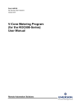
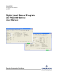
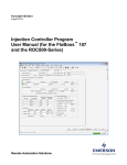
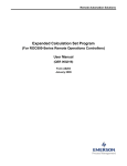
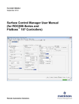
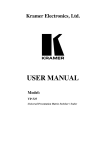
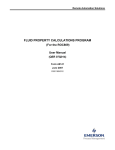
Part D301745X012 August 2014 Cause and Effect User Manual (ROC800) Remote Automation Solutions Cause and Effect Manager Program User Manual (ROC800) Revision Tracking Sheet August 2014 This manual may be revised periodically to incorporate new or updated information. The revision date of each page appears at the bottom of the page opposite the page number. A change in revision date to any page also changes the date of the manual that appears on the front cover. Listed below is the revision date of each page (if applicable): Page Initial release ii Revision August-14 Issued Aug-14 Cause and Effect Manager Program User Manual (ROC800) Contents Chapter 1 – Introduction 1.1 1.2 1.3 Scope and Organization ................................................................................................................... 1 Product Overview ............................................................................................................................. 1 Program Requirements .................................................................................................................... 2 1.3.1 License Key ......................................................................................................................... 3 Chapter 2 – Installation 2.1 2.2 Issued Aug-14 11 Effect Configuration Screen............................................................................................................ 13 Cause Configuration Screen .......................................................................................................... 16 Saving the Configuration ................................................................................................................ 24 Chapter 4 – Reference Material 4.1 4.2 5 Installing the License Key ................................................................................................................. 5 2.1.1 Verifying the License Key Installation .................................................................................. 6 Downloading the Program ................................................................................................................ 7 Chapter 3 – Configuration 3.1 3.2 3.3 1 27 Point Type 71/74: Cause Configurations ........................................................................................ 28 Point Type 72/75: Effect Configuration ........................................................................................... 34 iii Cause and Effect Manager Program User Manual (ROC800) [This page is intentionally left blank.] iv Issued Aug-14 Cause and Effect Manager Program User Manual (ROC800) Chapter 1 – Introduction Caution When implementing control using this product, observe best industry practices as suggested by applicable and appropriate environmental, health, and safety organizations. While this product can be used as A safety component in a system, it is NOT intended or designed to be the ONLY safety mechanism in that system. This chapter describes the structure of this manual and presents an overview and installation instructions of the Cause and Effect Manager Program for the ROC800-Series Remote Operations Controller. 1.1 Scope and Organization This document serves as the user manual for the Cause and Effect Manager program, which is intended for use in a ROC800-Series (ROC800). This manual describes how to download, install, and configure the Cause and Effect Manager program (referred to as the “Cause and Effect program” or “the program” throughout the rest of this manual). You access and configure this program using ROCLINK™ 800 Configuration Software (version 2.10 or greater) loaded on a personal computer (PC) running Windows® 2000 (with Service Pack 2), Windows XP (with Service Pack 3), Windows Vista™ (32-bit), or Windows 7 (32-bit). The sections in this manual provide information in a sequence appropriate for first-time users. Once you become familiar with the procedures and the software, the manual becomes a reference tool. This manual has the following major sections: Chapter 1 – Introduction Chapter 2 – Installation Chapter 3 – Configuration Chapter 4 – Reference This manual assumes that you are familiar with the ROC800 and its configuration. For more information, refer to the following manuals: ROC800 Remote Operations Controller Instruction Manual (Part D301217X012) ROCLINK 800™ Configuration Software User Manual (for ROC800Series) (Part D301250X012) 1.2 Product Overview The Cause & Effect Manager user program for the ROC800 supports up to 128 causes and 48 effects. The program is designed to allow you to configure the ROC800 to do logical operations without writing FSTs. A Cause typically monitors a selected point that would be logically evaluated against a user defined set-point. Any tripped Cause linked to an Effect forces Issued Aug-14 1 Cause and Effect Manager Program User Manual (ROC800) the action defined in that Effect. An example of this would be a gas application monitoring multiple gas quality limits defined as Causes (BTU, H2S, Nitrogen, CO2, etc) which are linked to a slam valve (which is the Effect). The layout of the configuration screens is such that you can configure logic by inputting entries from a Cause and Effect matrix. In many cases, you can input the effects and causes line by line through the entire matrix. Features Cause precondition evaluation must be satisfied before a trip is possible. Cause compound primary and secondary conditions that trips the cause based on “And / Or” evaluation. Cause operators that allow selectable evaluations or operations (logical, on-change, mathematical, watchdog and data movement). Cause condition and precondition timer delays. Cause condition deadbands. Caused definitions for up to 16 effect link assignments. Cause trips that clear automatically when the condition clears or trips that are reset controlled. Cause alarming to the ROC alarm log for trips and/or clears. Effect active/inactive values or states that are definable. Effect selectable option to assert those values continuously or not. Effect usage that defines its behavior as a normal effect or a reset point (i.e. reset push button). Effect delay timer. Effect last four tattletales that show the order of multiple causes tripped. 1.3 Program Requirements The Cause and Effect program is compatible with version 3.50 (or greater) of the ROC800 firmware and with version 2.10 (or greater) of the ROCLINK 800 software. Program specifics include: Note: 2 You must load one version of the program only depending on your available user program slot or location. The CauseAndEffect_128x48_TLP7172.tar and the CauseAndEffect_128x48_TLP7475.tar program files support 128 causes and 48 effects. The CauseAndEffect_64x32_TLP7172.tar and the CauseAndEffect_64x32_TLP7475.tar program files support 64 causes and 32 effects. Issued Aug-14 Cause and Effect Manager Program User Manual (ROC800) File Name Target Unit/ Version User Defined Point (UDP) Flash Used (in bytes) DRAM Used (in bytes) ROCKLINK 800 Version Display Number CauseAndEffect_128x 48_TLP7172.tar ROC800 3.50 71, 72 52,328 143,360 2.10 71, 72 CauseAndEffect_128x 48_TLP7475.tar ROC800 3.50 74, 75 52,328 143,360 2.10 74, 75 CauseAndEffect_64x32 _TLP7172.tar ROC800 3.50 71, 72 51,328 126,976 2.10 71, 72 CauseAndEffect_64x32 _TLP7475.tar ROC800 3.50 74, 75 51,328 126,976 2.10 74, 75 Note: You must connect a PC to the ROC800’s LOI port before starting the download. For information on viewing the memory allocation of user programs, refer to the ROCLINK 800 Configuration Software User Manual (for ROC800Series) (Part D301250X012). 1.3.1 License Key License keys, when matched with valid license codes, grant access to applications such as Cause and Effect. The term “license key” refers to the physical piece of hardware that can contain up to seven different licenses (refer to Figure 1). Each ROC800 can have none, one, or two license keys installed. If you remove a license key after enabling an application, the firmware disables the task from running. This prevents unauthorized execution of protected applications in a ROC800. J1 U1 DOC0422A Figure 1. License Key Note: The Cause and Effect program requires either Cause and Effect (for CauseAndEffect_128x48_TLP7172.tar and CauseAndEffect_128x48_TLP7475.tar program files) or C&E64X32 (for CauseAndEffect_64x32_TLP7172.tar and CauseAndEffect_64x32_TLP7475.tar program files) license key depending on your requirements. Issued Aug-14 3 Cause and Effect Manager Program User Manual (ROC800) [This page is intentionally left blank.] 4 Issued Aug-14 Cause and Effect Manager Program User Manual (ROC800) Chapter 2 – Installation This section provides instructions for installing the Cause and Effect program into the ROC800. Read Section 1.3 of this manual for program requirements. 2.1 Installing the License Key If you order the Cause and Effect program for a new ROC800, your ROC800 is delivered with the license key installed. Go to Section 2.2. If you order the program for an existing ROC800, you must install the license key yourself. Caution Failure to exercise proper electrostatic discharge precautions, such as wearing a grounded wrist strap may reset the processor or damage electronic components, resulting in interrupted operations. When working on units located in a hazardous area (where explosive gases may be present), make sure the area is in a nonhazardous state before performing these procedures. Performing these procedures in a hazardous area could result in personal injury or property damage. To install a license key: 1. Remove power from the ROC800. 2. Remove the wire channel cover 3. Unscrew the screws from the Central Processing Unit (CPU) faceplate. 4. Remove the CPU faceplate 5. Place the license key in the appropriate terminal slot (P4 or P6) in the CPU Incorrect Correct DOC0423A Figure 2. License Key Installation 6. Press the license key into the terminal unit it is firmly seated (Refer to Figure 2. 7. Replace the CPU faceplate. 8. Replace the screws on the CPU faceplate. 9. Replace the wire channel cover. 10. Restore Power to the ROC800. Issued Aug-14 5 Cause and Effect Manager Program User Manual (ROC800) 2.1.1 Verifying the License Key Installation After you install the license key, you can verify whether the ROC800 recognizes the key. From the ROCLINK 800 screen, From the ROCLINK 800 screen, select Utilities > License Key Administrator. The License Key Administrator screen displays: Figure 3. Transfer Licenses Between a Device and a Key (Cause and Effect) Figure 4. Transfer Licenses Between a Device and a Key (C&E64X32) 6 Issued Aug-14 Cause and Effect Manager Program User Manual (ROC800) 2.2 Downloading the Program This section provides instructions for installing the program into the Flash memory on the ROC800. To download the program using ROCLINK 800 software: 1. Connect the ROC800 to your computer using the LOI port. 2. Start and logon to ROCLINK 800. 3. Select Utilities > User Program Administrator from the ROCLINK menu bar. The User Program Administrator screen displays (see Figure 3): Figure 3. User Program Administrator 4. Click Browse in the Download User Program File frame. The Select User Program File screen displays (see Figure 4). 5. Select the path and user program file to download from the CD-ROM. (Program files are typically located in the Program Files folder on the CD-ROM). As Figure 4 shows, the screen lists all valid user program files with the .tar extension: Issued Aug-14 7 Cause and Effect Manager Program User Manual (ROC800) Figure 4. Select User Program File 6. Click Open to select the program file. The User Program Administrator screen displays: Figure 5. User Program Administrator 8 Issued Aug-14 Cause and Effect Manager Program User Manual (ROC800) 7. Click Download & Start to begin loading the selected programs. The following message displays: Figure 6. Confirm Download Note: If the User Display Conflict screen (Figure 7) displays when you click the Download & Start, choose another empty slot or select another program that is compatible with your license but with different TLP. See Section 1.3.1 for more information. Figure 7. User Display Conflict 8. Click Yes to begin the download. When the download completes the following message displays: Figure 7. ROCLINK 800 Download Confirmation 9. Click OK. The User Program Administrator screen displays (see Figure 8). Note that: Issued Aug-14 9 Cause and Effect Manager Program User Manual (ROC800) The User Programs Installed in Device frame identifies the installed program(s). The Status field indicates that the program is running. Figure 8. User Program Administrator 10. Click Close. The ROCLINK 800 screen displays and the download is complete. Proceed to Chapter 3, Configuration. 10 Issued Aug-14 Cause and Effect Manager Program User Manual (ROC800) Chapter 3 – Configuration Before you begin configuring causes and effects, a little planning is helpful. You can have up to 48 effects triggered by up to 128 causes. It is best to plan your effects first, and then decide what triggers them. The intersecting point in the matrix shows which causes trip which effects. It may be useful to use another symbol to show which trips reset automatically when the condition clears, and which ones need a manual reset. You may wish to use a chart shown in Figure 9 as a handy way to organize your information. Notice the effects are across the top in columns, and the causes are listed down the left side of the table for easy reference: Figure 9. Sample Matrix Issued Aug-14 11 Cause and Effect Manager Program User Manual (ROC800) To configure the program (after logging onto ROCLINK 800 and successfully installing the program), proceed through the program screens as shown in the following sections. Figure 10. ROCLINK 800 12 Issued Aug-14 Cause and Effect Manager Program User Manual (ROC800) 3.1 Effect Configuration Screen Each Effect represents a particular action that is taken when the Causes that are linked to it are tripped or cleared. The Value When Active is the value that is applied to the PtDef selected when the Effect Is Active. The Value When Inactive is the value that is applied to the PtDef selected when the Effect Is Not Active. Use the Assert Effect Continuously option to control writes to the effect point once or continuously. Writing one time to the output can be useful for operations such as setting a discrete output momentary parameter for a resettable output. The screen is divided into five main sections – Effect Configuration, Effect Usage, Effect Status, Active Link Tattletale and Effect Edit: To access this screen: 1. From the Directory Tree, select User Program > Cause and Effect Mgr. 2. Double-click #75, Effect Configuration. 3. Double-click #1, Effect 1. The Effect Configuration screen displays: Figure 11. Effect Configuration Screen Issued Aug-14 13 Cause and Effect Manager Program User Manual (ROC800) 4. Review—and change as necessary—the values in the following fields: Field Description Point Number Specifies the effect identification. Effect Configuration Use this area to name your effect, define the point and define the active and inactive states that will be applied. Tag Name Enable Effect PtDef Sets the 10-character name for the effect. If this box is checked, the effect will be processed. If unchecked, this effect will be ignored, even when a cause is linked to it. Sets the TLP to be controlled. Tag Displays the tag name of the TLP specified in the PtDef field. Cur Value Displays the current value of the TLP specified in the PtDef field. Value When Active Sets the value that is sent to the TLP defined in the PtDef field. Value When Inactive Sets the value that is sent to the TLP defined in the Effect Def field whenever the effect is un-actuated. If the field Force Value When Inactive is unchecked, the TLP defined in the PtDef field is not controlled by Value When Inactive when unactuated. Force Value When Inactive Determines if the Value When Inactive value be written to the TLP defined at PtDef when the effect is un-actuated. Assert Effect Continuously When checked, the Active or Inactive values are written to the PtDef selection continuously. This may be desirable to assure that the output is reasserted to the expected state. When unchecked, the program sets the state one time. This may be useful for a DO point in the momentary mode that must reset itself. Effect Usage This frame allows effects to be defined as reset points. Reset points are monitored by causes that require a reset before clearing from a tripped condition. 14 Normal (Not used as a reset) Choose this button when the effect is handled as a normal effect (this is the default). Hard-Wired (DI Point) Choose this when you wish the effect to behave as a reset point such as the input for a reset push button. Issued Aug-14 Cause and Effect Manager Program User Manual (ROC800) Field Description Software Reset Reset Code Choose this when you wish the effect to behave as a reset point that can be reset through a variable. This variable can then be controlled through the LCD display or set by SCADA. The program will automatically reset the field back to the Inactive Value after it is set. The program now allows the selection of other data types besides UINT8. Defines a code that if matched to a Cause Reset Code will reset those Causes when a Software or Hard-Wired reset point is detected. Multiple codes allow multiple independent resets possibilities. A reset point is normally a digital input point, such as a status point. For example, you may have the “Pt Def” configured to be a DI status and the “Actuated Value” would be the value of the digital input when the reset button is pushed. All causes that require resets (Require Reset = checked) would examine this reset effect and clear all tripped causes assuming their conditions are clear. Effect Status This area shows the effect active status and configures the effect delay. Effect Active Preset Sec Elapsed Sec Shows whether the effect has been tripped (actuated). Shows the preset in seconds that will delay the effect active action. Shows the timer in seconds showing the delay before the effect is active. Active Link Tattletale This area is informational related to tattletale order and tags. st 1 Trip = Cause # nd 2 Trip = Cause # Shows the first cause that currently holds this effect active. Shows the second cause that currently holds this effect active. rd Shows the third cause that currently holds this effect active. th Shows the fourth cause that currently holds this effect active. 3 Trip = Cause # 4 Trip = Cause # st th Tag (1 – 4 Trip) Current Active Link Count Inactive Message Shows the cause tag name. Shows the number of causes that currently activate this effect. Sets a 10 character tattletale tag message when the effect is inactive. This may be useful if the first Trip tattletale tag is displayed on the LCD and a meaningful inactive message is needed (i.e. “No Alarms”). Insert/Delete This area is used to insert or delete effects within the list. Issued Aug-14 15 Cause and Effect Manager Program User Manual (ROC800) Field Description Insert Inserts an effect before the Effect # indicated. This button is grayed out when waiting for the Effect # to be entered and applied and re-gray out after the action is taken. Multiple inserts are possible one at a time. The last effect will always roll off the end, so make sure there are unused spares at the end of the list. Delete Deletes the effect at the Effect # indicated. This button is grayed out when waiting for the Effect # to be entered and applied and re-gray out after the action is taken. Multiple deletes are possible one at a time. Indicates the effect to insert before or the effect to delete according to what action is taken. Enter the Effect # first and the Apply button next to un-gray the Insert/Delete buttons. The two step process is meant to prevent accidental inserts or deletes. It is not necessary to be in the screen showing that effect to operate on a particular Effect #. Effect # 5. Click Apply to save your changes. 6. Click Close to return to the ROCLINK 800 screen. Proceed to Section 3.2 to configure the Cause Configuration screen. 3.2 Cause Configuration Screen Causes are configured to do comparisons with a true/false result that controls effects, or configured to do math functions or timing. Other features include delay timing, dynamic enabling, and compound comparisons. You can connect individual causes to one or up to 16 effects. When the cause is true, the connected effects are actuated. The Cause Configuration window is divided into eight main sections – Cause Configuration, Pre-Condition, Primary Logic Section, Secondary Logic Section, Effect Assignments, Misc Parameters, Insert/Delete and Cause Status. To access this screen: 1. From the Directory Tree, select User Program > Cause and Effect Mgr. 2. Double-click Display #74 Cause Configuration. 3. Double-click #1, Cause 1. The Cause Configuration screen displays: 16 Issued Aug-14 Cause and Effect Manager Program User Manual (ROC800) Figure 12. Cause Configuration Screen Figure 13. Cause Configuration Screen – Compound cause selected Issued Aug-14 17 Cause and Effect Manager Program User Manual (ROC800) Figure 14. Cause Configuration Screen – Pre-Condition Required enabled 4. Review the values in the following fields: Field Description Point Number Specifies the cause identification. General Cause Configuration Configures the Cause by assigning a name for the cause, defining the cause as simple or compound, and setting whether a pre-condition is required. Tag Name Cause Enabled Simple Compound Pre-Condition Required Secondary’s Relationship with Primary 18 Sets a 10-character identification name for the selected cause. Enables the selected cause. Make sure that everything on the cause configuration screen is configured correctly before enabling the cause. Sets one logic section for the selected cause. Sets two logic sections (primary and secondary) for the selected cause. Sets a pre-condition in order to activate the cause. Sets the relationship between the primary and secondary logic sections. The two valid selections are AND with Primary and OR with Primary. This parameter shows only when Compound cause is selected. Issued Aug-14 Cause and Effect Manager Program User Manual (ROC800) Field Description Cause Execution Pre-Condition Defines the pre-condition of the selected cause. This frame shows only when the Pre-Condition Required option is activated or checked in the General Cause Configuration section. Pre-Condition Met SetPt Delay Secs Preset Elaps Sec This read-only parameter shows if the pre-condition is met or not. Sets the point where the pre-condition test commences according to the selected operator. The operator selection is located on the left side of the to select the operator. Valid StPt field. Click operators are == (equal), >= (greater than or equal to), != (not equal), and <= (less than or equal to). Sets the time for the system to wait after the condition is met before activating the cause. This read-only parameter shows the elapsed time in seconds. Primary Logic Section Defines and Configures the Primary logic of the selected cause. PtDef Sets the TLP that displays in Cur Value. This item can be any numerical point in the ROC including to browse values from other Causes. Click through the list of available parameters. Tag Displays the tag name of the TLP specified in the PtDef field. Cur Value Operator Displays the current value of the TLP specified in the PtDef field. Sets the Cur Value and SetPt Value comparison operator. Click to select the operator. Avaliable operators are as follows: >= True if greater than or equal to <= True if less than or equal to == True if equal to != True if not equal to One-Scan Rising Cur Value, 0 to 1 transition = true One-Scan Falling Cur Value, 1 to 0 transition = true Watchdog Timer Resets on changing value of Cur Value On-Change Detects a change in the value. Can monitor a DI accumulator to capture a brief pushbutton press. Note: The On-Change operator always needs a Required Reset configured to clear the Cause trip condition. Issued Aug-14 19 Cause and Effect Manager Program User Manual (ROC800) Field Description Copy Data Add Subtract Multiply Divide Modulus 20 Copies from PtDef to SetPt Value. There are four different types of copies – by logicals, by parameters, logicals to parameters, parameters to logicals. The numeric value in the DeadBand field to tells the system what type of copy to make and how much data to copy. Number Copy Type Logicals XX Source data located in a Logical order will be copied to the Target data location in a Logical order. Parameters 1XX Source data located in a Parameter order will be copied to the Target data location in a Parameter order. Logicals to 2XX Parameters Source data located in a Logical order will be copied to the Target data location in a Parameter order. Parameters to 3XX Logicals Source data located in a Parameter order will be copied to the Target data location in a Logical order. For example, 105 in the DeadBand field means copy parameters 0 through 4 to parameters 1 through 5 on another TLP. Cur Value plus the SetPt Value Cur Value minus the SetPt Value Cur Value times the SetPt Value Cur Value divided by the SetPt Value Integer remainder of Cur Value / SetPt Value. Issued Aug-14 Cause and Effect Manager Program User Manual (ROC800) Field Description SetPt Def Sets the TLP of the set point value dynamic source. Click to browse through the list of available parameters. SetPt Value Holds the value that is used for comparisons and math functions. This field is not used for the OneScan or Watchdog Timer functions. If the SetPt Def field is configured (other than “Undefined”), this field gets its value from the TLP specified in SetPt Def. Deadband or Math Result This field serves three purposes. When using comparison operators (>=, <=, ==, !=), it specifies a dead band value that must be exceeded before an existing true comparison can go false. For math functions (Add, Subtract, Multiply, Divide), this field holds the result of the math operation. For the Copy Data function, this field defines the number of fields or parameters to copy. DeadBand is not used with One-Scan or Watchdog Timer functions. Preset Secs Sets the number of user-defined seconds for which the comparison must be true before the cause goes true. The exception is if Trip While Timer Is Timing is selected, the cause will be true during the timer period. Elapsed Secs Displays the delay count in seconds up to the userdefined preset. When the comparison becomes true, the count (seconds) increments until it reaches the “Preset Secs” and the cause becomes true. If at any time the comparison turns false, the count resets to zero and the cause becomes false. The exception is if Trip While Timer Is Timing is selected, the cause will be true during the timer period. Timer Timing Indicates that the timer has been activated. Trip While Timer is Timing Secondary Logic Section When the cause condition is met, this selection when checked, trips the cause while the timer is timing. The cause clears when the timer expires. This setting is normally used without a Required Reset. Defines and Configures the Secondary logic of the selected cause. This section shows only if Compound is selected in the General Cause Configuration frame. The Secondary Logic section has the same fields and logic as the Primary Logic section. Effect Assignments Links the Cause to one or more Effects. # of Link ( 1-16) # Links Currently Active Issued Aug-14 Sets the first, second, third (and so on) effect to be activated. For instance, if you wanted effect number 4 to be the first to activate, then enter 4 in the # of Link 1 field. Shows the number of effects that are currently tripped for the cause. 21 Cause and Effect Manager Program User Manual (ROC800) Field Description Misc Parameters Allows cause logging and enables cause resetting. Log Trips Determines if an alarm generated by the cause will be written to the ROC’s alarm log. If this field is checked, every time the cause is tripped an alarm will be logged. The log consists of the cause’s 10character tag and the value of Cur Value along with the date and time. Require Reset? Check this box if the logic requires that a reset button needs to be pushed before the cause is set back to false. This is normally used in scenarios when the cause goes true it actuates effects that cause a shutdown and it is desired that the shutdown be maintained until a manual reset. Log Clears Determines whether an entry will be written to the ROC’s alarm log when this cause is cleared. If this field is checked, every time the cause is cleared an alarm will be logged. The log consists of the cause’s 10-character tag and the value of Cur Value along with the date and time. Note: Log entries that begin with a “Z” as the first digit are cause entries. Alarms not generated by Cause & Effect are not prefixed with a Z. Sets a numeric value that is associated with the Effect Reset Code, providing the reset through a button or software point. By using multiple codes, many independent resets are possible. Reset Code Minimum Trip Secs Preset Elaps Trip Secs. Accumulated Trips Holds the trip state for a minimum time so a short duration trip can be detected. Shows the minimum trip timer. Shows the number of times the cause has been tripped. Insert /Delete Edits the cause list to avoid manually retyping all the cause parameters when a shift is needed. 22 Insert Inserts a cause before the cause # indicated. This button is grayed out when waiting for the Effect # to be entered and applied and re-gray out after the action is taken. Multiple inserts are possible one at a time. The last cause always rolls off the end, so make sure there are unused spares at the end of the list. Delete Deletes the cause at the Cause # indicated. This button is grayed out when waiting for the Effect # to be entered and applied and re-gray out after the action is taken. Multiple deletes are possible one at a time. Issued Aug-14 Cause and Effect Manager Program User Manual (ROC800) Field Cause # Description Sets the cause to insert before or the cause to delete according to what action is taken. Enter the Cause # first and the Apply button next to un-gray the Insert/Delete buttons. The two step process is meant to prevent accidental inserts or deletes. It is not necessary to be in the screen showing that cause to operate on a particular Cause #. Cause Status Indicates the Status of the Cause. Red indicates tripped, and green indicates not tripped. Pre-Condition Met Shows whether the Pre-Condition section has been tripped (1 for Yes, 0 for No). Primary Section Tripped Shows whether the Primary section has been tripped (1 for Yes, 0 for No). Secondary Section Tripped Shows whether the Primary section has been tripped (1 for Yes, 0 for No). Cause Tripped Shows whether the cause has been tripped (1 for Yes, 0 for No). If this is a compound cause and the relationship between primary and secondary was set to AND, the cause will only be tripped if both the Primary Section and Secondary Sections are tripped. 5. Click Apply to save any changes you have made to this screen. 6. Click Close to return to the ROCLINK 800 screen. Proceed to Section 3.3 to save the configuration. Issued Aug-14 23 Cause and Effect Manager Program User Manual (ROC800) 3.3 Saving the Configuration Whenever you modify or change the configuration, it is a good practice to save the final configuration to memory. To save the configuration: 1. Select ROC > Flags. The Flags screen displays: Figure 15. Flags screen 2. Click Save Configuration. A verification message displays: Figure 16. Perform screen 3. Click Yes to begin the save process. The Flash Write Status field on the Flags screen displays In Progress. When Save Configuration is complete, the Flash Write Status field on the Flags screen displays Completed. 24 Issued Aug-14 Cause and Effect Manager Program User Manual (ROC800) 4. Click Update on the Flags screen. This completes the process of saving your new configuration. Note: For archive purposes, you should also save this configuration to your PC’s hard drive or a removable media (such as a flash drive) using the File > Save Configuration option on the ROCLINK 800 menu bar. Issued Aug-14 25 Cause and Effect Manager Program User Manual (ROC800) [This page is intentionally left blank.] 26 Issued Aug-14 Cause and Effect Manager Program User Manual (ROC800) Chapter 4 – Reference Material This section provides tables of information on the operation of the program and the user-defined point types used by the Cause and Effect program. For Cause and Effect large versions (Cause and Effect regular license) Point Type 71/74 (Cause Configuration) Point Type 72/75 (Effect Configuration) For Cause and Effect small versions (C&E64X32 license) Issued Aug-14 Point Type 71/74 (Cause Configuration) Point Type 72/75 (Effect Configuration) 27 Cause and Effect Manager Program User Manual (ROC800) 4.1 Point Type 71/74: Cause Configurations Point type 71/74 contains the parameters for configuring the Cause. The program maintains either sixty-four or one-hundred-twenty-eight logical points for this point type. Point Type 71/74: Cause Configuration Parm # Name Access System or User Update Data Type Length 0 Cause Tag R/W User AC10 10 1 Enable Cause R/W User UINT8 1 Range 0x20 → 0x7E for each ASCII characters 0→1 Description of functionality and meaning of values Default Version Cause 1 to Cause 128 1.31 Indicates cause tag name. 0 1.31 Enables the Cause. 0 = Disable 1= Enable 2 R/W User TLP 3 0,0,0 1.31 Selects the primary logic current. Selects the gas meter to be used. 3 Input1 Tag R/O System AC10 1 0x20 → 0x7E for each ASCII characters 1 1.31 4 Cur Value 1 R/W System FLOAT 4 Any Floating Number 0 1.31 Shows the primary logic current value. 5 Function1 Type R/W User UNIT8 1 1, 2, 3, 4, 5, 7, 8, 9, 10, 11, 12, 13, 14, 18 1 1.31 Selects the primary logic operator. 1. >= 2. <= 3. == 4. != 5. Watch Dog Timer 7. One Scan Rising 8. One Scan Falling 10. Add 11. Subtract 12. Multiply 13. Divide 14. Modulus 18. Copy Data 6 SetPt1 Definition R/W User TLP 3 0,0,0 1.31 Sets the primary logic setpoint selection 0 1.31 Sets primary logic setpoint value 7 28 Input1 Definition SetPt1 Value R/W User FLOAT 4 Any Floating number Issued Aug-14 Cause and Effect Manager Program User Manual (ROC800) Point Type 71/74: Cause Configuration Parm # Name Access System or User Update Data Type Length Range Default Version Description of functionality and meaning of values 8 Deadband or Result1 R/W User FLOAT 4 Any Floating number 0 1.31 Sets primary logic setpoint deadband or math result 9 Part2 Enable R/W User UNIT8 1 0→1 0 1.31 Enables Secondary. 0 = Simple 1 = Compound 10 Input2 Definition R/W User TLP 3 0,0,0 1.31 Selects secondary logic point. 11 Input2 Tag R/O System UINT8 1 0x20 → 0x7E for each ASCII character 1.31 Sets secondary logic point tag ID. 12 Current Value2 R/O System FLOAT 4 Any Floating number 0 1.31 Sets secondary logic current value. 13 Function2 Type R/W User UNIT8 1 1, 2, 3, 4, 5, 7, 8, 9, 10, 11, 12, 13, 14, 18 1 1.31 Selects the primary logic operator. 1) >= 2) <= 3) == 4) != 5) Watch Dog Timer 7) One Scan Rising 8) One Scan Falling 10) Add 11) Subtract 12) Multiply 13) Divide 14) Modulus 18) Copy Data 14 SetPt2 Definition R/W User TLP 3 0,0,0 1.31 Sets the primary logic setpoint. 15 SetPt2 Value R/W User FLOAT 4 Any Floating number 0 1.31 Sets primary logic setpoint value. 16 Deadband or Result2 R/W User FLOAT 4 Any Floating number 0 1.31 Sets primary logic setpoint deadband or math result. 17 And/Or Mode R/W User UINT8 1 15 → 16 15 1.31 Sets Secondary relationship with Primary. 15 = And with Primary 16 = Or with Primary Issued Aug-14 29 Cause and Effect Manager Program User Manual (ROC800) Point Type 71/74: Cause Configuration Parm # Name Access System or User Update Data Type Length Range Default Version Description of functionality and meaning of values 18 Cause Trip/Clear R/O System UINT8 1 0→1 0 1.31 Shows Cause Tripped status. 0 = No 1 = Yes 19 Part1 Trip/Clear R/O System UINT8 1 0→1 0 1.31 Shows Primary Section Tripped status. 0 = No 1 = Yes 20 Part2 Trip/Clear R/O System UINT8 1 0→1 0 1.31 Shows Secondary Section Tripped status. 0 = No 1 = Yes 21 Use Digital Enabler R/W User UINT8 1 0→1 0 1.31 Enables pre-condition required. 0 = Disable 1 = Enable 30 22 Digi Enab Definition R/W User TLP 3 0,0,0 1.31 Sets the pre-condition point type. 23 Digi Enab Tag R/O System AC10 10 0x20 → 0x7E for each ACII character 1.31 Sets the pre-condition point tag ID. 24 Digi Enab Process Value R/O System FLOAT 4 Any Floating number 0.0 1.31 Sets the pre-condition point value. 25 Digi Enabler Type R/W User UINT8 1 0→3 0 1.31 Sets the pre-condition operator. 0) == 1) != 2) >= 3) <= 26 Digi Enab StPt Value R/W User FLOAT 4 Any Floating number 0.0 1.31 Sets pre-condition setpoint. 27 Digi Enab Result Status R/O System UINT8 1 0→1 0 1.31 Shows if the pre-condition met. 28 Enab Delay Secs Preset R/W User UINT16 2 0 → 65535 30 1.31 Sets the pre-condition timer in seconds. 29 Enab Delay Secs Elapsed R/O System UINT16 2 0 → 65535 0 1.31 Shows the pre-condition timer in seconds. 0 = No 1 = Yes Issued Aug-14 Cause and Effect Manager Program User Manual (ROC800) Point Type 71/74: Cause Configuration Parm # Name Access System or User Update Data Type Length Range Default Version Description of functionality and meaning of values 30 Pri Trip Delay Secs Preset R/W User UINT16 2 0 → 65535 0 1.31 Sets the Primary Logic Trip Preset in seconds. 31 Pri Trip Delay Secs Elapsed R/O System UINT16 2 0 → 65535 0 1.31 Shows the Primary Logic Trip Elapsed in seconds. 32 Scan Interval R/W User UINT8 1 0→5 3 1.31 Sets the scan interval. (Not Used) 0 = 100 ms 1 = 200 ms 2 = 500 ms 3=1s 4=2s 5=5s 33 Log Alarms R/W User UINT8 1 0→1 0 1.31 Activates the Alarm Log 1 = No 1 = Yes 34 Require Reset R/W User UINT8 1 0→1 0 1.31 Sets if Trip requires reset 1 = No 1 = Yes 35 Effect1 R/W User UINT8 1 1→8 0 1.31 Sets Effect assignment link 1 36 Effect2 R/W User UINT8 1 1→8 0 1.31 Sets Effect assignment link 2 37 Effect3 R/W User UINT8 1 1→8 0 1.31 Sets Effect assignment link 3 38 Effect4 R/W User UINT8 1 1→8 0 1.31 Sets Effect assignment link 4 39 Effect5 R/W User UINT8 1 1→8 0 1.31 Sets Effect assignment link 5 40 Effect6 R/W User UINT8 1 1→8 0 1.31 Sets Effect assignment link 6 41 Effect7 R/W User UINT8 1 1→8 0 1.31 Sets Effect assignment link 7 42 Effect8 R/W User UINT8 1 1→8 0 1.31 Sets Effect assignment link 8 43 Links Energized R/O System UINT8 1 1→8 0 1.31 Indicates if the Effects assignment links are currently active. 44 Min Trip Secs Preset R/W User UINT16 2 0 → 65535 0 1.31 Sets the minimum trip in seconds preset. 45 Min Trip Secs Elapsed R/O System UINT16 2 0 → 65535 0 1.31 Issued Aug-14 Sets the minimum trip in seconds elapsed. 31 Cause and Effect Manager Program User Manual (ROC800) Point Type 71/74: Cause Configuration Parm # 46 Name Log Clears Access System or User Update Data Type Length Range Default Version R/W User UINT8 1 0→1 0 1.31 Description of functionality and meaning of values Enables logs clears to alarm log. 0 = No 1 = Yes 47 Reset Code R/W User UINT8 1 0 → 255 0 1.31 Sets reset code to match with effect reset code. 48 Sec Trip Delay Secs Preset R/W User UINT16 2 0 → 65535 0 1.31 Sets the secondary trip preset in seconds 49 Sec Trip Delay Secs Elapsed R/O User UINT16 2 0 → 65535 0 1.31 Sets the secondary trip elapsed in seconds 50 Pri Trip Delay Timer Timing R/O System UINT8 1 0→1 0 1.31 Sets the primary logic trip timer timing. Sec Trip Delay Timer Timing R/O 52 Accumulated Trips R/W Both UINT16 2 0 → 65535 0 1.31 Shows accumulated trips 53 Pri Trip When Timer Timing R/W User UINT8 1 0→1 0 1.31 Sets the secondary trip when timing timer. Sec Trip When Timer Timing R/W 55 Effect 9 R/W User UINT8 56 Effect 10 R/W User UINT8 57 Effect 11 R/W User UINT8 58 Effect 12 R/W User UINT8 59 Effect 13 R/W User UINT8 60 Effect 14 R/W User 61 Effect 15 R/W 62 Effect 16 R/W 51 54 32 0 = Timer expired 1 = Timing System UINT8 1 0→1 0 1.31 Sets the secondary logic trip timer timing. 0 = Timer expired 1 = Timing 0 = Normal 1 = Trip when timer timing User UINT8 1 UINT8 0 1.31 Sets the primary trip when timing timer. 0 = Normal 1 = Trip when timer timing UINT8 0 1.31 Sets the Effect assignment link 9. 1 UINT8 0 1.31 Sets the Effect assignment link 10. 1 UINT8 0 1.31 Sets the Effect assignment link 11. UINT8 0 1.31 Sets the Effect assignment link 12. 1 UINT8 0 1.31 Sets the Effect assignment link 13. UINT8 1 UINT8 0 1.31 Sets the Effect assignment link 14. User UINT8 1 UINT8 0 1.31 Sets the Effect assignment link 15. User UINT8 1 UINT8 0 1.31 Sets the Effect assignment link 16. Issued Aug-14 Cause and Effect Manager Program User Manual (ROC800) Point Type 71/74: Cause Configuration Parm # 63 Name Watchdog Timer Access System or User Update Data Type Length Range Default Version R/O System UINT16 2 0 → 65535 0 13.2 Description of functionality and meaning of values Provides an incrementing counter, to validate the program’s running status. Only updated for the first logical instance. Issued Aug-14 33 Cause and Effect Manager Program User Manual (ROC800) 4.2 Point Type 72/75: Effect Configuration Point type 72/75 contains the parameters for configuring the Effects. The program maintains either thirty-two or sixty-four logical points for this point type, depending on the version of the program installed. Point Type 72/75: Effect Configuration Parm # Name Access System or User Update Data Type Length Range Default Version Description of functionality and meaning of values 0 Effect Tag R/W User AC10 10 0x20 → 0x7E for each ASCII character Effect 1 to Effect 64 1.31 Sets the Effect tag name 1 Effect Enable R/W User UINT8 1 0→1 0 1.31 Enables effect. 0 = Disabled 1 = Enabled 2 Effect Definition R/W User TLP 3 0,0,0 3 Definition Tag R/O System AC10 10 0x20 → 0x7E for each ASCII character 4 Now Active R/O System UINT8 1 0→1 0 1.31 Selects the Effect point type. 1.31 Shoes the Point tag ID of the selected Effect. 1.31 Indicates the Effect status. 0= No 1 = Yes 5 Cur Val R/O System FLOAT 4 Any Floating Number 0.0 1.31 Shows the Effect current value. 6 Value When Active R/W User FLOAT 4 Any Floating Number 0.0 1.31 Sets Effects value when active. 7 Value When Not Active R/W User FLOAT 4 Any Floating Number 0.0 1.31 Sets Effects value when not active. 8 Apply When Not Active R/W User UINT8 1 0→1 1 1.31 Forces Values to apply when inactive. 0 = No 1 = Yes 9 Is Reset Pt? R/W User UINT8 1 0→2 0 1.31 Sets the Reset type. 0 = Not a reset point 1 = Hard-wired reset 2 = Software reset 34 Issued Aug-14 Cause and Effect Manager Program User Manual (ROC800) Point Type 72/75: Effect Configuration Parm # 10 Name 1st Out Cause Access System or User Update Data Type Length Range Default Version R/O System UINT8 1 0→1 0 1.31 Description of functionality and meaning of values Indicates first cause number tattletale. 0 = none 1 = active 11 2nd Out Cause R/O System UINT8 1 0→1 0 1.31 Indicates second cause number tattletale. 0 = none 1 = active 12 3rd Out Cause R/O System UINT8 1 0→1 0 1.31 Indicates third cause number tattletale. 0 = none 1 = active 13 4th Out Cause R/O System UINT8 1 0→1 0 1.31 Indicates fourth cause number tattletale. 0 = none 1 = active 14 1st Out Tag R/O System AC10 10 0x20 → 0x7E for each ASCII character <none> 1.31 Shows first Trip Cause Tag. 15 2nd Out Tag R/O System AC10 10 0x20 → 0x7E for each ASCII character <none> 1.31 Shows second Trip Cause Tag. 16 3rd Out Tag R/O System AC10 10 0x20 → 0x7E for each ASCII character <none> 1.31 Shows third Trip Cause Tag. 17 4th Out Tag R/O System AC10 10 0x20 → 0x7E for each ASCII character <none> 1.31 Shows fourth Trip Cause Tag. 18 Reset Code R/W User UINT8 1 0 → 255 0 1.31 Matches reset code with cause reset code. 19 Active Link Count R/O System UINT8 1 0 → 16 0 1.31 Shows current active link count. Issued Aug-14 35 Cause and Effect Manager Program User Manual (ROC800) Point Type 72/75: Effect Configuration Parm # 20 Name Assert Effect Continuously Access System or User Update Data Type Length Range Default Version R/W User UINT8 1 0→1 0 1.31 Description of functionality and meaning of values Sets wether to assert effect once or continuously. 0 = Once 1 = Continuously 21 Active Effect Delay (Sec) R/W User UINT16 2 0 → 65535 0 1.31 Sets active effect delay in seconds 22 Active Effect Timer (Sec) R/O System UINT16 2 0 → 65535 0 1.31 Sets active effect timer in seconds 23 Tattletale Inactive Message R/W User AC10 10 0x20 → 0x7E for each ASCII character <none> 1.31 Sets Tattletale inactive message. 24 Insert/Delete Edit Command R/W Both UINT8 1 0→4 0 1.31 Allows insert/delete edit command. Insert/Delete Edit Item R/W 25 36 0 = No command 1 = Effect insert 2 = Effect delete 3 = Cause insert 4 = Cause delete Both UINT8 1 0, 1 → 64 for Causes, 1 → 32 for Effects 0 1.31 Allows insert/delete edit item. Issued Aug-14 Cause and Effect Manager Program User Manual (ROC800) [This page is intentionally left blank.] Issued Aug-14 37 Cause and Effect Manager Program User Manual (ROC800) Headquarters: Emerson Process Management Remote Automation Solutions 6005 Rogerdale Road Houston, TX 77072 U.S.A. T +1 281 879 2699 | F +1 281 988 4445 www.EmersonProcess.com/Remote Europe: Emerson Process Management Remote Automation Solutions Emerson House Unit 8, Waterfront Business Park Dudley Road, Brierly Hill Dudley UK DY5 1LX T +44 1384 487200 | F +44 1384 487258 www.EmersonProcess.com/Remote North American/Latin America: Emerson Process Management Remote Automation Solutions 6005 Rogerdale Road Houston TX USA 77072 T +1 281 879 2699 | F +1 281 988 4445 www.EmersonProcess.com/Remote Middle East/Africa: Emerson Process Management Remote Automation Solutions Emerson FZE P.O. Box 17033 Jebel Ali Free Zone – South 2 Dubai U.A.E. T +971 4 8118100 | F +971 4 8865465 www.EmersonProcess.com/Remote Asia-Pacific: Emerson Process Management Remote Automation Solutions 1 Pandan Crescent Singapore 128461 T +65 6777 8211| F +65 6777 0947 www.EmersonProcess.com/Remote Remote Automation Solutions © 2014 Remote Automation Solutions, a business unit of Emerson Process Management. All rights reserved. Remote Automation Solutions, a business unit of Emerson Process Management, shall not be liable for technical or editorial errors in this manual or omissions from this manual. REMOTE AUTOMATION SOLUTIONS MAKES NO WARRANTIES, EXPRESSED OR IMPLIED, INCLUDING THE IMPLIED WARRANTIES OF MERCHANTABILITY AND FITNESS FOR A PARTICULAR PURPOSE WITH RESPECT TO THIS MANUAL AND, IN NO EVENT SHALL REMOTE AUTOMATION SOLUTIONS BE LIABLE FOR ANY INCIDENTAL, PUNITIVE, SPECIAL OR CONSEQUENTIAL DAMAGES INCLUDING, BUT NOT LIMITED TO, LOSS OF PRODUCTION, LOSS OF PROFITS, LOSS OF REVENUE OR USE AND COSTS INCURRED INCLUDING WITHOUT LIMITATION FOR CAPITAL, FUEL AND POWER, AND CLAIMS OF THIRD PARTIES. Emerson Process Management Ltd, Remote Automation Solutions (UK), is a wholly owned subsidiary of Emerson Electric Co. doing business as Remote Automation Solutions, a business unit of Emerson Process Management. FloBoss, ROCLINK, ControlWave, Helicoid, and OpenEnterprise are trademarks of Remote Automation Solutions. AMS, PlantWeb, and the PlantWeb logo are marks owned by one of the companies in the Emerson Process Management business unit of Emerson Electric Co. Emerson Process Management, Emerson and the Emerson logo are trademarks and service marks of the Emerson Electric Co. All other marks are property of their respective owners. The contents of this publication are presented for informational purposes only. While every effort has been made to ensure informational accuracy, they are not to be construed as warranties or guarantees, express or implied, regarding the products or services described herein or their use or applicability. Remote Automation Solutions reserves the right to modify or improve the designs or specifications of such products at any time without notice. All sales are governed by Remote Automation Solutions’ terms and conditions which are available upon request. Remote Automation Solutions does not assume responsibility for the selection, use or maintenance of any product. Responsibility for proper selection, use and maintenance of any Remote Automation Solutions product remains solely with the purchaser and end-user.