1
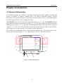
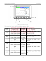
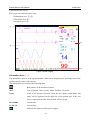
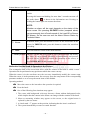
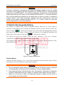
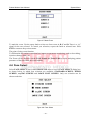
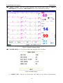
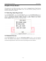
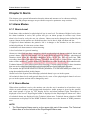
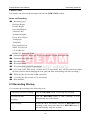
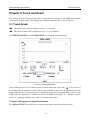
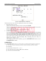
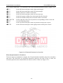
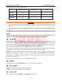
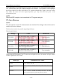
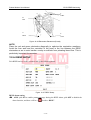
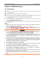
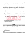
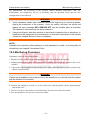
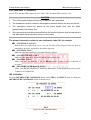
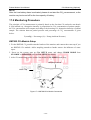
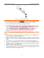
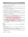
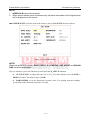
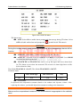
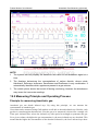
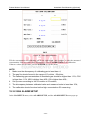
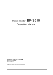
Patient Monitor User Manual
Introduction
Chapter 3 Introduction
3.1 General Information
The monitor integrates the functions of parameter measurement module, display, recording and
output to compose a compact, portable device. Its built-in replaceable battery provides
convenience for patient movement. On the high-resolution display screen, 7 waveforms and all
the monitoring parameters can be displayed clearly.
The POWER switch is on the left of the front panel (Figure 3-1, 3-2 ①). The POWER indicator
lights when the monitor is powered on (Figure 3-1, 3-2 ②). The CHARGE indicator shows the
charging status (Figure 3-1, 3-2 ③). The ALARM indicator flashes when the alarm is triggered
(Figure 3-1, 3-2 ④). The sockets of various sensors are on the left panel. Other sockets and the
power plug-in are on the rear panel. The recorder is on the right panel.
The monitor is a user-friendly device with operations conducted by a few buttons and a rotary
knob on the front panel (Figure 3-1, 3-2 ⑤⑥). Refer to Section 3.3 Button Functions.
④
②
Power
Main
Freeze
Silence
Start
Record
Menu
Charge
①
③
⑤
Figure 3-1 M9 Patient Monitor
- 11 -
⑥