1
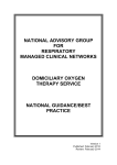
Video intercom system
Outdoor Station DPC-53x
User’s MANUAL
Contents
1. Introduction of the system and parts………………………………….. 1
2. Main feature and electronic parameter…………………………………………… 1
3. Sketch, installation dimension and notices of installation……………………….. 2
4. Operation Instruction…………………………………………………….. 3
5. Open door by IC/ID card ………………………………………………… 6
6. Methods of set outdoor station parameter………………………………….. 6
7. System parameter setup of outdoor station …………………………………. 8
8. Management parameter setup of outdoor station……………………………. 9
9. Equipment parameter setup of outdoor station……………………………… 10
10. Access parameter setup of outdoor station………………………………….. 12
11. Card management………………………………………………………………… 12
12. Programming room number online………………………………………… 13
13. Process instruction of system debugging………………………………………… 14
1 Introduction of System and Parts
Outdoor station is public parts of intercom systems at entrance or exit of buildings. The main features
are as below:
1)
Outdoor station can call and talk with all indoor monitors in this block. Outdoor station can accept
the command of indoor monitor and unlock the electronic lock in this block.
2)
Outdoor station can call and talk guard center , and transmit images to guard center at the same time
(In video frequency network), and also can require guard center to unlock or provide other services.
3)
Input correct password to unlock electronic lock. Can set two passwords to unlock door and can
change password conveniently and termly.
4)
Can unlock by using IC card.
2 Main feature and electronic parameter
1)
2)
Power supply: DC 15~18V
(Static current: 100mA; Working current: 500mA)
Environment temperature: -10~50℃
3)
Camera cell: 380TV lines, 1/3 inch CCD camera
4)
Camera lens: F=2 (focus by hand), 78 degree horizontal visual angle, 0.1 Lux
5)
Night vision: Infrared (six IR-LED)
6)
Video signal: CCIR standard, 1Vp-p range, 75Ω impedance
7)
Card type: IC card or ID card
8)
Card capacity: 500 sheets
9)
Method of adding card: operate by outdoor station keyboard or by computer
10) Keeping data times: 10 years (Not lose data when power is broken off)
11) Window of reading card: Share with display screen)
12) Audio output power: 0.8W (can adjust volume)
13) Audio frequency response: 300~3,400Hz
14) Audio transmit: among line, full duplex
15) Network cable type: RS-485 (card function do not need to be set extra cable)
16) Network cable distance: 2 kilometers (use twisted pair shielded cable)
1
Mounting
2
4. Operation Instruction
1). Call Units
a)
Under standby state, input correct room number and system will call corresponding room automatically.
For example, the second floor and room 1, please input 0201. The twelfth floor and room 8 please input
1208. Press
* to clear wrong number and input correct room number again.
b)
Press 0 + # to call the room which is called last time.
c)
Outdoor station has a “DI” bell when it is connected with room.
d)
If the indoor monitor do not hang up or do not have this number, it will be shown no the screen and can
not connect.
e)
When connect room and the user does not pick up the handset, display calling process and ring “DI”
bell.
f)
The indoor monitors which are called can display visitor image clearly, and can communicate with the
visitor after pick up the handset. And the same time, outdoor station show duration of communication
until hang up the handset or press
g)
Press
Unlock
*
on outdoor station to clear.
button to open the electronic lock, Please come in was shown on outdoor station and
it means the door is unlocked.
h)
The communication time 90 seconds, if overtime the system will shut off communication automatically
and outdoor station return to standby condition.
2) Under common password mode, unlock by password.
a) When outdoor station is under standby condition, press # button and outdoor station shows
Please input password , remind to input password to unlock the door.
b) Input 4 digital number unlock password.
c) If the password is correct, outdoor station show Please come in and it means unlocked.
d) If the password is wrong, outdoor station show Wrong password and unlock failed.
e) If input wrong password three times in 100 seconds, the system will forbid unlocking by password
100 seconds. Unlocking by password again, it will show Cancel unlocking by password. After
3
100 seconds, you can continue to use unlocking by password function.
3) Under user password mode, unlock by password
e
Please refer to the section of administration parameter setting to know how to choose
common password mode (default) and user password mode.
a) When outdoor station is under standby condition, press # button and show Please input room
number , and show lock icon on top right corner, remind you input room number to unlock.
b) Input correct room number and then show Please input password, remind to input user password.
c) If the password is right, Please come in was shown on outdoor station. It means the lock is
unlocked.
d) If the password is wrong, Wrong password was shown on outdoor station and refuses to unlock.
e) User can update the password (4 digital number), operation process as below:
1)
When outdoor station is under standby condition, press
#
button and show Please input
room number , and show lock icon on top right corner, remind you input room number.
2)
Input correct room number and will show Please input password, then press
#
and will
show Please input original password and remind to input original password. (When set user
password first time, original password is set as one group of common unlock password, refer
to parameter setup.)
3)
Input correct user password and show Please input original password, remind to input new
user password, after finish it, show Input new password again. Remind to input new user
password again. And then return to standby condition.
4)
If operation is wrong or overtime will show Wrong password, remind wrong operation and
return to standby condition.
5) If input wrong password three times in 100 seconds, the system will forbid unlocking by
password 100 seconds. Unlocking by password again, it will show Cancel unlocking by
4
password. After 100 seconds, you can continue to use unlocking by password function.
4) Call guard center
a)
Press
0000
when outdoor station is under standby condition and show Calling guard center,
remind in process of connecting guard center.
b)
If guard center is busy or refuse communication, system will show System is busy, Please call later.
It means the line is busy and return to standby condition. Please call later.
c)
If guard center be picked up, outdoor station will show communication time, limit time is 60
seconds.
d)
If over 30 seconds guard center do not pick up, outdoor station will shut off calling automatically
and return to standby condition.
e)
Press
*
to quit calling guard center and return to standby condition.
f)
Above operation base on outdoor stations are network type. If not, it is no use when press
and show Not network type, return to standby condition.
5
0000
5
Open door by IC/ID card (not support all types)
1)
Put card near display window 2~5CM (the distance is different from IC and ID card) when outdoor
station under standby condition. If your card is authorized to open this door, outdoor station will
show com in Please, remind the electronic lock is unlocked.
2)
If your card is not authorized or authorization is overdue, outdoor station will show Invalid Card,
remind this card can not unlock the door.
6
How to set outdoor station parameter
There are too many contents during setting outdoor station, so please read this manual
carefully before any setup for this system to avoid any mistakes.
1) Setup content of outdoor station including types as below:
a)
System parameter setup: For Debugging engineer only, including the type of system configure, running
parameter and so on.
b)
Management parameter setup: Manager take charge of setup and amend, including unlock password
and other items.
c)
Equipment parameter setup: For Debugging engineer only,, including the number of extension indoor
monitors, the channels of outdoor station chosen and so on.
d)
Access parameter setup: For Debugging engineer only, including address of access network, clock setup
and so on.
e) Card management setup: manager take charge of setup, including adding card or cancel card (can be
operated by computer).
2) First, should find out the password sorts of outdoor station and use occasion.
a)
Debugging password: 8 digits, which is handled by debugging engineer and used for setup system
parameter.
b)
Management password: 8 digits, which is handled by manager people when system operate and used
for setup management parameter.
Debugging and management password can be changed. Please contact supplier If forget debugging
password.
Default Debugging password is 66666666 and management password is 88888888
6
Remark: Please change password in time to avoid others access system and confuse the system.
3) How to enter into setup state
a) System under standby condition:
1) Enter into system parameter setup: press
#
and show Please input password, input
8001
and show Please input password, after input correct 8 digit debugging password, show System
parameter and enter into system parameter setup.
2) Enter into management parameter setup: press
#
and show Please input password, input
8002 and show Please input password, after input correct 8 digit management password, show
Management parameter and enter into management parameter setup.
3) Enter into equipment parameter setup: press
#
and show Please input password, input
8005
and show Please input password, after input correct 8 digit debugging password, show Equipment
parameter and enter into equipment parameter setup.
4) Enter into access parameter setup: press
#
and show Please input password, input
8006
and show Please input password, after input correct 8 digit debugging password, show Access
parameter and enter into access parameter setup.
5) Enter into card management setup: press
#
and show Please input password, input
8007
and show Please input password, after input correct 8 digit management password, show Card
management and enter into card management setup.
Remarks: The priority of debugging password is higher than management password.
Management password can be replaced by
Debugging password .
b) System under debugging condition:
System work at debugging condition, show Debugging mode, Please refer to debugging function and
option section in this manual. Under debugging condition, omit process of password input, facilitate
needed time.
4) Special remind on operation
a)
Under parameter mode, press
b)
Input digit number directly to set up.
c)
d)
e)
Setup successful, show
Setup failed, show
Press
*
#
to turn down pages and choose setup option.
.
.
to exit setup.
7
7. System parameter setup of outdoor station
Parameter
No.
Setup item
Setup instruction
Default
Set network address of outdoor station, address can not
8001-01
NET ADD
be same and address code is 3 bits. You can set scale
No
from 001 to 120.
If only one outdoor station, set as 0; if more, main control
8001-02
MULTI MODE
outdoor station should be set as 1 and another ones are
0
set as 2~4 separately.
Electric lock should be set as 0 (pulse style). As to delay
8001-03
E LOCK DELAY
1
time style, can set 1~9 seconds to unlock do.
Set how many indoor monitor can monitor at same time.
Please set it according to system power supply condition.
8001-04
MON NUMBER
2
This function can reduce system power supply quantity
and monitor quantity can be 1~5.
When guard center/outdoor station call indoor monitor,
8001-05
NET CALL
indoor monitor display or not. Set as 0, not display; set
1
as 1, display.
Set as 0, supply power when operate; set as 1, supply
8001-06
CAMERA PS
0
power all the time.
Choose regulation to input room No. Set 0 as whole
8001-07
ROOM
NO.MODE
mode, should input 4 bits room No. Such as "0301". Set
1
1 as intelligent mode, do not add 0 before room No. Such
as input "301" is okay.
Use to change outdoor station system password. Will
8001-08
SYSTEM CODE
66666666
show original system password when operate.
8001-09
RESTORE
SETTING
Input the password, the system will restore to all the
66666666
factory settings
8
8. Management parameter setup of outdoor station
Parameter
No.
Setup item
Setup instruction
Default
Setup first public Unlock password,4 digital number。
8002-01
LOCK CODE 1
This password is also the default password of the
1111
private Unlock mode.
Setup second public Unlock password, 4 digital
8002-02
LOCK CODE 2
2222
number.
if set to 1, when input the wrong password 3 times
8002-03
CODE ERR
WARN
within 1 minute, a warning massage will be to guard
0
center automatically. And the password unlock
function will be forbidden automatically 3 minutes.
8002-04
CODE MODE
reserved
8002-05
ROOM RANGE
8002-06
CODE QUERY
reserved
8002-07
DISPLAY MODE
reserved
0
reserved
0
0
To change outdoor station’s management password。
When operating,it will display original management
8002-08
ADMIN CODE
password,then just input 8 digital new password
directly.
9
88888888
9. Equipment parameter setup of outdoor station
Parameter
No.
Setup item
Setup instruction
Default
This parameter is for testing function of the IDS800, if
the extension address is out of the range, it can’t be
tested by the software. The setup format
8005-01
PHONE RANGE
is
[AABB]-[CCDD], you need to input the full four
0101
~
digital room number, thereinto, [AABB] is the
1604
minimum room number, [CCDD] is the maximum
room number.
This parameter is used for IDS800 to record the
facilities working information. If setup 1, outdoor
8005-02
LOG TRANSMIT
0
station will upload the calling, unlocking status; if
setup 0, outdoor station won’t upload the information.
If set up 1, the indoor monitor will show the picture
and directly call with outdoor station; if set up 0, the
8005-03
MON-TALKING
0
indoor monitor won’t show the picture and call with
outdoor station.
If users connect more than one indoor monitors (the
same calling address), users should setup the number
according to situation. The setup range is from 0 to 2,
8005-04
0
EXT PHONE
setup 0 for connecting one indoor monitor. About
room number setup method, please see appendix of
this chapter for reference.
This parameter is to choose whether the system is
double channel system which means the guard center
and outdoor station can call the indoor monitors at the
8005-05
0
DUAL CHANNEL
same time. Setup 1 for the double channel, setup 0 for
single channel. Please see appendix of Part B for
reference.
10
To check whether the door opens for long time. When
setup 1, if the door opens more than 1 minute, outdoor
station will send hint sound and inform guard center;
8005-06
DOOR ALARM
0
When setup 0, the above function is forbidden.
Remark: This function need to be equipped with the
door magnistor.
8005-07
SPEAK HINT
8005-07
TONE SELECT
reserved
0
Select the feed back ring tones when calling the
11
monitors
Remark: The equipment parameter setup only fit for the outdoor station with V7.0 or above software version,
the previous outdoor station doesn’t support this setup.
11
10. Access parameter setup of outdoor station
ParameterNo
.
Setup item
Setup instruction
Default
Setup the access control function. 0 means no access control
According to
function; 1 means ID card outdoor station with access control
8006-01
the access
ACCESS
function; 2 means IC card outdoor station with access control
control function
function.
8006-02
IN-PHASE
reserved
1
8006-03
NET ADD
reserved
No address
This parameter is for setup the access controller’s time and
date
8006-04
of
RTC.
Press
1
to
setup,
the
format
is
[YYYYMMDDHHMM], thereinto YYYY is year, MM is
Present time
month, DD is date, HH is hour (24h), MM is minute. In the
and date
TIME SET UP
network system, the time of access controller is usually
Synchronized by software, no need to setup by hand.
8006-05
CARD
reserved
0
VALIDATE
8006-06
ACCESS LOG
8006-07
ACCESS INIT
reserved
This operation will clean up all the registered cards and the
66666666
records.
11. Card management
The access control function of the network can be managed by IDS800 which is an integrated
management software. Meanwhile, outdoor station is also equipped with the card management function. The
operation process are as follow: under standby condition, input
# ->
[8007]
password].
The card management of station comprise the follow operation:
SN
Setup item and
Setup instruction
display
12
->
[management
Enter the program, input the room number, and then take the card in
front of the outdoor station to add. Remark: After input room number,
8007-01
ADD CARD
you can add more cards for same room by repeating above step
Enter the program, and then take the card in front of the outdoor
8007-02
ERASE CARD
station.
This operation will delete the card of the appointed room number.
8007-03
ERASE BY
ROOM
Operation method: Input the room number, outdoor station will show
whether delete, press #
8007-04
CARD STAT.
to delete.
reserved
12. Programming room number online
Program room number online namely program online or change extension number (indoor monitor
address). The number of this system address is memorized inner the extension, and the extension’s location
in the system has nothing to do with the address, information will not lose if the power shut up.
How to enter into waiting program status
When system is under debugging mode, press
#
-> 8003 to enter into waiting program mode.
Instruction of waiting program status
It is shown Please press call button under waiting program status.
Under waiting program status, system will quit automatically if no operation in 30 seconds; or press
*
to quit immediately.
Process of program operation
According to above hint, outdoor station enters into waiting program status.
Press “call” button of the being programmed monitor, then outdoor station shows the original number of the
being programmed monitor, if this monitor is not programmed or change the inner memorizer, the outdoor
station will show _ ___; if the o r ig ina l nu m b er o f this monito r can n o t b e d ecod e d, th e
ou tdoo r sta tion will sh o w ____ , then sho w “ n ew roo m n u m b er”, p r o m p t to in p ut th e new
nu m b e r.
Input new monitor number, if input wrong, press *
After input new room number, press
#
to cancel and then input number over again.
to start program. The outdoor station show programing now,
which means the system is programming the monitor number.
13
The programming will cost 3-4 seconds. If it is successful, the outdoor station will return to being
programmed status after shows
; If the programming is failed, outdoor station will return after shows
. If outdoor station shows number repeated, which means this number is already in system, please input
the correct room number over again.
Important hint:
1) The valid programming time is 10 seconds, the outdoor station will not be inputted anything and return
the standby condition if exceed valid time.
2) Please don’t program the monitors at the same, or they may be programmed the same number.
13 Process instruction of system debugging
1) The debugging person should have the following knowledge:
a)
Be familiar with the project of the debugging, the configuration of the system and the installation of the
equipments.
b)
Be familiar with the system operation elements, and have a clear concept about the purpose and the
signal which is transferred by cables of the system.
c)
Be familiar with all equipment’s function, operation elements and the configuration method of system.
d)
Be familiar with the setup method, option and operation of the system.
2) Preparation work before debugging
e)
Check if all the parts are installed correctly.
f)
Electrify the system after check wire connection is correct and no short circuit.
g)
After electrifying, check if the power guide light works normally, whether the outdoor station starts to
work. Cut off the electricity when abnormal situation occurs.
3) Some important concept on debugging
a)
For single building system, please connect the distributor floor by floor and connect the
monitors apartment by apartment. It is easy to handle if you separate big area to small area.
b)
For network system, please debug each single building and then debug the network.
c)
For inner intercom system, basically, when system and each monitors work normally, you
can just make the spot test of the intercom.
d)
For the alarm system debugging, please see《alarm system debugging instruction》 for
reference.
e) During the debugging period, it is very important to find out failure reason correctly, please
14
see 《Judge and solve the familiar problem》for reference.
f)
Fully understand the debugging function, simplify the debugging method, and judge the
failure area quickly.
The explanation of the user password mode
If under un-public password mode, namely the user password mode, the operation step to enter
into system parameter setup is as follow: when outdoor station is under standby condition, press
#
button, outdoor station shows Please input room number, and there is a lock icon on top right corner.
Then input 0000, outdoor station shows Please input password, prompt to input the item be set
necessarily. After input, outdoor station shows please input password to prompt to input the system
password. The other remaining operation is the same as public password. If you want to return to the
public password mode, please see item 4 on “outdoor station management parameter”.
How to enter into and quit debugging mode
SN
Steps
Explanation
1
# -> 9007 -> debug password
Enter into debugging mode without starting any
option.
2
# -> 9008 -> debug password
Enter into debugging mode and start 9002 option.
# -> 9009
3
Quit debugging mode and return to normal status.
The waiting hint under the debugging mode is: debugging mode, operations in this mode
are as follow:
1.Basic debugging function list
SN
Option
operation
and
Function and simple operation explanation
Use to adjust the outdoor station’s volume.(Hardware of station higher than
version 4.0 is necessary)
1
Adjust outdoor
station’s Volume
# -> 9001
When outdoor station’s volume is small or with noise, you can adjust the
volume to solve this problem.
Outdoor station answer channel: press”1” to rise, press “4” to low.
Outdoor station calling channel: press”3” to rise, press “6” to low.
2
15
Call and answer
in native
# -> 9002
3
Press “call” button to send message of calling guard center, outdoor station
will show the monitor’s number and chime the hint sound after receives it.
Outdoor station will call this monitor 3 seconds later after shows the calling
information and monitor address, which can substitute the handiwork
calling
Alarm parameter
display
# -> 9003
4
Communication
parameter
display
# -> 9004
i.
Use to simple debugging and realize single debugging, and also use to look
up monitor number.
This option is used to debug the alarm system and decompose the alarm
function in the cell level.
Startup this option, alarm information will be not sent to the guard center
but displays on the outdoor station immediately with hint sound, the display
format is “monitor number”+”alarm information”/”set alarm information”.
Usually, startup this function then debug it in the running outdoor station.
Network calls to assistant debugging system and the intercom debugging.
After startup this option, the data of network call and intercom will be
shown on the outdoor station screen automatically, namely, system cell,
network bus’s relative data will be shown to the debugging person in order
to find out problem easily.
Extension debugging function list
SN
1
Option Name
and operation
Search online
monitor
Function and simple operation explanation
Function: Automatically search the certain range or monitor which is for
checking the information of the online monitor.
After startup this operation, the outdoor station search and display the
present online monitor according to the setup range automatically.
# -> 9011
Function: Display the equipment information of the appointed monitor in
order to check the monitor information.
1
Equipment
information
Monitor
# -> 9012
of
Enter into program, input address of the monitor await to be checked,
then press # to operate. After outdoor station obtains monitor
information, it will display hardware, software, date of production in three
lines. There the hardware information is displayed as: [monitor address][monitor model No.], in the monitor model code bit 1 is series No., bit 2
is the function code (1-standard; 2-alarm; 3-message; 4-full function; 5customize)
Remark: The software should be above version 3.0, otherwise outdoor
station can not obtain equipment information and display “old version”.
16
Function: can measure monitor’s voltage from long-distance in order to
avoid bothering tenements and using the millimeter.
Test monitor’s
voltage
1
# -> 9013
There are two numerical values of voltage measurement: the “wait voltage”
when screen shuts down, and “work voltage” when screen displays. The
normal range is: wait voltage [15.0~18.5V], work voltage [14.0~18.0V],
usually the test time is less than 1 second.
Remark: Hardware above Version 3.0 is put the bit 10 A/D conversion
inside to measure the voltage, but which below version 3.0 don’t have this
function.
Function: Can process to test the simulation call of the appointed monitor or
batch monitors, in order to test the monitor call function without bothering
the tenements.
1
Simulation call
from monitor
# -> 9014
When test, you need to input the monitor range, please press # to
process test. During the batch testing, LCM outdoor station can list all
monitors, thereinto, reverse video means the monitors passed testing,
normal display means failed testing. LED outdoor station only display the
normal online monitors.
Simulation call process operates all practical call signal, but the being tested
monitors will be in silent. The monitors will display 3 seconds image during
testing, and shut down automatically after testing. It will cost 5 seconds to
test one monitor.
2.Debugging instruction.
1) Enter into debugging status, please press
#
button, screen displays please input password, then
input the special startup serial number (for example 9001 ), to enter into the corresponding debugging
items. The screen will show reverse video activated icon.
2) Can enter into the multi-debugging items at the same time. For example, if you already enter into
9001 to regulate the volume of outdoor station, you can enter into other debugging items at the same
time according to 1) step.
3) If you already enter into certain debugging item, press
#
again, then input startup serial number of
deserved debugging item to quit
4) When outdoor station is under standby condition, press #
button, screen displays please input
password, then input 9008, screen displays please input password. Then input 8 digit correct system
password to enter into debugging status, screen displays debugging mode, and the local call receive
function 9002 is activated.
17
5) Enter into the debugging mode, press
#
button, display shows please input password, then input
9009 to quit system debugging status, and return to standby condition.
6) Debugging instruction:
A) When startup show alarm data , outdoor station will show the operation status of integrated alarm
monitors:
a.
Set alarm, show set alarm and room number.
b.
Cancel, show cancel alarm and room number.
c.
Alarm of defense area, show defense area X and room number (X is the defense area
number)
B) Startup search online monitors,
if the start room number and end room number are same, it
means only search this monitor. After startup, outdoor station shows the search range first. The search
will be started automatically after input.
7) Under debugging status, press #
+ 8001, 8002, 8003, 8004, 8005, 8006, 8007 to enter into parameter
setup or check directly, or enter into other option setup etc without input password. When finish the
parameter operation, press “‘” to return to debugging status.
18
19
SYSTEM POWER SUPPLY --- PS2
TECHNICAL INSTRUCTIONS
CONTENTS:
1. INTRODUCTION …………………………………….…… 2
2. CONNECTION PARTS AND FUNCTIONS……………… 3
3. TROUBLE SHOOTING………………………………….… 5
1. Introduction
The PS2 power supply is use to support the whole video/audio intercom system. It can
supply the power to the Door Station, Distributor and Indoor Monitor at the same time.
One PS2 can support one Door Station together with 10 Indoor Monitors, if only power
the Indoor Monitors, it can support 16 pcs Indoor monitors.
‹ Install precaution:
The PS2 usually install on the first floor near the Outdoor Station, and the distance
from ground should be over 2 meters.
-> Do not install the PS2 on the position with rain or high humidity
-> Make sure fix the box firmly enough on the wall.
-> Pay attention to the isolation when connect the AC electricity
-> Install the box first, then place the storage battery; do not use the battery with
very low voltage.
-> Usually, the distance between PS2 and Door Station should within 10 meters.
-> Do not use the old and new or different brand storage battery together.
‹ Electronic parameters:
-> Output voltage: DC 18.0V(can be adjusted from 14~20V)
-> Output currency: DC 2.50 A
-> Standby battery: 18V maintenance free lead-acid pile; standard 3*6V in series
-> Self-protect circuit: short circuit, over flow(self-resume); pile under voltage
protection
-
2
2. The Connection ports and functions
ML+, ML- of door station
E-magnetic lock (unpower to unlock type)
P+, P- of the door
station or distributor
E-lock (power to unlock type)
ON OFF
LK-TEST
SW3
L+ LUNLOCK
L+ L- ML+ML- P+ P-
AC-IN
18V-OUT
DC-OUT
SW1
ON
OFF
13~15V-OUT
BAT-
BAT+
AC
AC
PTR1
GND AC
AC
287 mm
VR1
247 mm
-
3
‹
Connect ports:
-> P+, P- : Main power output, 18V, 2.5A; connect to the Outdoor Station,
Distributor and Indoor Monitors. The output voltage can be changed by
using the PTR1.
-> ML+, ML- : Unlock signal input, connect to the ML+, ML- of the Outdoor
Station.
-> L+, L- (left) : Unlock signal output; connect to the electronic lock. Note that this
port is no power in standby, it should connect to the Power-to-Unlock
type lock, Normally is the electronic lock
-> L+, L- (right) : Unlock signal output; connect to the electron-magnetic lock.
Note that this port is 13~15V in standby, it should connect to the
Unpower-to-Unlock type lock, normally is the electron-magnetic lock.
-> BAT+, BAT- : Connect to the battery pile. Please mind the polarity.
‹ Switchers:
-> SW1 : Use for lock type select; if switch to on, the L+ and L- signal output will
->
->
->
->
be 18V(which is normally the voltage for electronic lock); if switch to
off, the L+ and L- signal output will be 13~15V(which is normally the
voltage for electron-magnetic lock).
SW3 : Power output switcher, if switch to off, the P+ and P- will no voltage
output.
PTR1 : To change the output voltage of P+ and P-. (14~20 V)
VR1 : To change the output voltage of L+ and L- when the SW1 is set to
off.(13~15V)
LK-TEST : Lock signal test button, press this button will generate a unlock
signal.
‹ LED indicators:
-> UNLOCK(yellow) : Lighten up when unlock signal sent in.
-> DC-OUT(green) : Lighten up when P+ and P- have output voltage.
-> AC-IN(red) : Lighten up when there is AC input.
-
4
3. Trouble Shooting
Phenomenon
Malfunction
Cases
No 220V AC
AC fuse melted
down
No output
AC transformer
damaged
The SW3 is
turned off
Output over
load or short
circuit
Overload or
shorted
Low output
The VR1 set to
low
VR1
maladjustment
Battery switch
failure
The AC-IN LED is off, AC fuse is
intact, 220V input is okay, but the
transformer no output.
The AC-IN LED is on, but the
DC-OUT LED is off. Check if the
SW3 is turned off.
Disconnect the output load, and
check the P+ P-, the output return
to normal.
the DC-OUT is dim out,and return
to normal after disconnect the load.
Adjust the VR1 and then exam the
output voltage.
Adjust the VR1 but nothing change
Change the fuse
Change the
transformer
Check the load
circuit
Check the load
circuit
Adjust the
output to 18V
Change the
VR1
Charge voltage is higher than the
battery voltage, but can not charge.
Change the
battery
Battery connect
port connection
badness
Battery voltage is normal, the
connect port are oxidative
Retouch the
connect port
Charging circuit
badness
Battery badness
Battery charging port no output, or
battery damage, fuse melt down for
protection.
Charging port without voltage or
voltage low.
Charging voltage okay,all connect
ports are normal.
transformer
must be the
same
specification
Turn on the
SW3
Battery charge
failure
Load over flow
Remark
Deal with the
AC supply
Check the
wiring or add
other PS2
F1self-resume
fuse melt down
Charge failure
The AC-IN LED is off, check the
AC electricity by the multimeter,
and check the connection and the
connecters
The AC-IN LED is off, exam the
fuse by the multimeter to check
whether it’s open
Eliminate
methods
Turn the SW3 on and off,
connection badness happened
sometimes
Overloaded or load partial shorted,
or connect too many Indoor
Monitors
SW3 connection
badness
Auto-jump
out
Malfunction analysis
Change the
SW3
Change the
battery
Change the
power supply
Change the
battery
-
5