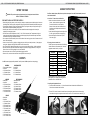
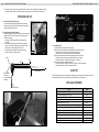
1
801000, 801005, 801010
801015, 801025
All Bearfoot Tools by Studio Pro™ are manufactured to high quality standards and are serviced by highly
qualified technicians.
Electric Mandrel Spinner (EMS) is warranted to the original purchaser for one full year from the original
purchase date. During the 12 month period, if you feel the Electric Mandrel Spinner (EMS) is not performing
properly and needs to be serviced, contact Diamond Tech at 800-937-9593 or email [email protected]
for a Return Authorization Number. Equipment will not be accepted at Diamond Tech without a Return
Authorization Number.
If returning your Electric Mandrel Spinner (EMS) for evaluation or repair, be sure to include your Name,
Address, Daytime Phone Number with Area Code and a letter explaining the specific problem you are
encountering. You will be contacted if any necessary parts or service are not covered under the warranty.
Date of purchase ___ / ___ / ___
Mark the Return Authorization Number clearly on every package! Do not send this product back
without such prior authorization! Return postage and insurance are the responsibility of the consumer.
Diamond Tech will return your Electric Mandrel Spinner (EMS) postage paid and insured if it is under
warranty. Any Electric Mandrel Spinner (EMS)no longer under warranty will be returned at the owner’s
expense. Diamond Tech reserves the right to repair or replace faulty equipment at our discretion. The
Electric Mandrel Spinner (EMS)is warranted against defective materials or workmanship. If the Electric
Mandrel Spinner (EMS)suffers damage due to customer modifications and/or is used for any application
other than that for which it was designed, this warranty is void. This warranty does not include damage
due to: (A) neglect (B) accident (C) unreasonable use (D) improper maintenance (E) any other causes
not attributed to defects in material or workmanship. Any implied or otherwise explicit guarantees made
through merchandiser of this product are not covered in this warranty coverage agreement and are
expressly disclaimed.
IMPORTANT NOTE: This tool was designed for certain applications only. Diamond Tech strongly
recommends that this tool NOT be modified and/or used for any application other than that for which it
was designed. If you have any questions relative to its application, please contact us and we will advise
as to it proper use.
Diamond Tech, USA
5600 Airport Blvd. Suite C, Tampa, Florida 33634
Tech Support: 800-937-9593 (U.S.A., Canada) | 813-806-2923 (International)
Fax: 800-299-3313 | E-mail: [email protected]
www.DiamondTechCrafts.com | www.DiamondTechGlass.com
12/2012
Electric Mandrel Spinner (EMS) OPERATIONS MANUAL - Page 2
Page 1 - Electric Mandrel Spinner (EMS) OPERATIONS MANUAL
Assembly Instructions
Before You Begin
WARNING: This product contains small parts that may be a choking hazard to small children.
KEEP OUT OF REACH OF CHILDREN.
READ AND FOLLOW ALL INSTRUCTIONS CAREFULLY
• When working with glass, protect your feet and legs by wearing non-synthetic pants and closed top shoes. Never wear
loose fitting clothes, neckties, jewelry and gloves that may get caught in the Electric Mandrel Spinner (EMS) moving parts.
• Eye protection is essential. Cold glass, when heated too quickly, may fragment. Always wear eye protective gear to
shield yourself from possible hazardous glass projectiles.
• Make sure your work area is well ventilated, free from combustible material and equipped with a handy fire extinguisher for emergency purposes.
• Glass and flame can reach temperatures of 1400° F - 1600° F which is extremely hot. Temperatures this high can
cause serious bodily harm and property damage if not handled properly. Keep torch and beads away from children
and animals while working in the flame and cooling.
• Do not expose the Electric Mandrel Spinner to wet conditions. Water entering a power tool will increase the risk of
electric shock and damage.
• Never use the cord for carrying, pulling or unplugging the power tool. Keep cord away from heat, oil, sharp edges or
moving parts. Damaged or entangled cords increase the risk of electric shock.
• Do not use the Electric Mandrel Spinner while you are tired or under the influence of drugs, alcohol or medication.
• Disconnect the battery pack from the EMS before making any adjustments, changing accessories, or storing tools.
When tool is not in use for long periods of time, remove batteries
• Be sure the power switch is in the OFF position before plugging in the EMS.
• When not in use, turn the switches and knob in the off position to save battery life.
Contents
Your EMS has been shipped partially assembled. Carefully remove the EMS and parts from their packaging.
•
•
•
•
•
ORIGINAL
Electric Mandrel Spinner
Power Box
3/32” Mandrel Sleeve
1/8” Mandrel Sleeve
5/32” Mandrel Sleeve
•
•
•
•
•
ORIGINAL PETITE
Petitie EMS
Power Box
3/32” Mandrel Sleeve
1/8” Mandrel Sleeve
5/32” Mandrel Sleeve
•
•
•
•
•
•
•
MIDSIZE
Midsize EMS
Power Box
3/32” Mandrel Sleeve
1/8” Mandrel Sleeve
5/32” Mandrel Sleeve
3/16” Mandrel Sleeve
7/32” Mandrel Sleeve
•
•
•
•
•
•
•
PETITE MIDSIZE
Petite Midsize EMS
Power Box
3/32” Mandrel Sleeve
1/8” Mandrel Sleeve
5/32” Mandrel Sleeve
3/16” Mandrel Sleeve
7/32” Mandrel Sleeve
•
•
•
•
•
•
•
•
•
•
•
DELUXE
Deluxe EMS
Power Box
3/32” Mandrel Sleeve
1/8” Mandrel Sleeve
5/32” Mandrel Sleeve
3/16” Mandrel Sleeve
7/32” Mandrel Sleeve
1/4” Mandrel Sleeve
1/32” Mandrel Sleeve
5/16” Mandrel Sleeve
11/32” Mandrel Sleeve
Your Electric Mandrel Spinner (EMS) will arrive packed as three pieces: Power Box, Electric Mandrel Spinner and
a set of Mandrel Holders.
A. Install two “D” batteries into the Power Box.
1) Make sure switches and rheostat are in the OFF
position – switches should be centered and the
rheostat dial should be in the OFF position.
Remove the four screws from the bottom of the
Power Box using a Phillips-head screwdriver and
remove cover.
2) Insert batteries following the direction indicated on
the cell, negative should face the spring (Fig. 1).
3) Return the Power Box lid and secure in place
with screws (Fig. 2).
Fig.1
B. Choosing the correct Mandrel size.
The EMS may contain any combination of the following
mandrel sleeves and one stationary axle. Choose the
appropriate mandrel size for your project:
SLEEVE SIZE
MANDREL SIZE
3/32”
1/16”
1/8”
3/32”
5/32”
1/8”
3/16”
5/32”
7/32”
3/16”
1/4”
7/32”
9/32”
1/4”
5/16”
9/32”
11/32”
5/16”
Fig.2
Mandrel Adaptors of 5/64” and 3/16” mandrel are
sold separately. 3/16” Adaptor fits the Original and
Petite EMS and 5/64” fits all EMS sizes.
C. Installing and Using Mandrel Sleeves
1) To use the smallest mandrel size, 1/16”, leave all mandrel sleeves included with the EMS inside the
axle and insert the mandrel into the sleeve.
2) To use a 5/32” mandrel, remove all mandrel sleeves by inserting the mandrel into the axel and pushing
excess sleeves through to the opposite end and remove. Insert the 5/32” mandrel into the sleeve (Fig. 3).
Fig.3
Original Mandrel Spinner
Electric Mandrel Spinner (EMS) OPERATIONS MANUAL - Page 4
Page 3 - Electric Mandrel Spinner (EMS) OPERATIONS MANUAL
3) If mandrel does not fit snugly, adjust the mandrel sleeve. To do so, remove the mandrel and compress the sides of
the mandrel sleeve with pliers, alternating around the circumference of the sleeve until you have a tight fit.
OPERATIONS AND USE
A. Connecting the EMS with the Power Box.
To connect the Electric Mandrel Spinner (EMS) to the Power Box,
simply insert plug and press firmly. Failure to properly connect may
result in opposing operations (Fig. 4).
B. Electric Mandel Spinner (EMS) Operation.
The EMS is equipped with a clutch located adjacent to the main body,
opposite motor. The clutch allows the user to temporaily stop the
mandrel from spinning.
1) To operate the EMS, both switches must be engaged on the
Power Box.
2) To manually slow down the speed of the mandrel, apply light
pressure to the clutch and release to resume standard motion.
Use this motion to slowly apply detail to the bead.
3) To temporarily stop the motion of the mandrel, apply firm
pressure on the clutch, release to resume.
Gears
C. Power Box Operation
1) To operate the EMS, both switches must be engaged.
2) The switch closest to the rheostat controls the direction of the axle and the spin.
- Position the switch to the right, and the mandrel will spin forward.
- Position the switch to the left, and the mandrel will spin backward.
3) The switch furthest from the rheostat knob controls the speed of the mandrel.
- Position the switch to the right and the mandrel will spin at a slow speed.
- Position the switch left, and the mandrel will spin at a faster speed.
4) The rheostat knob allows additional speed control.
- To increase your speed, whether set on slow or fast speed, turn the knob clockwise.
- To decrease your speed, turn the knob counter-clockwise.
Fig.4
Clutch
EMS Body
QUICK TIPS
Mandrel Sleeves
Opening allows
user to push
through unwanted
mandrels
Axel
Only feed molten glass onto the spinning mandrel, the EMS spins at a much higher rate than normal spinning – the
hotter temperature allows for better gravitational pull and easier release from the glass rod.
PARTS AND ACCESSORIES
Power Box Plug
PART
SKU
1/16” MANDREL SLEEVES FOR EMS - EACH
802125
3/32” MANDREL SLEEVES FOR EMS - EACH
802130
1/8” MANDREL SLEEVES FOR EMS - EACH
802135
ADAPTOR SLEEVES 5/64” - EACH
802145
ADAPTOR SLEEVES 3/16” - EACH
802150
Small Replacement Clutch (fits Original & Petite EMS)
802160
Medium Replacement Clutch (fits Midsize & Midsize Petite EMS)
802161
Large Replacement Clutch (fits Deluxe EMS)
802162
Sleeve Set I (3/32, 1/8, 5/32)
802137
Sleeve Set II (3/32, 732 use in conj with Set I)
802139
Sleeve Set III (1/4, 9/32, 5/16, 11/32, 3/8 use in conj with Set I&II)
802141
POWER BOX ONLY
802200