1
series
USER'S MANUAL
General Purpose Communication Module
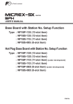
Type: NP1L-RS1 (RS-232C: 1CH, RS-485: 1CH)
NP1L-RS2 (RS-232C: 1CH)
NP1L-RS3 (RS-232C: 2CH)
NP1L-RS4 (RS-485: 1CH)
NP1L-RS5 (RS-485: 2CH)
FEH225d
Preface
This User’s Manual explains the system configuration of SPH general purpose communication module, the specifications
and operation of the modules.
Read this manual carefully to ensure correct operation. When using modules or peripheral devices, be sure to read the
corresponding user’s manuals listed below.
<Relative manuals for the SX-Programmer Expert (D300win)>
Title
Manual No.
Contents
User's Manual Instruction,
MICREX-SX series
FEH200
Explains the memory, language and system definitions of the
MICREX-SX series.
User's Manual Hardware,
MICREX-SX series SPH
FEH201
Explains the system configuration, the specifications and
operations of modules in the MICREX-SX series.
User's Manual D300win <Reference>,
MICREX-SX series
FEH254
Explains the menu and icon of D300winV2 and all of the
operations of D300winV2.
User's Manual D300win <Reference>,
MICREX-SX series
FEH257
Explains the menu and icon of D300winV3 and all of the
operations of D300winV3.
User's Manual Standard Extended FB,
MICREX-SX series
FEH255
Explains the specification of Standard Extended FB of the
attachment to D300win.
<Relative manuals for the SX-Programmer Standard (Standard Loader)>
Title
Manual No.
Contents
User's Manual Instruction,
MICREX-SX series
FEH588
Explains the memory, language and system definitions of the
MICREX-SX series.
User's Manual Hardware,
MICREX-SX series SPH
FEH201
Explains the system configuration, the specifications and
operations of modules in the MICREX-SX series.
User's Manual
SX-Programmer Standard <Reference>,
MICREX-SX series
FEH590
Explains the menu and icon of the SX-Programmer Standard
and all of the operations of the SX-Programmer Standard.
*This manual is structured to be applicable to both D300win and Standard Loader.
*In addition to the above manuals, the following Fuji Electric FA Components & Systems Co., Ltd. site offers various
manuals and technical documents associated with MICREX-SX.
URL http://www.fujielectric.co.jp/fcs/eng/index.html
Notes
1. This manual may not be reproduced in whole or part in any form without prior written approval by the
manufacturer.
2. The contents of this manual (including specifications) are subject to change without prior notice.
3. If you find any ambiguous or incorrect descriptions in this manual, please write them down (along with the manual
No.shown on the cover) and contact FUJI.
Safety Precautions
Be sure to read the “Safety Precautions” thoroughly before using the module.
Here, the safety precaution items are classified into “Warning” and “Caution.”
Warning : Incorrect handling of the device may result in death or serious injury.
Caution : Incorrect handling of the device may result in minor injury or physical damage.
Even some items indicated by “Caution” may also result in a serious accident.
Both safety instruction categories provide important information. Be sure to strictly observe these instructions.
Warning
Never touch any part of charged circuits as terminals and exposed metal portion while the power is turned ON.
It may result in an electric shock to theoperator.
Turn OFF the power before mounting, dismounting, wiring, maintaining or checking, otherwise, electric shock, erratic
operation or troubles might occur.
Place the emergency stop circuit, interlock circuit or the like for safety outside the PLC.
A failure of PLC might break or cause problems to the machine.
Do not connect in reverse polarity, charge (except rechargeable ones), disassemble, heat, throw in fire or short-circuit
the batteries, otherwise, they might burst or take fire.
If batteries have any deformation, spilled fluids, or other abnormality, do not use them. The use of such batteries might
cause explosion or firing.
Do not open the FG terminal with the LG-FG short circuited.
(It must be grounded, otherwise it might cause electric shock.)
Safety Precautions
Caution
Do not use one found damaged or deformed when unpacked, otherwise, failure or erratic operation might be caused.
Do not shock the product by dropping or tipping it over, otherwise, it might be damaged or troubled.
Follow the directions of the operating instructions when mounting the product.
If mounting is improper, the product might drop or develop problems or erratic operations.
Use the rated voltage and current mentioned in the operating instructions and manual. Use beyond the rated values
might cause fire, erratic operation or failure.
Operate (keep) in the environment specified in the operating instructions and manual. High temperature, high humidity,
condensation, dust, corrosive gases, oil, organic solvents, excessive vibration or shock might cause electric shock, fire,
erratic operation or failure.
Select a wire size to suit the applied voltage and carrying current. Tighten the wire terminals to the specified torque.
Inappropriate wiring or tightening might cause fire, malfunction, failure, or might cause the product to drop from its
mounting.
Contaminants, wiring chips, iron powder or other foreign matter must not enter the device when installing it, otherwise,
erratic operation or failure might occur.
Remove the dust-cover seals of modules after wiring, fire, accidents, failue or fault might occur.
Connect the ground terminal to the ground, otherwise, an erratic operation might occur.
Periodically make sure the terminal screws and mounting screws are securely tightened.
Operation at a loosened status might cause fire or erratic operation.
Put the furnished connector covers on unused connectors, otherwise, failure or erratic operation might occur.
Install the furnished terminal cover on the terminal block, otherwise, electric shock or fire might occur.
Sufficiently make sure of safety before program change, forced output, starting, stopping or anything else during a run.
The wrong operation might break or cause machine problems.
Engage the loader connector in a correct orientation, otherwise, an erratic operation might occur.
Before touching the PLC, discharge any static electricity that may have been collected on your body.
To discharge it, touch a grounded metallic object. Static electricity might cause erratic operation or failure of the module.
Be sure to install the electrical wiring correctly and securely, observing the operating instructions and manual. Wrong or
loose wiring might cause fire, accidents, or failure.
When disengaging the plug from the outlet, do not pull the cord, otherwiase, break of cable might cause fire or failure.
Do not attempt to change system configurations (such as installing or removing I/O modules) while the power is ON,
otherwise, failure or erratic operation might occur.
Do not attemp to repair the module by yourself contact your Fuji Electric agent. When replacing the batteries, correctly
and securely connect the battery connectors, otherwise, fire, accidents or failure might occure.
To clean the module, turn power off and wipe the module with a cloth moistened with warm water. Do not use thinner or
other organic solvents, as the module surface might become deformed or discolored.
Do not remodel or disassemble the product, otherwise, a failure might occur.
Follow the regulations of industrial wastes when the device is to be discarded.
The modules covered in these operating instructions have not been designed or manufactured for use in equipment or
systems which, in the event of failure, can lead to loss of human life.
If you intend to use the modules covered in these operating instructions for special applications, such as for nuclear
energy control, aerospace, medical, or transportation, please consult your Fuji Electric agent.
Be sure to provide protective measures when using the module covered in these operating instructions in equipment
which, in the event of failure, may lead to loss of human life or other grave results.
External power supply (such as 24V DC power supply) which is connected to DC I/O should be strongly isolated from
AC power supply.
Revisions
*Manual No. is shown on the cover.
Printed on
*Manual No.
Revision contents
Sep. 1998
FEH225
First edition
Jan. 2002
FEH225a
Contents changed according to changes of extended FB specifications.
• Contents changed according to inclusion of a part of the non-procedural
FB in the firmware and reduction of the capacity of the non-procedural FB.
• Contents changed according to addition of the modem loader function.
• Descriptions of the standard extended FB in Appendix 2 deleted and
reprinted in "Standard Extended FBs for General Purpose Communication Module
(FEH255)."
Mar. 2004
FEH225b
• The content of "6-2 Wiring method" was reviewed.
• Wrong description in paragraph 3-2-7 was corrected.
• Communication specifications for "Modem loader" and "Programming loader"
modes were added to paragraph 2-3-2.
Jan. 2005
FEH225c
•
•
•
•
•
Jul. 2006
FEH225d
• NP1L-RS5 was added (Appendix 4)
NP1L-RS3 was added
Wrong description in paragraph 3-4-1 was corrected.
Paragraph 4-3-1 Note2 was added.
Wrong description in paragraph 6-2-2 was corrected.
Appendix 2-3-1 Memory type code 00h, 01h deleted.
Contents
Preface
Safety Precautions
Revisions
Contents
Page
Section 1 General ..........................................................................................1-1
1-1
1-2
1-3
1-4
General ............................................................................................................................................
Selections and Programs for the Communication .....................................................................
General Purpose Communication Package for Factory Automation Machine ........................
Product Versions and Supported Functions ...............................................................................
1-1
1-2
1-3
1-4
1-4-1 Supported functions .............................................................................................................................. 1-4
1-4-2 Available standard extended FB ........................................................................................................... 1-4
Section 2 Specifications ...............................................................................2-1
2-1 General Specifications .................................................................................................................. 2-1
2-2 Communication Specifications ..................................................................................................... 2-2
2-3 Names and Functions .................................................................................................................... 2-3
2-3-1 Names ................................................................................................................................................... 2-3
2-3-2 Functions ............................................................................................................................................... 2-4
2-4 Dimensions ..................................................................................................................................... 2-7
Section 3 System Configuration ..................................................................3-1
3-1 Mounting Restrictions ................................................................................................................... 3-1
3-1-1 Mounting position ................................................................................................................................. 3-1
3-1-2 Number of mountable modules ............................................................................................................ 3-1
3-2 System Configurations .................................................................................................................. 3-2
3-2-1 1:1 Connection using RS-232C port ..................................................................................................... 3-2
3-2-2 1:N Connection using RS-485 port (N = max. 31 modules) ................................................................. 3-3
3-2-3 Connecting independently to RS-232C and RS-485 ports ................................................................... 3-4
3-2-4 Connection using RS-232C and RS-485 ports (2) ............................................................................... 3-5
3-2-5 Connecting a personal computer loader to the RS-232C port and RS-485 port ................................. 3-7
3-2-6 Loader network configuration using RS-485 ........................................................................................ 3-7
3-2-7 Loader network configuration using modems (1) ................................................................................. 3-8
3-3 Loader Connecting Cable .............................................................................................................. 3-9
3-3-1 When connecting to RS-232C port ....................................................................................................... 3-9
3-3-2 When connecting to RS-485 port .......................................................................................................... 3-9
3-4 Self-diagnosis ............................................................................................................................... 3-10
3-4-1 Self-diagnosis mode 1 ........................................................................................................................ 3-10
3-4-2 Self-diagnosis mode 2 ........................................................................................................................ 3-11
Section 4 Software Interface ........................................................................4-1
4-1 General ............................................................................................................................................ 4-1
4-2 Specifications for Non-procedural FB ......................................................................................... 4-3
4-2-1 Communication specification ................................................................................................................ 4-3
4-2-2 FB format ............................................................................................................................................... 4-4
4-2-3 FB terminals .......................................................................................................................................... 4-5
Contents
Page
4-3 Initialization ..................................................................................................................................... 4-7
4-3-1 Initialization parameters ........................................................................................................................ 4-7
4-3-2 Initialization procedure ........................................................................................................................ 4-10
4-3-3 OPEN status list .................................................................................................................................. 4-10
4-4 Data Sending ................................................................................................................................ 4-11
4-4-1 Data sending procedure ...................................................................................................................... 4-11
4-4-2 Send status list .................................................................................................................................... 4-12
4-5 Data Receiving .............................................................................................................................. 4-13
4-5-1 Data receiving procedure .................................................................................................................... 4-13
4-5-2 Receiving status list ............................................................................................................................ 4-14
4-6 RAS Information ........................................................................................................................... 4-15
Section 5 Programming ................................................................................5-1
5-1
5-2
5-3
5-4
5-5
5-6
5-7
Communication Program ..............................................................................................................
Installation Procedure of Standard Extended FB .......................................................................
Registration in Library ...................................................................................................................
Pasting Non-procedural FB ...........................................................................................................
Communication Parameters Setting ............................................................................................
Writing the Send Data ....................................................................................................................
Connecting Variables and Commands to FB Terminals .............................................................
5-1
5-2
5-5
5-6
5-7
5-8
5-9
5-7-1 Connecting variable to “PARA” terminal ................................................................................................ 5-9
5-7-2 Operation for starting FB ....................................................................................................................... 5-9
5-7-3 Operation for sending data .................................................................................................................. 5-10
5-7-4 Data receiving operation ..................................................................................................................... 5-10
Section 6 Wiring.............................................................................................6-1
6-1 Precautions ..................................................................................................................................... 6-1
6-2 Wiring Method ................................................................................................................................. 6-2
6-2-1 When RS-485 is used (2-wire) .............................................................................................................. 6-2
6-2-2 When RS-485 is used (4-wire system) ................................................................................................. 6-2
6-2-3 When RS-232C is used ......................................................................................................................... 6-3
Section 7 RAS ................................................................................................7-1
7-1 RAS Information of General Purpose Communication Module ................................................ 7-1
Appendix 1 JIS Code .............................................................................App.1-1
JIS 7-bit Codes ........................................................................................................................... App.1-1
JIS 8-bit Codes ........................................................................................................................... App.1-1
Appendix 2 Data Access by Command ............................................... App.2-1
Appendix 2-1 Command Overview ............................................................................................. App.2-1
Appendix 2-2 Send Data Format of Commands ........................................................................ App.2-2
Appendix 2-3 Loader Command Details .................................................................................... App.2-4
Appendix 2-3-1 Read data ....................................................................................................................... App.2-4
Appendix 2-3-2 Write data ....................................................................................................................... App.2-6
Appendix 2-3-3 Batch Start of CPUs ....................................................................................................... App.2-7
Appendix 2-3-4 Batch Initialization Start of CPUs .................................................................................. App.2-7
Appendix 2-3-5 Batch Stop of CPUs ....................................................................................................... App.2-7
Appendix 2-3-6 Batch Reset of CPUs ..................................................................................................... App.2-8
Contents
Page
Appendix 2-3-7 Individual Start of CPU .................................................................................................. App.2-8
Appendix 2-3-8 Individual Initialization Start of CPU .............................................................................. App.2-8
Appendix 2-3-9 Individual Stop of CPU ................................................................................................... App.2-9
Appendix 2-3-10 Individual Reset of CPU ............................................................................................... App.2-9
Appendix 3 Additional Explanation for NP1L-RS3 ............................. App.3-1
Appendix 3-1 Applicable Version for NP1L-RS3 ........................................................................ App.3-1
Appendix 3-2 General Specifications ......................................................................................... App.3-1
Appendix 3-3 Names and Functions .......................................................................................... App.3-1
Appendix 3-3-1 Names ............................................................................................................................ App.3-1
Appendix 3-3-2 Functions ........................................................................................................................ App.3-2
Appendix 3-4 Self-diagnosis ....................................................................................................... App.3-3
Appendix 3-4-1 Self-diagnosis mode 1 .................................................................................................. App.3-3
Appendix 3-4-2 Self-diagnosis mode 2 ................................................................................................... App.3-3
Appendix 3-5 Initialization Parameters ...................................................................................... App.3-3
Appendix 3-6 Detailed RAS ......................................................................................................... App.3-4
Appendix 4 Additional Explanation for NP1L-RS5 ............................. App.4-1
Appendix 4-1 Applicable Version for NP1L-RS5 ........................................................................ App.4-1
Appendix 4-2 General Specifications ......................................................................................... App.4-1
Appendix 4-3 Names and Functions .......................................................................................... App.4-1
Appendix 4-3-1 Names ............................................................................................................................ App.4-1
Appendix 4-3-2 Functions ........................................................................................................................ App.4-2
Appendix 4-4 Self-diagnosis ....................................................................................................... App.4-4
Appendix 4-4-1 Self-diagnosis mode 1 .................................................................................................. App.4-4
Appendix 4-4-2 Self-diagnosis mode 2 ................................................................................................... App.4-4
Appendix 4-5 Initialization Parameters ...................................................................................... App.4-4
Appendix 4-6 Loader Network Functions .................................................................................. App.4-4
Appendix 4-7 Detailed RAS ......................................................................................................... App.4-5
Section 1 General
Page
1-1 General ......................................................................................................................... 1-1
1-2 Selections and Programs for the Communication ................................................... 1-2
1-3 General Purpose Communication Package for Factory Automation Machine ...... 1-3
1-4 Product Versions and Supported Functions ............................................................ 1-4
1-4-1 Supported functions .............................................................................................................. 1-4
1-4-2 Available standard extended FB ........................................................................................... 1-4
Section 1 General
General
1-1 General
NP1L-RS1/2/4 are communication modules which enable data communication between a CPU module and external
devices, and which are connected to the base board (on the SX bus) of MICREX-SX series. (NP1L-RS1/2/4 are
sometimes abbreviated as RS1/2/4.)
The port type and the number of ports are as follows:
Type
No. of ports
NP1L-RS1
RS-232C: 1 channel, RS-485: 1 channel
NP1L-RS2
RS-232C: 1 channel
NP1L-RS4
RS-485: 1 channel
RS1
RS-232C
(1:1)
Power
supply
CPU
I/O
I/O
I/O
External
device
I/O
RS-485
(1:n) n = Max. 31
External
device
External
device
External
device
As an external device,
it is possible to connect
a loader software
package for in a
personal computer.
Loader software package for a personal computer
<Overview of SX bus connection>
Total length of SX bus: Max. 25m
I/O
I/O
I/O
I/O
General purpose
communication module
CPU
Data transmission between CPU and an
external device is performed via the SX bus.
External device
1-1
1-2 Selections and Programs for the Communication
The following preparations are necessary for RS1/2/4 to communicate between a CPU module of MICREX-SX series and
external devices.
MICREX-SX series
RS1/2/4
Power
supply
CPU
I/O
I/O
I/O
I/O
<CPU modules side>
<RS1/2/4 side>
Initializing parameters for a RS-232C port and a
RS-485 port.
(Transmission speed, data length, parity bit, stop
bits etc.,)
Application software for the communication.
Selection switch of the module is used.
RS-485 station No. selection switch (0 to F)
If RS-485 port is not used, the selection is not
necessary.
Mode selection switch
Device selection of RS-232C port and RS-485
port, Data conversion
FA packages are optionally provided
for each external device.
RS-485 terminating resistor ON/OFF switch
ON/OFF of terminating resistor is selected.
If RS-485 port is not used, this switch is ignored.
External device
<External device side>
Transmission speed, data length, parity bit, stop bits etc.
Application software for the communication.
1-2
1-3 General Purpose Communication Package
for Factory Automation Machine
Nonsequenced FB is provided for NP1L-RS1/2/4 to communicate with external serial devices. (Included in D300win.)
General purpose communication package for Factory Automation machine (NP4N-COMF) is provided to communicate
with specified external serial devices.
NP4N-COMF includes following function blocks.
Procedure
Temperature
controller
ID system
Bar code reader
SECS
FB name
Device
_CrkREX
RIKA KOGYOU CO., LTD. REX-F, REX-D, FAREX-SR series
_Com AX
OMRON Corporation. Digital temperature controller E5AX, E5XJ series
_ComCK
OMRON Corporation. Digital temperature controller E5CK series
_CymSDC
Yamatake Corporation. Digitronic temperature controller SDC40A/40G series
_ComV6
OMRON Corporation. V600 series
_CshDS
SHARP MANUFACTURING SYSTEM CORPORATION. Microwave ID plate
system DS series
_CymWAM
Yamatake Corporation. Code distinguish ID system WAM120 series
_CizFP
IDEC IZUMI CORPORATION. Data carrier system FP1A series
_CtkTCD
THOKEN Co., Ltd. TCD8200/8500, TLMS-3200RV series
_CndBCC
NIPPON ELECTRIC INDUSTRY CO., LTD. BCC2600 series, BL500, BL700
_CkyBL
KEYENCE CORPORATION. BL180 series
_CizDS
IZUMI DATA LOGIC CO., LTD. Bar code reader DS series
_C_SECS
SECS procedure semiconductor manufacturing system (for SECS-I only)
Note: General purpose communication FB in the table below is included in D300win.
Type
FB name
FB Overview
_C_free
(Note 1) Non-procedural FB
Send: 512 words Receive: 512 words
_Cfr252
(Note 1) Non-procedural FB
Send: 252 words Receive: 252 words
_Cfr128
(Note 1) Non-procedural FB
Send: 128 words Receive: 128 words
_Cfr64
(Note 1) Non-procedural FB
Send: 64 words Receive: 64 words
_Cfr32
(Note 1) Non-procedural FB
Send: 32 words Receive: 32 words
_Cfrpr
Non-procedure FB which built into communication protocol
Send: 512 words Receive: 512 words
(Note 1)
The program capacity is reduced by performing a part of the communication
processing with the module.
_Cfrp2
Non-procedure FB which built into communication protocol
Send: 512 words Receive: 512 words
(Note 2) The program capacity is reduced by performing a part of the communication
processing with the module.In addition, communication processing can be
mabe high-speed by using two SX bus message ports.
_CfdFRN
(Note 2) For FUJI Inverter FRENIC series
_CfdFVR
(Note 2) For FUJI Inverter FVR-C11 series (FGI-BUS)
_Cfvrpr
For FUJI Inverter FVR-C11 series (FGI-BUS)
(Note 2) The program capacity is reduced by performing a part of the communication
processing with the module.
For FUJI heater
_CfdPYX
(Note 2) For FUJI heater PYX series and PYH series
For FUJI bar code
_CfdPK
(Note 2) For FUJI bar code reader PK2 series
Non-procedural FB
For FUJI Inverter
Note 1: Refer to Section 4 in this manual.
Note 2: For _Cfrp2, _CfdFRN, _CfdFVR, _Cfvrpr, _CfdPYX, and _CfdPK, refer to “MICREX-SX USER'S MANUAL
STANDARD EXTENDED FB (FEH255).”
1-3
1-4 Product Versions and Supported Functions
For the general purpose communication module, supported functions and available FBs depend on the product version.
1-4-1 Supported functions
Note 2:
Format and version
Modem-based loader function 1
: supported
: Not supported
Modem-based loader function 2
Earlier than NP1L-RS1 V.1031
x
x
Earlier than NP1L-RS2 V.1031
x
x
Earlier than NP1L-RS4 V.1031
—Note 1
—Note 1
NP1L-RS1 V.1031 or later
o
x
NP1L-RS2 V.1031 or later
o
x
NP1L-RS4 V.1031 or later
—Note 1
—Note 1
NP1L-RS1 V.2535 or later
o
o
NP1L-RS2 V.2535 or later
o
o
NP1L-RS4 V.2535 or later
—Note 1
—Note 1
Note 1: The modem-based loader functions are functions which realize remote operation and programming by connecting
a modem to the RS-232C port and using the public circuit. These functions cannot be used with the NP1L-RS4
which is provided only with the RS-485 port.
Note 2: With modem-based function 1, the transmission rate between this module and a commercial modem is fixed to
19200 bps. With modem-based function 2, the transmission rate can be selected from 9600, 19200, and 38400
bps.
1-4-2 Available standard extended FB
Applicable version of general
purpose communication
module
FB Name FB Overview
_C_free
Non-procedural FB
Send: 512 words Receive: 512 words
_Cfr252
Non-procedural FB
Send: 252 words Receive: 252 words
_Cfr128
Non-procedural FB
Send: 128 words Receive: 128 words
_Cfr64
Non-procedural FB
Send: 64 words Receive: 64 words
_Cfr32
Non-procedural FB
Send: 32 words Receive: 32 words
_Cfrpr
Non-procedure FB which built into communication protocol
Send: 512 words Receive: 512 words
The program capacity is reduced by performing a part of the communication V.2535 or later
processing with the module.
_CfRP2
Non-procedure FB which built into communication protocol
Send: 512 words Receive: 512 words
The program capacity is reduced by performing a part of the communication
V.2536 or later
processing with the module.In addition,communication processing can be
mabe high-speed by using two SX bus message ports.
_CfdFRN
For FUJI Inverter FRENIC series
All versions Note 1
_CfdFVR
For FUJI Inverter FVR-C11 series (FGI-BUS)
All versions Note 1
_Cfvrpr
For FUJI Inverter FVR-C11 series (FGI-BUS)
The program capacity is reduced by performing a part of the communication V.2536 or later
processing with the module.
_CfdPYX
For FUJI heater PYX series and PYH series
All versions Note 1
_CfdPK
For FUJI bar code reader PK2 series
All versions Note 2
All versions
Note 1
Note 1: This FB uses the RS-485 port. Cannot be used with the NP1L-RS2 which is provided only with the RS-232C port.
Note 2: This FB uses the RS-232C port. Cannot be used with the NP1L-RS4 which is provided only with the RS-485 port.
1-4
Section 2 Specifications
Page
2-1 General Specifications ............................................................................................... 2-1
2-2 Communication Specifications ................................................................................. 2-2
2-3 Names and Functions ................................................................................................. 2-3
2-3-1 Names ................................................................................................................................... 2-3
(1) NP1L-RS1 ............................................................................................................................................... 2-3
(2) NP1L-RS2 ............................................................................................................................................... 2-3
(3) NP1L-RS4 ............................................................................................................................................... 2-4
2-3-2 Functions .............................................................................................................................. 2-4
2-4 Dimensions .................................................................................................................. 2-7
General specifications
Section 2 Specifications
2-1 General Specifications
Item
Physical
environmental
conditions
Specification
Operating ambient
temperature
0 to 55° C
Storage
temperature
-25 to +70° C
Relative humidity
20 to 95%RH no condensation
Pollution degree
2
Corrosion immunity Free from corrosive gases. Not stained with organic solvents.
Mechanical
service
conditions
Electrical
service
conditions
Operating altitude
2000m or less above sea level (Transport condition: 70kPa or more)
Vibration
Half amplitude: 0.15mm, Constant acceleration: 19.6m/s2
Shock
Acceleration peak: 147m/s2
Noise immunity
1.5kV (1kV: clamping to transmission line) , rise time 1ns, pulse width 1µs (noise
simulator)
Electrostatic
discharge
Contact discharge: ±6kV
Aerial discharge: ±8kV
Radioelectromagn10V/m (80MHz to 1000MHz)
etic field
Construction
Panel-mounted type
Cooling
Air cooling
Isolation method
Photocoupler
Dielectric strength
445V AC 1 minute (between I/O connector pins and ground)
Insulation resistance
10MΩ or more with 500V DC megger (between I/O connector pins and ground)
Internal current consumption
NP1L-RS1: 24V DC, 110mA or less
NP1L-RS2: 24V DC, 90mA or less
NP1L-RS4: 24V DC, 80mA or less
Mass
NP1L-RS1: Approx. 170g
NP1L-RS2: Approx. 160g
NP1L-RS4: Approx. 160g
Dimensions
Described in 2-4
2-1
Communication specifications
2-2 Communication Specifications
Item
Specification
RS-232C
RS-485
NP1L-RS1, NP1L-RS2, NP1L-RS4
Type
External interface
Port
NP1L-RS1
1 channel
1 channel
NP1L-RS2
1 channel
—
NP1L-RS4
—
1 channel
Communication method half-duplex communication
Synchronization
method
(Note 1)
Start-stop synchronous transmission
Transmission speed
1200/2400/4800/9600/19200/38400/57600 bps
(Note 2)
(for RS1, max. 57600bps or less in total of 2 channels)
(Note 3)
Transmission distance
15m or less
1km or less (transmission speed: 19.2kbps or less)
No. of connectable
modules
1:1 (One external device)
1:31 (Max.)
Connection method
D-sub, 9-pin connector (female)
D-sub, 9-pin connector (male)
Transmission protocol
Depends on the application program (FB) in the CPU module.
Non-procedural FB (Included in D300win)
Occupied slot
1 slot
ONL: Normally running — Green
ERR: General purpose communication module — Red
Status indication LED
ALM: Communication error — Red
RXD: Signal receiving — Green
TXD: Signal sending — Green
ALM: Communication error — Red
RXD: Signal receiving — Green
TXD: Signal sending — Green
TS1, TS2: Self-diagnosis — Green
Note 1: The use of the non-procedural FB allows this mode to be used like the full-duplex mode on applications.
Note 2: Transmission rates 300, 600, 76800, and 115200 bps can be used in the following combinations:
Version of general purpose
communication module
Standard extended FB
V.2535 or later
_Cfrpr (Non-procedural FB with built-in protocol)
V.2536 or later
_Cfrp2 (Non-procedural FB with built-in protocol, 2-message version)
_Cfvrpr (Inverter procedure FB with built-in protocol)
Note 3: This limitation is applied to RS1 before version V2535.
2-2
Names and functions
2-3 Names and Functions
2-3-1 Names
(1) NP1L-RS1
1) Status indication LED
2) Mode selection switch
ALM
ERR
TS2
78
B c DE
F 0 12
789A
MODE
RS485
No.
(0-F)
TS1
9 01
4) RS-232C port
(D-sub, 9-pin, female)
RS232
RXD TXD
RS485
456
ONL
23
3 456
3) RS-485 station No. selection switch
Nameplate
5) RS-485 terminating resistor
ON-OFF switch
RS232C
6) RS-485 port
(D-sub, 9-pin, male)
RS485
TERM. 1-2-3
RS485
(2) NP1L-RS2
1) Status indication LED
2) Mode selection switch
ONL
ALM
RS232
RXD TXD
TS2
78
9 01
23
MODE
456
ERR
4) RS-232C port
(D-sub, 9-pin, female)
TS1
Nameplate
RS232C
2-3
Names and functions
2-3 Names and Functions
(3) NP1L-RS4
1) Status indication LED
2) Mode selection switch
3) RS-485 station No. selection switch
ONL
TS1
789A
B c DE
F 0 12
3 456
RS485
No.
(0-F)
TS2
78
9 01
MODE
456
RXD TXD
RS485
23
ALM
ERR
Nameplate
5) RS-485 terminating resistor ON-OFF switch
6) RS-485 port
(D-sub, 9-pin, male)
RS485
TERM. 1-2-3
RS485
2-3-2 Functions
1) Status indication LED
This LED indicates the running status of NP1L-RS1/2/4.
NP1L-RS1
ONL
ALM
ERR
RS232
RXD TXD
RS485
ALM
Green Turns on when the module is ready to communicate with the SX bus.
ERR
Red
ONL
RXD TXD
RS485
Turns on when the module is abnormal.
Turns on when the communication data via RS-232C is abnormal.
TS1
RS232C RXD Green Turns on when the RS-232C port is receiving data.
TS2
RS232C TXD Green Turns on when data is being sent from the RS-232C port.
RS485 ALM
Red
TS1
RS485 RXD
Green Turns on when the RS-485 port is receiving data.
TS2
RS485 TXD
Green Turns on when data is being sent from the RS-485 port.
TS1
Blinks when internal RAM error is detected in self-diagnosis mode 7.
Green Blinks when RS-232C turning back test is abnormal in self-diagnosis
mode 8. (RST-CTS turning-back error)
TS2
Green
NP1L-RS4
ERR
ONL
RS232C ALM Red
RS232
RXD TXD
ERR
ALM
Color Description
TS2
NP1L-RS2
ONL
Symbol
TS1
Turns on when the communication data via RS-485 is abnormal.
Blinks when RS-232C turning back test is abnormal in self-diagnosis
mode 8. (DTR-DSR turning-back error)
* Example of LED status by module status
ONL
ERR
ALM
Fatal fault of module
OFF
ON
—
Nonfatal fault of module
ON
ON
—
Data error
ON
OFF
ON
2-4
Functions
2-3 Names and Functions
B CD E
F 0 12
MODE
789A
2) Mode selection switch
This switch is used to select a connectable device, the signal conversion and the self-diagnosis for the RS-232C port and
the RS-485 port.
Switch
No.
Mode
RS-232C port
RS-485 port
RS-232C <=> RS-485 Remarks
Signal conversion
0
General purpose device General purpose device Not available
1
Programming loader
2
General purpose device Programming loader
Not available
3
Programming loader
Not available
General purpose device Not available
Programming loader
4
General purpose device General purpose device Available
5
Not used
6
Modem-loder
19200 bps
7
Self-diagnosis mode 1 (diagnoses internal memory and LED)
8
Self-diagnosis mode 2 (diagnoses RS-232C, RS-485 turning back)
9
Modem-loder
19200 bps
Programming loader
A
Modem-loder
9600 bps
General purpose device Not available
B
Modem-loder
9600 bps
Programming loader
C
Modem-loder
38400 bps
General purpose device Not available
D
Modem-loder
38400 bps
Programming loader
E
Modem-loder
76800 bps
General purpose device Not available
3 456
(Note 5) Modem-loder
F
115200 bps
General purpose device Not available
Modem-loder
115200 bps
Not available
Not available
Applies to
V2535 or later.
Applies to
V1031 or later.
Applies to
V1031 or later.
Applies to
V2535 or later.
Not available
—
Applies to
V2536 or later.
Note 1: For details of the function mode, refer to “3-2 System configuration.”
Note 2: For the self-diagnosis, refer to “3-4 Self-diagnosis.”
Note 3: “Programming loader” is the mode for connecting to D300win. Communication specifications are fixed to” 38400
bps” for transmission speed, “8 bits” for data length, “1 bit” for stop bits, and “even” for parity.
Note 4: “Modem-loader" is the mode that is basically used to connect to D300win loader via a modem. In general, for
modems, “none” is specified for parity. Therefore, in this mode, communication specifications become “8 bits” for
data length, “1 bit” for stop bits, and “none” for parity.
Note 5: Either channel is selected and used.
B CD E
F 0 12
3 456
RS485
No.
(0-F)
789A
3) RS-485 station No. selection switch
This switch used to select a RS-485 station number of NP1L-RS1 or NP1L-RS4. Selecting range is 0 to F.
2-5
Functions
2-3 Names and Functions
4) RS-232C port
This port is D-sub, 9-pin connector (female). This connector is connected to D-sub, 9-pin connector (male).
Pin
No.
1
6
9
5
M2.6
Screw
Signal name Signal direction RS1/2 to external device Description
1
CD
<==
Carrier detect
2
RD
<==
Receive data
3
SD
==>
Send data
4
ER
==>
Data terminal ready
5
SG
Signal ground (common return)
6
DR
<==
Data set ready
7
RS
==>
Request to send
8
CS
<==
Clear to send
9
RI
<==
Call indication
5) RS-485 terminating resistor ON/OFF switch
This switch used to select the ON/OFF of the RS-485 terminating resistor. There are three positions for this switch.
Switch position
Left
Center
Right
Status
2-wire type, Terminating resistor is available.
Terminating resistor is not available.
4-wire type, Terminating resistor is available.
6) RS-485 port
This port is D-sub, 9-pin connector (male). This connector is connected to D-sub, 9-pin connector (female).
Pin
No.
5
9
6
1
Signal name Signal direction RS1/4 to External device Description
1
SDB
==>
Send data signal line (-)
2
SDA
==>
Send data signal line (+)
3
(SDB)
==>
(Send data signal line (-))
4
(SDA)
==>
(Send data signal line (+))
5
SG
Signal ground (common return)
6
FG
Frame ground
7
M2.6
Screw
8
RDB
<==
Receive data signal line B (-)
9
RDA
<==
Receive data signal line A (+)
Note: For wiring, refer to “6-2 Wiring.”
2-6
Dimensions
2-4 Dimensions
Dimensions are same for NP1L-RS1,NP1L-RS2 and NP1L-RS4.
35
(37)
105
(Note)
(90)
Note: Front formation depends on each type.
2-7
90
Section 3 System Configuration
Page
3-1 Mounting Restrictions ................................................................................................ 3-1
3-1-1 Mounting position .................................................................................................................. 3-1
3-1-2 Number of mountable modules ............................................................................................. 3-1
3-2 System Configurations ............................................................................................... 3-2
3-2-1 1:1 Connection using RS-232C port ..................................................................................... 3-2
3-2-2 1:N Connection using RS-485 port (N = max. 31 modules) .................................................. 3-3
3-2-3 Connecting independently to RS-232C and RS-485 ports ................................................... 3-4
3-2-4 Connection using RS-232C and RS-485 ports (2) ................................................................ 3-5
3-2-5 Connecting a personal computer loader to the RS-232C port and RS-485 port .................. 3-7
3-2-6 Loader network configuration using RS-485 ......................................................................... 3-7
3-2-7 Loader network configuration using modems (1) .................................................................. 3-8
3-3 Loader Connecting Cable .......................................................................................... 3-9
3-3-1 When connecting to RS-232C port ....................................................................................... 3-9
3-3-2 When connecting to RS-485 port .......................................................................................... 3-9
3-4 Self-diagnosis ........................................................................................................... 3-10
3-4-1 Self-diagnosis mode 1 ........................................................................................................ 3-10
3-4-2 Self-diagnosis mode 2 ........................................................................................................ 3-11
(1) RS to CS signal check .......................................................................................................................... 3-11
(2) ER to DR signal check .......................................................................................................................... 3-11
(3) RS-232C/RS-485 data check ................................................................................................................ 3-11
(4) Preservation of the result of the check .................................................................................................. 3-11
Mounting restrictions
Section 3 System Configuration
3-1 Mounting Restrictions
3-1-1 Mounting position
NP1L-RS1/2/4 is a general purpose communication module which is connected to the SX bus of MICREX-SX series. The
mounting position on the base board is restricted as follows:
They can be mounted in any slot except those for the power supply module (the two slots from the left on the base board).
<Base board other than 6-slots base board>
Mountable slots
<6-slots base board>
Mountable slots
T-link interface module
Note: The general purpose communication modules cannot be mounted on T-link or OPCN-1 slave station base boards.
I/O
Power
supply
I/O
I/O
I/O
CPU
Power
supply
T-link master module
3-1-2 Number of mountable modules
A maximum of 16 modules per configuration can be connected. However, when other communication related modules are
used in the same configuration, the maximum number of 16 is the total of these and NP1L-RS1/2/4 modules.
P-link module (NP1L-PL1)
PE-link module (NP1L-PE1)
FL-net (OPCN-2) module (NP1L-FL1)
General purpose communication module (NP1L-RS1/2/4)
Maximum of 16 modules per configuration.
PC card interface module (NP1F-PC2)
Memory card interface module (NP1F-MM1)
3-1
1: 1 connection
3-2 System Configurations
3-2-1 1:1 Connection using RS-232C port
This configuration connects to an external device having an RS-232C interface via the RS-232C port.
The mode selection switch is set to “0” (zero).
RS1 or RS4
Power
supply
<Mode selection switch: “0”>
RS-232C port
General purpose device
RS-485 port
General purpose device
Signal conversion None
CPU
RS-232C
External device
* With RS1, a D300win personal computer loader can be connected to an RS-485 port which is not used.
In this case, the mode selection switch needs to be set to “2.”
RS1
<Mode selection switch: “2”>
Power
supply
CPU
RS-232C port
General purpose device
RS-485 port
Loader
Signal conversion
None
RS-232C
RS-485
External device
For the connection, refer to “3-3-2 When
connecting to RS-485 port.”
3-2
1: N connection
3-2 System Configurations
3-2-2 1:N Connection using RS-485 port (N = max. 31 modules)
This configuration connects to external devices having an RS-485 interface via the RS-485 port. The mode selection
switch is set to “0.” A maximum of 31 external devices can be connected. However, when all external devices are RS1 or
RS4, the maximum number is limited to 15 because only 0 to F are available for addressing.
RS1 or RS4
<Mode selection switch: “0”>
Power
supply
CPU
RS-232C port
General purpose device
RS-485 port
General purpose device
Signal conversion
None
RS-485
External device
External device
External device
A
B
C
Note: External devices A , B and C must be the same in type as well
as communication protocol. For example, this connection is not
available when A and B are temperature controllers and C is a
bar code reader.
* With NP1L-RS1, a D300win personal computer loader can be connected to an RS-232C port which is not in use.
In this case, the mode selection switch needs to be set to “1.”
RS1
<Mode selection switch: “1”>
Power
supply
CPU
RS-232C
RS-232C port
Loader
RS-485 port
General purpose device
Signal conversion
None
RS-485
External device
External device
External device
A
B
C
For the connection, refer to “3-3-1 When
connecting to RS-232C port.”
3-3
1: 1 / 1: N connection
3-2 System Configurations
3-2-3 Connecting independently to RS-232C and RS-485 ports
This configuration connects to external devices using the RS-232C port and RS-485 port. In this case, communication
through these ports is performed independently.
RS1
Power
supply
<Mode selection switch: “0”>
RS-232C port
General purpose device
RS-485 port
General purpose device
Signal conversion
None
CPU
RS-485
External device
External device
External device
A
B
C
Note: External devices A , B and C must be the same in type as well
as communication protocol. For example, this connection is not
available when A and B are temperature controllers and C is a
bar code reader.
RS-232C
External device
3-4
1: 1 / 1: N connection
3-2 System Configurations
3-2-4 Connection using RS-232C and RS-485 ports (2)
This configuration connects to external devices using the RS-232C port and RS-485 port.
RS1
<Mode selection switch: “0”>
Power
supply
RS-232C port
General purpose device
RS-485 port
General purpose device
Signal conversion Yes
CPU
RS-485
External device
External device
External device
B
C
D
RS-232C
External device A
(personal computer, etc.)
With this configuration, the following communications can be performed :
1) Communication between external device A and external device B, C or D (not via the CPU module)
2) Communication between external device A and CPU module
3) Communication between external device B, C or C and CPU module
<1) Communication between external device A and external device B, C or D>
This communication is performed directly, namely not via the CPU module.
RS1
Power
supply
Transmission speed is 38400 bps (default) for
both RS-232C and RS-485. Changing
transmission speed is done through the user
program (expansion FB).
CPU
RS-485
External device
External device
External device
B
C
D
RS-232C
External device A
(personal computer, etc.)
3-5
1: 1 / 1: N connection
3-2 System Configurations
<2) Communication between external device A and the CPU module>
RS1
Power
supply
CPU
RS-485
External device
B
External device
External device
D
C
RS-232C
External device A
(personal computer, etc.)
(Note)
Note: A user program for
controlling external
device A is necessary.
<3) Communication between external device B, C or D and the CPU module>
RS1
Power
supply
Note: When the station number designated in the
send data is the same as the setting of the
RS-485 station number setting switch of RS1,
FB in the CPU module receives the data.
CPU
RS-485
External device
External device
External device
B
C
D
Note: External devices A, B and C must be the same in type as well as
communication protocol. For example, this connection is not available
when A and B are temperature controllers and C is a bar code reader.
RS-232C
External device A
(personal computer, etc.)
3-6
1: 1 / 1: N connection
3-2 System Configurations
3-2-5 Connecting a personal computer loader to the RS-232C port and RS-485 port
This configuration connects a D300win personal computer loader to each of RS-232C and RS-485 ports.
RS1
Power
supply
<Mode selection switch: “3”>
RS-232C port
Loader
RS-485 port
Loader
Signal conversion
None
CPU
RS-485
RS-232C
For the connection, refer to
“3-3 Loader Connecting Cable.”
3-2-6 Loader network configuration using RS-485
This configuration connects a D300win personal computer loader to the RS-232C port of RS1 on System 1.
A D300win can communicate with both CPUs of System 1 and System 2.
<Mode selection switch of System 2: “2”>
<Mode selection switch of System 1: “5”>
RS-232C port
Loader
RS-232C port
RS-485 port
General device/loader
RS-485 port
Loader
Signal conversion
Yes
Signal conversion
Normal
RS1
RS1
Power
supply
Power
supply
CPU
CPU
RS-485
RS-232C
• When connected to the CPU of System 1, designate, from the
programming loader, the CPU which is in the configuration.
• When connected to the CPU of System 2, designate, from the
programming loader, the RS-485 station number of RS1 on System 2.
3-7
Modem connecting
3-2 System Configurations
3-2-7 Loader network configuration using modems (1)
This configuration enables remote programming using the public circuit by connecting a modem to the RS-232C port.
RS1 or RS2
Power
supply
When the NP1L-RS1 is used and the mode
selection switch is set to 6, A, or C,
general purpose devices can be
connected to the RS-485 port.
CPU
RS-232C
RS-485
Straight
cable
External device
External device
B
A
External device
C
*
Modem
Modem
Set with
D300win.
Modem setup is made using "WINDOWS Hyper Terminal and
other application software" with the following communication mode:
Stop bit: 1 Data length: 8 bits Parity: None
Baud rate: 9600/19200/38400/76800/115200
(set by the mode selection switch of this module)
Issue AT commands to perform the following:
Restore the setup of the current value area to "Factory Setup."
Do not perform the flow control.
Set the number of rings until automatic receive of the modem to 3.
Do not return the response code.
Write the current modem setup condition to PROFILE(1).
Use the contents of PROFILE(1) as the setup used when the power
is turned ON.
Example: AT&F&K0S0=3Q1&W0&Y0
Note: For details, refer to the instruction manual supplied
with the modem used.
3-8
Loader connecting
3-3 Loader Connecting Cable
To connect a D300win personal computer loader to the RS-232C or RS-485 port of the general purpose communication
module, the cable must be connected in the following manner.
3-3-1 When connecting to RS-232C port
Because the RS-232C connector of the general purpose communication module is “female,” attach the male connector
onto the cable connector for the general purpose communication module, as shown in the figure below:
General purpose communication module side
Personal computer side
9-pin D-sub connector (male)
9-pin D-sub connector (female.)
1)
2)
3)
4)
5)
6)
7)
8)
9)
1)
2)
3)
4)
5)
6)
7)
8)
9)
CD
RD
SD
ER
SG
DR
RS
CS
RI
CD
RD
SD
ER
SG
DR
RS
CS
RI
3-3-2 When connecting to RS-485 port
Because the RS-485 connector of the general purpose communication module is “male,” attach the female connector onto
the cable connector for the general purpose communication module, as shown in the figure below:
General purpose communication module
Personal computer side
9-pin D-sub connector (female)
9-pin D-sub connector (female)
SDB
SDA
(SDB)
(SDA)
SG
FG
RDB
RDA
1)
2)
3)
4)
5)
6)
7)
8)
9)
RS-485/RS-232C converter
RXRX+
TXTX+
1)
2)
3)
4)
5)
6)
7)
8)
9)
CD
RD
SD
ER
SG
DR
RS
CS
RI
For conversion from RS-232C to RS-485
port on personal computer, use a
commercially available converter.
3-9
Self-diagnosis
3-4 Self-diagnosis
3-4-1 Self-diagnosis mode 1
Setting the mode selection switch of the module to “7” activates Self-diagnosis Mode “1.”
This mode is used to check the internal memory and the lighting condition of LEDs.
<Diagnosis flow>
Start
Set the mode selection switch to “7.”
Check the internal
memory of general
purpose communication
module.
Normal?
Yes
Repeat Self-diagnosis
Mode operations when
there is no change in the
status of the mode
selection switch.
No
TS1 blinks (0.25s)
Check the lighting
of LEDs.
Continue to blink if RAM error
is detected, and the check of
LED lighting condition will not
be executed.
1) Internal memory check
After the completion of LED lighting check, automatically returns to the diagnosis of the internal memory of general
purpose communication module.
If an internal memory error is detected, “TS1” blinks.
2) LED lighting check
Of the external LEDs of the module, the lighting condition of those operated by the general purpose communication
module are checked. When the mode selection switch is set to “7,” “TS1,” “TS2,” “RS-485 ALM” and “RS-232C ALM” LEDs
light up in this order.
<Normal lighting condition of LEDs>
TS1
TS2
RS485 ALM
RS232C ALM
1s
1s
1s
10s
1s
3-10
Self-diagnosis
3-4 Self-diagnosis
3-4-2 Self-diagnosis mode 2
This mode is used to check the completeness of communications by looping back sent data and control signals via the
communication port.
(1) RS to CS signal check
In this check, the general purpose communication module turns RS signal ON to check whether CS signal is looped back
and turns ON, and then checks that this signal turns OFF.
When normal, “TS2” lights up; proceeds to step (2).
If abnormal, “TS2” blinks (at 0.5-second intervals) after 5 seconds; proceeds to step (2).
(2) ER to DR signal check
In this check, the general purpose communication module turns ER signal ON to check whether DR signal is looped back
and turns ON, and then checks that this signal turns OFF.
When normal, “TS1” lights up; proceeds to step (3).
If abnormal, “TS1” blinks (at 0.5-second intervals) after 5 seconds; proceeds to step (3).
(3) RS-232C/RS-485 data check
The general purpose communication modules sends 16 bytes of data once and checks the looped back data received.
If both ports are normal, “RS-232C ALM” and “RS-485 ALM” light up; proceeds to step (4).
If RS-485 is abnormal, “RS-232C ALM” lights up after 10 seconds and “RS-485 ALM” blinks (at 0.5-second intervals);
proceeds to step (4).
If RS-232C is abnormal, “RS-232C ALM” blinks (at 0.5-second intervals) after 10 seconds and “RS-485 ALM” lights up (at
0.5-second intervals); proceeds to step (4).
If both ports are abnormal, “RS-232C ALM” and “RS-485 ALM” blinks (at 0.5-second intervals); proceeds to step (4).
(4) Preservation of the result of the check
After 10 seconds of displaying the results from (3) above, the module returns to step (1). Here, if the setting of the mode
selection switch has been changed, Self-diagnosis Mode 2 is ended to enter the designated mode.
Note 1: When an RS-232C dedicated module (NP1L-RS2) is used, “RS-485 ALM” is kept turned off. When an RS-485
dedicated module (NP1L-RS4) is used, “RS-232C ALM,” “TS1” and “TS2” are kept turned off.
Note 2: When judged as “normal,” the next operation is started without any waiting time. Therefore, after all LEDs have
turned off at the start of diagnosis, the corresponding LED lights up instantaneously.
<RS-232C loop-back connector>
<RS-485 loop-back connector>
Pin No.
Pin No.
CD
1)
SDB
1)
RD
2)
SDA
2)
SD
3)
(SDB)
3)
ER
4)
(SDA)
4)
SG
5)
SG
5)
DR
6)
FG
6)
RS
7)
CS
8)
RDB
8)
RI
9)
RDA
9)
7)
3-11
Section 4 Software Interface
Page
4-1 General ......................................................................................................................... 4-1
4-2 Specifications for Non-procedural FB ...................................................................... 4-3
4-2-1 Communication specification ................................................................................................ 4-3
4-2-2 FB format .............................................................................................................................. 4-4
4-2-3 FB terminals .......................................................................................................................... 4-5
4-3 Initialization ................................................................................................................. 4-7
4-3-1 Initialization parameters ........................................................................................................ 4-7
4-3-2 Initialization procedure ........................................................................................................ 4-10
4-3-3 OPEN status list .................................................................................................................. 4-10
4-4 Data Sending ............................................................................................................. 4-11
4-4-1 Data sending procedure ...................................................................................................... 4-11
4-4-2 Send status list .................................................................................................................... 4-12
4-5 Data Receiving .......................................................................................................... 4-13
4-5-1 Data receiving procedure .................................................................................................... 4-13
4-5-2 Receiving status list ............................................................................................................ 4-14
4-6 RAS Information ........................................................................................................ 4-15
Section 4 Software Interface
4-1 General
The non-procedural FB supplied with the D300wind is used for communication between the NP1L-RS1/2/4 and external
devices. The non-procedural FB performs data communication between the CPU module and external devices based on
the start-stop synchronous transmission protocol.
The following seven types of non-procedural FBs are offered.
FB Name
Specification Overview
_C_free
Non-procedural FB Send: 512 words, Receive: 512 words
_Cfr252
Non-procedural FB Send: 252 words, Receive: 252 words
_Cfr128
Non-procedural FB Send: 128 words, Receive: 128 words
_Cfr64
Non-procedural FB Send: 64 words, Receive: 64 words
_Cfr32
Non-procedural FB Send: 32 words, Receive: 32 words
_Cfrpr
Non-procedural FB Send: 512 words, Receive: 512 words
A part of communication processing is processed by the firmware in the module.
_Cfrp2
Non-procedural FB Send: 512 words, Receive: 512 words
A part of communication processing is processed by the firmware in the module and two message boards
are used to increase the processing speed.
Note 1: _Cfrpr FB can be used with V.2535 or later versions of the NP1L-RS1, JP1L-RS2, and NP1L-RS4. The functions
of the non-procedural FB are shown below.
Note 2: _Cfrp2 FB can be used with V.2536 or later versions of the NP1L-RS1, JP1L-RS2, and NP1L-RS4. For the
specifications of _Cfrp2, refer to “EXTENDED FB FOR COMMUNICATION USER’S MANUAL FH255.”
1) Initialization of communication ports
Initializes RS-232C and RS-485 ports (sets transmission speed, data bit length, parity bits, etc., so as to match the
external device.)
2) Data sending/receiving function
Sends the data from an application program in the CPU of MICREX-SX series via RS1 to an external device, or outputs
the data received via the general purpose communication module to an application program.
3) Monitoring of transmission condition
Monitors the condition of data transmission and, if abnormal, outputs error information.
<Function diagram of Non-procedural FB>
CPU module
RS1/2/4
Application program
Non-procedural
FB
1)
External device
2)
3)
4-1
4-1 General
<FB operating conditions>
System configuration:
One FB is necessary for each external device which is connected by RS-232C or RS-485 to one general purpose
communication module. However, when RS-232C/RS-485 signal conversion is enabled (the mode selection switch is set
to 4) for the general purpose communication module, each FB is used by two channels.
Processor
General purpose
communication
module
(normal mode)
Non-procedural
FB
for RS-232C
External device
connected to
RS-232C
External device
connected to
RS-485
Non-procedural
FB
for RS-485
Processor
General purpose
communication
module
(conversion mode)
Non-procedural
FB
for both channels
External device
connected to
RS-232C
External device
connected to
RS-485
* When used in RS-232C/RS-485 conversion mode, channel number for the parameter (PARA [1]) is 1 (= RS-485).
Memory capacity:
FB Name
Program capacity
(Step)
Instance memory
for user FB
Standard memory Retain memory
Instance memory
for system
_C_free
2656
402 words
3656 words
0 words
82 words
_Cfr252
2757
474 words
2174 words
0 words
82 words
_Cfr128
2757
474 words
1886 words
0 words
82 words
_Cfr64
2757
474 words
1758 words
0 words
82 words
_Cfr32
2757
474 words
1672 words
0 words
82 words
_Cfrpr
1190
122 words
1608 words
0 words
82 words
Note 1: The above memory capacity includes that of non-procedural FB itself as well as of the sub-FB which is called
from non-procedural FB.
Note 2: “Standard memory” or “Retain memory” includes the memory capacity necessary for data transmissin.
4-2
4-2 Specifications for Non-procedural FB
4-2-1 Communication specification
Item
Specification
Transmission speed
1200/2400/4800/9600/19200/38400/57600 bps
Data bits
Selected from 7/8 bits
Parity bit
None/odd/even
Stop bits
Selected from 1/2 bits
DCE
Selected from DTE/DCE/modem DTE mode
Modem DTE mode: Turn CD ON when receiving
Signal control
Signal flow
control
(Note)
DTE mode
ER: always ON
DCE mode
DR: always ON
DTE mode
Off RS: always ON; Sending: unconditional
On RS: ON during sending; Sending: when CS is ON
DCE mode
Off CS: always ON; Sending: unconditional
On CS: ON when RS is ON; Sending: when ER is ON
XON/XOFF control
Selectable
RS-485 mode
Selected from 4-wire/2-wire
Code conversion
Selected from None/ASCII conversion/ EBCDIC conversion
(Convert binary data into character string variable.)
None
Frame detection Fixed length
Variable length
Disable frame detection function.
Designate the number of receive data bytes
Designate start and end codes.
None
None
Horizontal parity Upper order/Lower order
(BCC)
Lower order/Upper order
Calculation range designation. Designate position.
Formula: Selected from add/add and invert/EOR/CRC
BCC code: Selected from character code/binary code
Transmission timer value
x10ms
Note: Transmission rates 300, 600, 76800, and 115200 bps can be used in the following combinations:
Version of general purpose communication
module
Standard extended FB
V.2535 or later
_Cfrpr (Non-procedural FB with built-in protocol)
V.2536 or later
_Cfrp2 (Non-procedural FB with built-in protocol, 2-message version)
4-3
4-2 Specifications for Non-procedural FB
4-2-2 FB format
Input terminal name
Output terminal name
_C_free (Note 1)
Open
Send request
Send data length
(BOOL) OPEN
(BOOL) S_REQ
(INT) S_LEN
(BOOL) OK
(WORD) O_STS
Communication ready
Open status
(BOOL) S_END
Send end
(BOOL) S_ERR
Send error
(WORD) S_STS
Send status
(BOOL) R_END
Receive end
(BOOL) R_ERR
Receive error
(WORD) R_STS
Receive status
(INT) R_LEN
(INT) STN_NO
Receive data length
RS-485 station No.
Send data
(_C_SND_TYP11) S_DAT
Send data
Receive data
(_C_RCV_TYP11) R_DAT
Receive data
Communication parameter
(_C_PAR_TYP11) PARA
Communication parameter
RAS information
(_C_work_TYPE11) RAS
RAS information
IN-OUT
terminal
(Note 2)
* ( ) indicates data type.
Note 1: All non-procedural FBs have the same pin assignment.
Note 2: Only the FB pins necessary for control are used by connecting variables to them. However, be sure to connect
variables to the IN-OUT pins.
4-4
4-2 Specifications for Non-procedural FB
4-2-3 FB terminals
<Terminal list>
Terminal name
Terminal Data type
name
I/O
Description
OPEN
BOOL
IN
ON: Sends the "communication parameters" to the general
purpose communication module to initialize
communication. When communication becomes possible,
"communication ready" turns ON.
OFF: Performs the processing for ending communication.
"Communication ready" turns OFF.
S_REQ
BOOL
IN
Starts to send data. When sending has ended, this needs to be
turned OFF by the application program.
S_LEN
INT
IN
Designates the length of send data by the number of bytes.
S_DAT
Array of WORD
(Note)
IN_OUT Stores send data.
Communication
parameter
PARA
Array of INT
(Note)
IN
Stores the initialization parameters.
Communication
ready
OK
BOOL
OUT
Turns ON when initialization has ended normally to indicate that
the system is ready for sending/receiving data.
Open status
O_STS
WORD
OUT
2-digit hexadecimal code to indicate the result of initialization.
Send end
S_END
BOOL
OUT
Turns ON when sending has completed.
Send error
S_ERR
BOOL
OUT
Turn ON if a send error has occurred.
Send status
S_STS
WORD
OUT
Code to indicate the result of sending
Receive end
R_END
BOOL
OUT
Turns ON when receiving has completed.
Receive error
R_ERR
BOOL
OUT
Turns ON if a receive error has occurred.
Receive status
R_STS
WORD
OUT
Code to indicate the result of receiving
Receive data
length
R_LEN
INT
OUT
Outputs the received data length.
R_DAT
Array of WORD
(Note)
IN_OUT Stores received data.
Open
Send request
Send data
length
Send data
Receive data
RS-485 station
No.
RAS information
STN_NO INT
OUT
RAS
IN_OUT Operating information of this FB.
For details, refer to 4-6, "RAS Information."
Structure
(Note)
The condition of the RS-485 station number setup switch of the
general purpose communication module is output to this pin.
Note: The data format differs for each non-procedural FB.
<Send data S_DAT(WORD array)>
<Variable declaration example>
VAR
S_DAT:_C_SND_TYP11;
END_VAR
Upper order Lower order
S_DAT [0]
S_DAT [1]
Data 2
Data 1
Data 4
Data 3
S_DAT [31]
Data 64
Data63
Up to here is assigned to _Cfr32.
S_DAT [63]
Data 128
Data127
Up to here is assigned to _Cfr64.
S_DAT [127]
Data 256
Data255
Up to here is assigned to _Cfr128.
S_DAT [251]
Data 504
Data503
Up to here is assigned to _Cfr252.
S_DAT [511]
Data 1024
Data1023
Up to here is assigned to _C_free,_Cfrpr.
<Data type list>
FB Name
Data type of S_DAT
_C_free
_C_SND_TYP11
_Cfr252
_C_SND_TYP16
_Cfr128
_C_SND_TYP14
_Cfr64
_C_SND_TYP13
_Cfr32
_C_SND_TYP15
_Cfrpr
_C_SND_TYP11PR
4-5
4-2 Specifications for Non-procedural FB
<Receive data R_DAT(WORD array)>
<Variable declaration example(_C_free)>
VAR
R_DAT:_C_RCV_TYP11;
END_VAR
Upper order Lower order
R_DAT [0]
R_DAT [1]
Data 2
Data 1
Data 4
Data 3
R_DAT [31]
Data 64
Data63
Up to here is assigned to _Cfr32.
R_DAT [63]
Data 128
Data127
Up to here is assigned to _Cfr64.
R_DAT [127]
Data 256
Data255
Up to here is assigned to _Cfr128.
R_DAT [251]
Data 504
Data503
Up to here is assigned to _Cfr252.
R_DAT [511]
Data 1024
Data1023
Up to here is assigned to _C_free,_Cfrpr.
<Data type list>
FB Name
Data type of R_DAT
_C_free
_C_RCV_TYP11
_Cfr252
_C_RCV_TYP16
_Cfr128
_C_RCV_TYP14
_Cfr64
_C_RCV_TYP13
_Cfr32
_C_RCV_TYP15
_Cfrpr
_C_RCV_TYP11PR
<Communication parameter PARA(INT array)>
<Variable declaration example(_C_free)>
VAR
PARA:_C_PAR_TYP11;
END_VAR
<Data type list>
FB Name Data type of PARA
_C_free
_C_PAR_TYP11
_Cfr252
_C_PAR_TYP16
_Cfr128
_C_PAR_TYP14
_Cfr64
_C_PAR_TYP13
_Cfr32
_C_PAR_TYP15
_Cfrpr
_C_PAR_TYP11PR
Variable name
PARA[16]
Code conversion
PARA[17]
Frame detection
PARA[18]
Number of receive data bytes
PARA[19]
Number of start code bytes
PARA[20]
Start code 1
PARA[21]
Start code 2
PARA[22]
Start code 3
Start code 4
PARA[ 0]
General purpose communication
module station No.
PARA[23]
PARA[24]
Start code 5
PARA[ 1]
Port No.
PARA[25]
Number of end code bytes
PARA[ 2]
Message port No.
PARA[26]
End code 1
PARA[27]
End code 2
PARA[ 3]
Reserved
PARA[ 4]
Transmission speed
PARA[28]
End code 3
PARA[ 5]
Data bit
PARA[29]
End code 4
PARA[ 6]
Parity bit
PARA[30]
End code 5
PARA[ 7]
Stop bit
PARA[31]
BCC designation
PARA[ 8]
DCE designation
PARA[32]
Calculation range, position
PARA[ 9]
DTR/DSR signal control
PARA[33]
Formula
PARA[10]
RTS/CTS signal flow control
PARA[34]
Code type
PARA[11]
XON/XOFF control
PARA[35]
Send timer value
PARA[12]
RS-485 mode
PARA[36]
Reserved
PARA[13]
Reserved
PARA[37]
Reserved
PARA[14]
Reserved
PARA[38]
Reserved
PARA[15]
Reserved
PARA[39]
Reserved
4-6
* After FBopens,
the parameter from
"PARA [16]" to "PARA [35]"
is effective.
4-3 Initialization
4-3-1 Initialization parameters
In order to initialize each individual port of the general purpose communication module, it is necessary to set values which
match the communication specifications of the object external device to the individual communication parameters. The
table below shows the setting contents of these parameters.
No. Item
Description
0
General purpose
communication module
station No.
1
Port No.
Sets the station number of the general purpose communication module on the SX
bus.
Designates an interface port on general purpose communication module.
0: RS-232C port
1: RS-485 port
Message port No.
Designates a port No. for sending/receiving messages to/from a general purpose
communication module (1 to 127).
Note: Avoid designating a port No. which is already used for sending/receiving
messages to/from other module.
3
Reserved
Not used.
4
Transmission speed
Designates the transmission speed.
0: 1200 1: 2400 2: 4800 3: 9600 4: 19200 5: 38400 6: 57600 bps
5
Data bit
Designates the data bit length. When "7" is selected, 7 bits make up one data; when
"8," 8 bits make up one data.
0: 7 bits
1: 8 bits
6
Parity bit
This is a bit which is added to data for the purpose of error detection. Designate the
proper one to match the setting of the device at the other end.
0: None 1: Odd 2: Even
7
Stop bit
This bit indicates the end of data. Designate the proper one to match the setting of
the device at the other end.
0: 1 bit 2: 2 bits
8
DCE designation
When signal line control is not performed, there is no difference in functions between
DCE and DTE modes. The RS-232C of the general purpose communication module
is of DTE specification, however, it can be used as a DCE specification interface
when signal lines are converted as follows:
No. 7 pin (RS) to CS
No. 8 pin (CS) to RS
No. 6 pin (DR) to ER
No. 4 pin (ER) to DR
0: DTE 1: DCE 2: Modem DTE
9
ER/DR signal control
0: None
10
Signal flow
control
2
DTE mode
0: Off RS: always ON; Sending: unconditional
1: On RS: ON while sending; Sending: when CS is ON
DCE mode
0: Off CS: always ON; Sending: unconditional
1: On CS: ON when RTS is ON; Sending: when ER is ON
11
XON/XOFF control
Because communication between sender and receiver is performed asynchronously,
flow control may be necessary. The receiver sends an XOFF signal to indicate that it
cannot receive data for a while and then sends an XON signal to cancel the XOFF
condition. To use XON/OFF control, the device at the other end must also have this
function.
0: NO 1: YES
12
RS-485 mode
Selects 4-wire or 2-wire for RS-485.
0: 4-wire 1: 2-wire
Not used
13
Reserved
14
Reserved
15
Reserved
16
Code conversion
Converts binary data into a character string variable.
0: None 1: ASCII conversion 2: EBCDIC conversion
Frame detection
Designates data receiving method.
0: None
Receiving completes when data is received.
1: Variable length Receiving completes when the data in a range between start and
end codes is received.
2: Fixed length
Receiving completes when receive data reaches the specified
number of receive data bytes.
17
4-7
4-3 Initialization
No.
Item
Description
18
Number of receive data bytes
Designates the number of receive data bytes when "Fixed length" is selected for
frame detection. When "Variable length" is selected, set this item to "0."
19
Number of start code bytes
Designates the number of start code bytes when "Variable length" is selected.
"0" means no start code.
20
Start code 1
Designates start code when "Variable length" is selected.
21
Start code 2
22
Start code 3
23
Start code 4
24
Start code 5
25
Number of end code bytes
Designates the number of end code bytes when "Variable length" is selected.
26
End code 1
Designates end code when "Variable length" is selected.
27
End code 2
28
End code 3
29
End code 4
30
End code 5
Sets whether or not to add horizontal parity for checking text data transmission
error.
0: None
1: Set in the order of upper- and lower-order byte
31
BCC designation
Upper byte of BCC Lower byte of BCC
2: Set in the order of lower and upper byte
Lower byte of BCC Upper byte of BCC
: Calculation range
Sets the calculation range and BCC position.
0: Calculates the text part and enters it ahead of the end code.
Start code
TEXT
BCC
End code
(Note)
1: Calculates text part and end code and inserts them behind the end code.
32
Calculation range, position
Start code
TEXT
End code
BCC
2: Calculates start code and text part and inserts them ahead of the end code.
Start code
TEXT
BCC
End code
(Note)
3: Calculates start code, text part and end code and inserts them behind the end code.
Start code
TEXT
End code
BCC
Note: In this case, the BCC code type cannot be designated as "binary."
Specify other than CRC-16 for the BCC expression.
4-8
4-3 Initialization
No.
Item
Description
Calculation method to check for transmission error.
D1 D2
Dn
0: Add
D1 + D2 + ... + Dn
1: Add and invert
33
BCC calculation formula
Inversion of (D1 + D2 + ... + Dn)
2: EOR
D1 EOR D2 EOR ... EOR Dn
3: CRC * When CRC is selected, specify "BCC Code Format" to "0: Binary."
CRC-16:X16+X15+X2+1
34
BCC code type
Designates the code type of BCC data.
0: Binary
1: ASCII
2: EBCDIC
35
Send timer value
The timer value for monitoring transmission since the data send request has been
sent from the CPU module onto the RS-232C line until sending is completed.
Normally set to 100 (1 second) (in 0.01-second steps).
36
Reserved
Not used.
39
Reserved
Note 1: Parameter Nos. 16 to 35 are valid even if changed after opening.
After opening, if parameter Nos.16 to 35 are changed and a setup error occurs, or if other parameters are
changed, an open error results and communication “OK” is turned OFF.
Note 2: If you use “EBCDIC” at parameter No. 16 and/ or 34, make sure to select “8 bit” at parameter No. 5.
Note 3: This module ignore data when error detected while receiving data.
We recommend to use No. 6 (Parity), No. 31 (BCC) to detect data error if you use this module on noise
environment.
In this case, external device also support parity, BCC.
4-9
4-3 Initialization
4-3-2 Initialization procedure
When the OPEN terminal of FB is turned ON, communication parameters are transferred to the general purpose
communication module, which executes processing for initialization. If initialization is impossible due to a communication
parameter setting error or hardware error, FB outputs the corresponding error code (word type) to the OPEN Status
(O_STS).
Turned ON by the application program.
Turned OFF by the application program.
(Note)
OPEN(OPEN)
Processing for initialization
Port closing operation
Communication
ready (OK)
Note: OPEN signal shall be set to Always ON during data communication.
If initialization error has occurred
OPEN Status
(O_STS)
00
Error status
4-3-3 OPEN status list
No.
Result of initialization
'00'
Ended normally
'01'
Transmission speed error
Remarks
Error detection on general purpose communication module
'02'
Data bit length error
Error detection on general purpose communication module
'03'
Parity bit error
Error detection on general purpose communication module
'04'
Stop bit error
Error detection on general purpose communication module
'05'
DCE designation error
Error detection on general purpose communication module
'06'
Signal flow control setting error
Error detection on general purpose communication module
'07'
XON/XOFF control setting error
Error detection on general purpose communication module
'08'
RS-485 mode setting error
Error detection on general purpose communication module
'3F'
Parameter modification error
Parameter modification error after OPEN
'40'
Code conversion setting error
'41'
Frame detecting method setting error
'42'
Start code setting error
'43'
End code setting error
'44'
BCC code setting error
'45'
BCC calculation range setting error
'46'
BCC calculation formula setting error
'47'
BCC code type setting error
'48'
Transmission timer specify setting error
'80'
General purpose communication module
station No. setting error
Do not specify a minus value for the send timer
'81'
Channel No. setting error
'82'
Message port No. setting error
'93'
Open error
SX bus is abnormal.
'94'
Open error
Failed the general purpose communication module initialization
'A3'
Processing impossible because in
code conversion mode.
Error detection on general purpose communication module
'A5'
Processing impossible because in
loader mode.
Error detection on general purpose communication module
'A6'
Processing impossible because selfdiagnosis is being executed.
Error detection on general purpose communication module
4-10
4-4 Data Sending
4-4-1 Data sending procedure
Set data.
Send data (S_DAT)
Set data length.
Send data length (S_LEN)
Turned ON by the application program.
Turned OFF by the application program.
Send request (S_REQ)
Processing for sending
Send end (S_END)
S_END and S_ERR are output in one pulse.
In case of sending error
Send status (S_STS)
Result of sending
S_END and S_ERR are output in one pulse.
Send error (S_ERR)
After setting send data and its data length, turn S_REQ (send request) ON by the application program. Then FB detects
the rising edge to execute the processing for sending.
When sending has ended, S_END (send end) flag is turned ON (for only one pulse). If a send error has occurred, S_END
(send end) and S_ERR (send error) are turned ON (for only one pulse), and the corresponding error code is output to
S_STS (send status) (“00” when ended normally).
4-11
4-4 Data Sending
4-4-2 Send status list
No.
Result of sending
Remarks
'00'
Normally ended
'01'
Send buffer has overflowed.
'02'
Reserved
'03'
Reserved
'04'
Reserved
'05'
Reserved
'06'
Reserved
'40'
Data send time-out
'41'
Protocol response error
'42'
Reserved
'90'
General purpose communication module disconnected.
Not detected
'91'
SX bus send error
'92'
SX bus receive error
Not detected
'A0'
Object port error
Specified port No. is neither 0 nor 1.
'A3'
Processing impossible because in code conversion mode.
'A5'
Processing impossible because in loader mode.
'A6'
Processing impossible because self-diagnosis is being
executed.
Error detection on general purpose communication
module
Hardware error detected during receiving
Error detection on general purpose communication
module
Receive buffer has overflowed.
Error detection on general purpose communication
module
Send buffer has overflowed.
Error detection on general purpose communication
module
Send data size over
Error detection on general purpose communication
module
'C0'
'C1'
'C2'
'C3'
4-12
4-5 Data Receiving
4-5-1 Data receiving procedure
Communication ready
Continuous receiving operation
Receive data (R_DAT)
Receive data length (R_LEN)
Receive status (R_STS)
Receive end (R_END)
In case of receive error
R_END
Receive error (E_ERR)
While the communication ready flag is turned ON, whether the data to be received exists or not is checked continuously
and, when it exists, the operation for receiving is executed. When a delimiter between data frames is detected, the
received data and the number of receive data bytes are stored in R_DAT (receive data) and R_LEN (receive data length),
respectively, and the R_END (receive end) flag is turned ON (for only one pulse). The result of receiving is stored in
R_STS (receive status). If a receive error has occurred, R_END (receive end) and E_ERR (receive error) are turned ON
(for only one pulse).
4-13
4-5 Data Receiving
4-5-2 Receiving status list
No.
'00'
Result of receiving
Remarks
Ended normally
'01'
Reserved
'02'
Receive buffer has overflowed.
'03'
Reserved
'04'
Reserved
'05'
Reserved
'06'
Reserved
'40'
Reserved
'41'
Reserved
'42'
BCC error
'90'
General purpose communication module disconnected.
'91'
SX bus send error
'92'
SX bus receive error
'A0'
'A3'
Object port error
Error detection on general purpose communication
module
Processing impossible because in code conversion mode. Error detection on general purpose communication
module
Processing impossible because in loader mode.
Error detection on general purpose communication
module
'A6'
Processing impossible because self-diagnosis is being
executed.
Error detection on general purpose communication
module
'C0'
Hardware error detected during receiving
(Parity error,Franming error, etc.)
Error detection on general purpose communication
module
Receive buffer has overflowed.
Error detection on general purpose communication
module
Send buffer has overflowed.
Error detection on general purpose communication
module
Send data size over
Error detection on general purpose communication
module
'A5'
'C1'
'C2'
'C3'
Note: Receiving conditions
The processing for receiving differs with the setting of parameter “Frame detection.”
None: Receiving completes when data is received.
Fixed length: Receiving completes when receive data reaches the specified number of receive data bytes.
Variable length: Receiving completes when the data in a range between start and end codes is received.
4-14
4-6 RAS Information
Operating status of FB is stored in the RAS infomation area.
<Variable declaration example of RAS (_C_free)>
VAR
RAS:
END_VAR
_C_work_TYPE11;
< Data type list >
FB Name
Data type of RAS
_C_free
_C_work_TYPE11
_Cfr252
_C_work_TYPE16
_Cfr128
_C_work_TYPE14
_Cfr64
_C_work_TYPE13
_Cfr32
_C_work_TYPE15
_Cfrpr
_C_work_TYPE11PR
<RAS information area (INT array)>
RAS.RAS[ 0]
Port status
---> Refer to next page.
RAS.RAS[ 1]
Status of general purpose
communication module
---> Refer to next page.
RAS.RAS[ 2]
Send request count
RAS.RAS[ 3]
Send end count
RAS.RAS[ 4]
Receive count
RAS.RAS[ 5]
Frame detection count
RAS.RAS[ 6]
M_OPEN status
RAS.RAS[ 7]
M_SEND status
RAS.RAS[ 8]
M_RECEIVE status
RAS.RAS[ 9]
M_SEND error count
RAS.RAS[10]
M_RECEIVE error count
RAS.RAS[11]
Reserved
RAS.RAS[12]
Reserved
RAS.RAS[13]
Reserved
RAS.RAS[14]
Reserved
RAS.RAS[15]
Reserved
RAS.RAS[16]
Reserved
RAS.RAS[17]
Reserved
RAS.RAS[18]
Reserved
RAS.RAS[19]
Reserved
4-15
4-6 RAS Information
• Port status
Control data
15 14 13 12 11 10 9
Error data
8
7
6
5
4
3
2
1
0
RS signal
CS signal
DR signal
Have a meaning when RS-232C port is used.
ER signal
Reserved when RS-485 port is used.
CD signal
CI signal
Initialization end
Reserved
Send error
Receive error
Framing error
Overrun
Parity error
Reserved
Reserved
Reserved
• Status of general purpose communication module
15 14 13 12 11 10 9
8
7
6
5
4
3
2
1
0
Mode switch (x8)
Mode switch (x4)
Mode switch (x2)
Mode switch (x1)
Reserved
Reserved
Reserved
Reserved
Reserved
Reserved
Reserved
Reserved
RS-485 station No. (x8)
RS-485 station No. (x4)
RS-485 station No. (x2)
RS-485 station No. (x1)
4-16
Reserved when NP1L-RS2 is used.
Section 5 Programming
Page
5-1 Communication Program Creating Procedure ......................................................... 5-1
5-2 Installation Procedure of Standard Extended FB .................................................... 5-2
5-3 Registration in Library ................................................................................................ 5-5
5-4 Pasting Non-procedural FB ........................................................................................ 5-6
5-5 Communication Parameters Setting ......................................................................... 5-7
5-6 Writing the Send Data ................................................................................................. 5-8
5-7 Connecting Variables and Commands to FB Terminals .......................................... 5-9
5-7-1 Connecting variable to “PARA” terminal ................................................................................ 5-9
5-7-2 Operation for starting FB ....................................................................................................... 5-9
5-7-3 Operation for sending data .................................................................................................. 5-10
5-7-4 Data receiving operation ..................................................................................................... 5-10
Section 5 Programming
5-1 Communication Program Creating Procedure
Taking non-procedural FB (_C_free) for example, the procedure for
creating a communication program is explained below:
1) Install the standard expansion FB.
Refer to “5-2 Installation Procedure of Standard Extended FB.”
2) Register the library in the project tree.
Refer to “5-3 Registration in Library.”
3) Paste non-procedural FB (_C_free) onto the program work sheet.
Refer to “5-4 Pasting Non-procedural FB.”
4) Assign values (baud rate, start/end cord, etc.) to the communication parameters.
Refer to “5-5 Setting Communication Parameters.”
5) Write send data.
Refer to “5-6 Writing Send Data.”
6) Connect variables or commands to each terminal of the expansion FB.
Refer to “5-7 Connecting Variables and Commands to FB Terminals.”
5-1
5-2 Installation Procedure of Standard Extended FB
Installation
The standard extended FB is included in the Programming Support Tool D300win System Software Package (CD-ROM).
< Operating Procedure >
(1) Activate Windows and then insert the product CD-ROM into the CD-ROM drive. The following dialog appears.
Note: If the installation dialog box does not appear, perform the following operations.
Click [Start] and then [Run], enter: \autorun.exe, then click the [OK] button.
(2) When you click [Standard Expansion FB Setup], the following [Welcome] dialog box appears.
Click here first.
5-2
Installation
5-2 Installation Procedure of Standard Extended FB
(3) When you click the [Next>] button in the [Welcome] dialog box, the [Choose Destination Locarion] dialog box appears.
The target folder appears here.
To change the target folder, click the [Browse...] button. The following [Choose Directory] dialog box appears. Specify a
folder and then click the [OK] button. Control returns to the [Choose Destination Location] dialog box.
(4) When you click the [Next>] button in the [Choose Destination Location] dialog box, the installation processing is
started.
5-3
5-2 Installation Procedure of Standard Extended FB
Installation
(5) When installation is completed, the following [Setup Complete] dialog box appears. Click the [OK] button to complete
the installation procedure.
When you check here and then click
the [OK] button, the product information
of the standard extended FB appears.
<Example of release note>
5-4
Library registration
5-3 Registration in Library
Individual communication FBs included in the standard expansion FB package can be used when registered in a library
under a created project.
(1) Left-click the [Libraries], a subtree in the “Project” tree, and then on the [Insert...] button. Then the [Include library]
dialog box will appear on the screen.
[INSERT] button
(2) Select an FB (file name) which you want to register in the library, and left-click the [Insert] button.
(3) The FB is registered in the library, as shown in the figure below.
(Note)
When _C_free is registered
in the same manner
Note: The common FB “_C_COM” is required when using any communication FB. “_C_COM” is used inside each
extended communication FB. It is not necessary to call it on the code worksheet and use it.
(4) FBs in the project registered in the library can be selected from the [Function/Function Block] dialog box. In this case,
child FBs (FBs which start with “C” like _CBCCII, etc.) used inside _C_free or other extended communication FBs are
also displayed. However, use only parent FBs (_C_free, etc.) on the code worksheet.
5-5
5-4 Pasting Non-procedural FB
The following procedure pastes non-procedural FB “_C_free” on the LADDER code worksheet.
<Pasting procedure>
1) Open the code work sheet on which you want to paste “_C_free.”
Double-click this
item with the left
button.
Code work sheet
Left-click the desired point on the
code work sheet to determine the
pasting position.
2) Select non-procedural FB “_C_free”.
Left-click this button.
Set the necessary items
in the dialog box.
5-6
Communication Parameters
Setting
5-5 Communication Parameters Setting
Parameter values are assigned to the variables (INT type array data) which are connected to the communication
parameter terminal “PARA” of non-procedural FB. In this paragraph, how to do this using ST language is described.
<Sample variable declaration>
Because it is used by the POU on which an expansion FB is pasted, communication parameter variable "PARA" must be
global. Therefore, it is necessary to make a variable declaration in 2 locations, as below:
Local variable declaration
VAR_EXTERNAL
PARA : _C_PAR_TYP11 ;
PSET : BOOL ;
END_VAR
Data type "_C_PAR_TYP11" is
automatically declared when non-procedural
FB is pasted.
Setting operation flag
Global variable declaration
VAR_GLOBAL
PARA : _C_PAR_TYP11 ;
PSET : BOOL := TRUE ;
SDAT : _C_SND_TYP11 ;
SSET : BOOL := TRUE ;
END_VAR
Used by the POU for writing send data
<Sample setting program>
This sample program assigns necessary communication parameter values to INT type array data "PARA."
When no setting changes are required, setting is made during the first scan. It is not necessary for each scan.
IF PSET THEN
PARA[0] := INT#1 ;
(*SX station No.*)
PARA[1] := INT#0 ;
(*SX station No.*)
PARA[2] := INT#50 ; (*Message port No.*)
PARA[4] := INT#3 ;
(*Transmission speed: 9600 bps*)
PARA[5] := INT#1 ;
(*8 bits*)
PARA[6] := INT#1 ;
(*Even parity*)
PARA[7] := INT#1 ;
(*Stop bit: 1*)
PARA[8] := INT#0 ;
(*DTE designation*)
PARA[9] := INT#1 ;
(*Signal control*)
PARA[10] := INT#0 ;
(*Signal flow control: None*)
PARA[11] := INT#1 ;
(*XON/XOFF control: None*)
PARA[16] := INT#0 ;
(*Code conversion: None*)
PARA[17] := INT#1 ;
(*Frame detection variable length*)
PARA[18] := INT#0 ;
(*Received bytes: Variable length*)
PARA[19] := INT#1 ;
(*Number of starting code bytes: 1*)
PARA[20] := INT#2 ;
(*Starting code: STX*)
PARA[25] := INT#1 ;
(*Number of end code bytes: 1*)
PARA[26] := INT#2 ;
(*End code: ETX*)
PARA[31] := INT#1 ;
(*BCC: none*)
PARA[34] := INT#1 ;
(*Code type: ASCII*)
PARA[35] := INT#1000 ;(*Send timer: 10 s*)
PSET := FALSE ;
END_IF
Starting and end codes are also set by INT type.
For example, when you want to set ":" for starting
code, it is described by "INT 16#003A" or
"INT #58" because the code for ":" is "3A."
After all necessary parameters are set, the processing for
the above setting will not be executed from the next scan
when the flag is set to "FALSE."
5-7
Writing the Send Data
5-6 Writing the Send Data
Send data is written in the variables (WORD type array data) which are connected to send data terminal “S_DAT.” When
the volume of send data is small, the send data writing program is created on the same work sheet as that for expansion
FB; when the volume is large, it is better to create the program on separate work sheet or POU. This paragraph describes
how to create a send data writing program on a POU other than that including the non-procedural FB.
<Sample variable declaration>
Because it is used by the POU on which an expansion FB is pasted, the send data variable "SDAT" must be global.
Therefore, it is necessary to make variable declaration at 2 locations, as below:
Local variable declaration
VAR_EXTERNAL
SDAT : _C_SND_TYP11;
SSET : BOOL ;
END_VAR
Data type "_C_SND_TYP11" is
automatically declared when non-procedural
FB is pasted.
Setting operation flag
Global variable declaration
VAR_GLOBAL
PARA : _C_PAR_TYP11;
PSET : BOOL := TRUE ;
SDAT : _C_SND_TYP11 ;
SSET : BOOL := TRUE ;
END_VAR
Used by the POU for setting parameter values
<Sample setting program>
To set a desired value for WORD type array data "SDAT"
IF SSET THEN
SDAT[0] := WORD#16#0000 ;
SDAT[1] := WORD#16#0001 ;
SDAT[2] := WORD#16#0002 ;
SDAT[3] := WORD#16#0003 ;
SDAT[4] := WORD#16#0004 ;
SDAT[5] := WORD#16#0005 ;
SDAT[6] := WORD#16#0006 ;
SDAT[7] := WORD#16#0007 ;
SDAT[8] := WORD#16#0008 ;
SSET := FALSE ;
END_IF
After all necessary values are set, the processing for
the above setting will not be executed from the next
scan when the flag is set to "FALSE."
5-8
Connecting to FB terminals
5-7 Connecting Variables and Commands
to FB Terminals
This paragraph describes how to program for each expansion FB terminal.
_C_free
BOOL
OPEN
BOOL
S_REQ
O_STS
WORD
INT
S_LEN
S_END
BOOL
S_ERR
BOOL
S_STS
WORD
R_END
BOOL
R_ERR
BOOL
R_STS
WORD
R_LEN
INT
STN_NO
INT
OK
WORD array
BOOL
S_DAT
WORD array
R_DAT
INT array
PARA
Structure
RAS
5-7-1 Connecting variable to “PARA” terminal
The variable which was assigned data in “5-5 Communication Parameter Setting” is connected to communication
parameter terminal “PARA.”
PARA
PARA
Because data was assigned to array data type variable “PARA” in “5-5 Communication Parameter
Setting”, connection is made only by writing variable name “PARA” at the terminal.
5-7-2 Operation for starting FB
After all necessary communication parameters are set, initialization will start when the input terminal “OPEN” is turned ON.
When initialization ends, the output terminal “OK” turns ON, and communication becomes possible.
FB starting conditions
(Note)
PSET
_C_free
OPEN
S_REQ
PSET is a flag which is programmed to turn
OFF when parameter setting ends. Refer to
“<Sample setting program>” in 5-5.
S_LEN
5-9
Note: FB starting conditions need
to be programmed such that
the ON status is kept.
Connecting to FB terminals
5-7 Connecting Variables and Commands
to FB Terminals
5-7-3 Operation for sending data
Send request is made after send data and its byte length are set.
Send condition
After confirming that the data has been written, send request is turned ON.
OPEN
SSET OK_F
INT#18
OK
S_REQ
O_STS
S_LEN
S_END
OK_F
S_ERR
18 bytes (9 words) for the example
in "5-6 Writing the Send Data."
S_STS
R_END
R_ERR
R_STS
Variable SDAT which is written into
data in "5-6 Writing the Send Data"
is connected.
R_LEN
STN_NO
S_DAT
SDAT
Note: When data sending is completed, send end flag “S_END” turns ON only for one scan. In case of sending error,
send error flag “S_ERR” turns ON only for one scan.
As the content of sending error is stored in send status “S_STS,” judge the occurred error according to the S_STS
data stored when S_ERR has turned ON.
5-7-4 Data receiving operation
When communication ready terminal “OK” is turned ON, non-procedural FB continuously checks whether there is any data
to be received and, when it exists, executes operations for data receiving. When the delimiter between received data
frames is detected, R_END (receive end) turns ON for one scan, and receive data and receive status are stored in R_DAT
and R_STS, respectively.
In case of receiveing error, R_ERR (receive error) also turns ON for one scan.
R_END
REND
R_ERR
RERR
R_STS
RSTS
R_LEN
Received data is processed
using the output of R_END
and R_ERR.
STN_NO
S_DAT
R_DAT
REND RERR
to the processing of received data
RDAT
5-10
Section 6 Wiring
Page
6-1 Precautions ................................................................................................................. 6-1
6-2 Wiring Method ............................................................................................................. 6-2
6-2-1 When RS-485 is used (2-wire) .............................................................................................. 6-2
6-2-2 When RS-485 is used (4-wire system) .................................................................................. 6-2
6-2-3 When RS-232C is used ......................................................................................................... 6-3
Section 6 Wiring
6-1 Precautions
(1) Before removing the connector, remove the fixing screws.
(2) Communications cables must be isolated from high-voltage cables and power cables as far as possible.
Communication cables must not be run parallel with those cables.
(3) These cables should be installed as shown in the following figure. Shielding cables should be used.
Communication cables
1)
300mm or more
Lower power cables
2)
1) RS-232C,RS-485
communication cables.
2) Input/output circuit. Power
supply circuit for PLC.
3) Control circuit
4) Power circuit
300mm or more
Control cables
3)
300mm or more
Power cables
4)
Metal plate
Grounding
(Grounding resistance of 100
or less)
Communication cables
Lower power cables
Control cables
Power cables
1)
2)
3)
4)
Grounding
(Grounding resistance of 100
6-1
or less)
200mm or more
6-2 Wiring Method
6-2-1 When RS-485 is used (2-wire)
To make a 2-wire system, as shown in the figure below, 4) and 9) as well as 3) and 8) are short-circuited in the connector,
and 1) (SDB), 2) (SDA) and 5) (SG) are used to connect to external devices.
General purpose communication module
External device
Pin No.
SDA (+)
SDB (-)
SG
2)
1)
5)
SDA (+)
SDB (-)
4)
3)
RDA (+)
RDB (-)
FG
9)
8)
6)
(+)
(-)
SG
(Note)
to the next external device
In order to obtain the proper shielding effect, the
shielding wire needs to extend in the connector
cover and be connected properly to the terminal.
* To set a terminating resistor for a 2-wire system, change the "RS-485 Terminating resistor ON/OFF" switch to "1"(left
side when facing the front panel).
6-2-2 When RS-485 is used (4-wire system)
To make a 4-wire system, 1), 2), 5), 8) and 9) are used as in the figure below:
General purpose communication module
External device
Pin No.
SDA (+)
SDB (-)
SG
2)
1)
5)
SDA (+)
SDB (-)
4)
3)
RDA (+)
RDB (-)
9)
8)
FG
6)
RDA (+)
RDB (-)
SG
(Note)
SDA (+)
SDB (-)
* To set a terminating resistor for 4-wire system, change
the "RS-485 Terminating resistor ON/OFF" switch to "3"
(left and right side when facing the front panel).
to the next external device
In order to obtain the proper shielding effect, the
shielding wire needs to extend in the connector
cover and be connected properly to the terminal.
Note: Precaution when there is no SG terminal on the external device
SG wire cannot be connected if there is no SG terminal on the external device. Depending on the ambient environment, in
the worst, module internal element might be damaged. To avoid this, connect a Zener diode (of 6 V Zener voltage, RD6.2F
from NEC or equivalent) between signal cable and SG terminal in the connector on this module side.
When 2-wire
SDA (+)
SDB (-)
2)
1)
SG
5)
RDA (+)
RDB (-)
9)
8)
* RS1, RS4 V2738 or later version has built-in zener
diode.
RS5 has zener diode.
When 4-wire
6-2
6-2 Wiring Method
6-2-3 When RS-232C is used
General purpose communication module
External device
Pin No.
Receive data
RD
2)
Send data
SD
3)
Communication ready
CS
8)
Send request
RS
7)
Signal ground
SG
5)
Data set ready
Data channel
Carrier detection
DR
6)
CD
1)
Call indication
Ri
9)
Data terminal ready
ER
4)
(Note)
Connect as
necessary on
the external
device side.
Shielded section of communication cable
Shielding wire is connected using
the D-sub connector cover fixing screw.
* It is possible to connect to FG of PLC
via this module.
In order to obtain the proper
shielding effect, the shielding wire
needs to extend in the connector
cover and be connected properly
to the terminal.
Note 1: Generally, a plastic cover is used for connection as shown in the above figure.
Commercially available plastic cover :1) DE-C4-J6 from JAE
2) HDE-CTF or HDE-CTF1 from Hirose Electric Co., Ltd.
Or their equivalent
Note 2: When the on-site operating environment requires stricter EMC measures, it is more effective to make this cable
using commercially available metallic covers.
Metallic cover : 1) DE-CE-J6 from JAE (aluminum die cast)
2) HDB-CTH1 from Hirose Electric (Ni coated plastic)
3) 17JX-09H-1A from DDK, Ltd. (Ni coated plastic)
Or their equivalent
6-3
Section 7 RAS
Page
7-1 RAS Information of General Purpose Communication Module .............................. 7-1
Section 7 RAS
7-1 RAS Information of General Purpose
Communication Module
The following describes the procedure for monitoring and analyzing the RAS information of the general purpose
communication module using the D300win.
< Example system configuration >
General purpose communication module
MICREX-SX
To external device
SX bus station No.3
SX bus station No.2
D300win
SX bus station No.1
< Monitoring/analysis procedure >
The following describes the monitoring/analysis procedure using the above system as an example.
(1) Connect the D300win to the MICREX-SX series CPU module to display the following [Control] dialog box.
Left-click here.
(2) The following [Failure diagnosis] dialog box appears.
Left-click here to read further
information.
7-1
7-1 RAS Information of General Purpose Communication Module
When you left-click here, the detailed RAS
information of the selected module appears.
Select the general purpose communication
module (SX station No.3) and then left-click
the [Detail RAS...] button.
(3) The following [Detail RAS] dialog box of the general purpose communication module appears. First, the
“Module intensive status information” appears.
(4) When you select [Type information], the module format, software version number, and other information appear
in Contents, as shown below.
Note: The hardware versio number is not
displayed for firmware version V.06
or later versions.
7-2
7-1 RAS Information of General Purpose Communication Module
(5) When you select [General purpose communication module RS1 detail RAS], the detailed RAS information
appears in Contents, as shown below.
No.1
No.2
No.7
0000 :
1000
9000
0000
0000
0000
0000
0000
0000
No.15
0008 :
1000
0000
0000
0000
0000
0000
0000
0000
No.23
0010 :
1000
0000
0000
0000
0000
0000
0000
0000
No.31
0018 :
1000
0000
0000
0000
0000
0000
0000
0000
* One word (16 bits) represents each detailed RAS item. The detailed RAS corresponding to each number is shown below.
< Detailed RAS information >
0
Status of general purpose
communication module
1
Status of RS-232C port
2
Status of RS-485 port
3-5
Not used
6,7
Not used
8
Number of parity error occurrences
9
Number of framing error occurrences
10
Number of overrun error occurrences
11
Send buffer overflow
12
Receive buffer overflow
13
Loopback buffer overflow
14,15
16
Number of parity error occurrences
17
Number of framing error occurrences
18
Number of overrun error occurrences
19
Send buffer overflow
20
Receive buffer overflow
21
Loopback buffer overflow
22,23
RS-232C
RS-485
Not used
24
Number of SX bus send error
interrupts
25
Number of SX bus receive error
interrupts
26
Number of error message data
receptions
27
Number of invalid message data
receptions
28-31
7-3
Not used
Not used
SX bus
7-1 RAS Information of General Purpose Communication Module
• RS-232C/RS-485 Port status
Control data
Error data
15 14 13 12 11 10 9 8 7 6 5 4 3 2 1 0
RS signal
CS signal
Meaningful when the RS-232C port is used.
DR signal
Reserved when the RS-485 port is used.
ER signal
CD signal
CI signal
Initialization end
Reserved
Send error
Receive error
Framing error
Overrun
Note: If a framing error, overrun error, or parity error occurs,
Parity error
products with V.2535 or earlier module versions incur
Reserved
module nonfatal error while products with V.2535 or later
Reserved
module versions do not.
Reserved
• General purpose module communication status
15 14 13 12 11 10 9 8 7 6 5 4 3 2 1 0
Mode switch (x8)
Mode switch (x4)
Mode switch (x2)
Mode switch (x1)
Reserved
Reserved
Reserved
Reserved
Reserved
Reserved
Reserved
Reserved
RS-485 station No. (x8)
RS-485 station No. (x4)
RS-485 station No. (x2)
RS-485 station No. (x1)
Reserved when NP1L-RS2 is used.
• Framing error: It becomes ON when stop bit is not detected while receiving data.
• Overrun error: It becomes ON when data receive process of firmware failed while receiving data.
• Parity error:
It becomes ON when parity error detected while receiving data.
Those error bit remains until initialize this module or power off.
7-4
Appendix 1 JIS Code
Page
JIS 7-bit Codes ....................................................................................................... App.1-1
JIS 8-bit Codes ....................................................................................................... App.1-1
Codes
Appendix 1 JIS Code
The following table shows the character-code in Japan Industrial Standards (JIS).
JIS 7-bit Codes
b7
b6
b5
b4 to b1
0
0
0
0
0
0
0
1
1
1
1
0
1
0
1
1
0
0
1
1
1
1
0
1
0
1
2
3
4
5
0000
0
NUL
TC7(DLE)
SP
0
@
P
6
7
0001
1
TC1(SOH) DC1
!
1
A
Q
0010
2
TC2(STX)
DC2
"
2
B
R
b
r
0011
3
TC3(ETX)
DC3
#
3
C
S
c
s
0100
4
TC4(EOT)
DC4
$
4
D
T
d
t
0101
5
TC5(ENQ) TC8(NAK)
%
5
E
U
e
u
0110
6
TC6(ACK)
TC9(SYN)
&
6
F
V
f
v
0111
7
BEL
TC10(ETB)
'
7
G
W
g
w
1000
8
FE0(BS)
CAN
(
8
H
X
h
x
1001
9
FE1(HT)
EM
)
9
I
Y
i
y
1010
10
FE2(LF)
SUB
*
:
J
Z
j
z
1011
11
FE3(VT)
ESC
+
;
K
[
k
{
1100
12
FE4(FF)
IS4(FS)
,
<
L
¥
l
|
1101
13
FE5(CR)
IS3(GS)
-
=
M
]
m
}
1110
14
SO
IS2(RS)
.
>
N
`
n
1111
15
SI
IS1(US)
/
?
O
_
o
p
a
q
DEL
JIS 8-bit Codes
Unlike 7-bit codes, JIS 8-bit codes assign different codes for alphabetic characters than for katakana characters.
(The table below shows the codes for alphabetic characters.)
b8
b7
b6
b5
0
0
1
2
3
4
5
0000
0
NUL
TC7(DLE)
SP
0
@
P
0001
1
TC1(SOH) DC1
!
1
A
Q
a
q
0010
2
TC2(STX)
DC2
"
2
B
R
b
r
0011
3
TC3(ETX)
DC3
#
3
C
S
c
s
0100
4
TC4(EOT)
DC4
$
4
D
T
d
t
0101
5
TC5(ENQ) TC8(NAK)
%
5
E
U
e
u
0110
6
TC6(ACK)
TC9(SYN)
&
6
F
V
f
v
0111
7
BEL
TC10(ETB)
'
7
G
W
g
w
1000
8
FE0(BS)
CAN
(
8
H
X
h
x
1001
9
FE1(HT)
EM
)
9
I
Y
i
y
1010
10
FE2(LF)
SUB
*
:
J
Z
j
z
1011
11
FE3(VT)
ESC
+
;
K
[
k
{
1100
12
FE4(FF)
IS4(FS)
,
<
L
¥
l
|
1101
13
FE5(CR)
IS3(GS)
-
=
M
]
m
}
1110
14
SO
IS2(RS)
.
>
N
`
n
1111
15
SI
IS1(US)
/
?
O
_
o
b4 to b1
0
0
0
0
0
0
0
0
0
1
1
0
0
0
1
1
0
0
1
App.1-1
0
1
0
0
0
1
1
1
1
1
0
6
1
7
p
DEL
Appendix 2 Data Access by Command
Page
Appendix 2-1 Command Overview ........................................................................... App.2-1
Appendix 2-2 Send Data Format of Commands ...................................................... App.2-2
Appendix 2-3 Loader Command Details .................................................................. App.2-4
Appendix 2-3-1 Read data ...................................................................................................... App.2-4
Appendix 2-3-2 Write data ....................................................................................................... App.2-6
Appendix 2-3-3 Batch Start of CPUs ....................................................................................... App.2-7
Appendix 2-3-4 Batch Initiazation Start of CPUs .................................................................... App.2-7
Appendix 2-3-5 Batch Stop of CPUs ....................................................................................... App.2-7
Appendix 2-3-6 Batch Reset of CPUs ..................................................................................... App.2-8
Appendix 2-3-7 Individual Start of CPU .................................................................................. App.2-8
Appendix 2-3-8 Individual Initialization Start of CPU ............................................................... App.2-8
Appendix 2-3-9 Individual Stop of CPU ................................................................................... App.2-9
Appendix 2-3-10 Individual Reset of CPU ............................................................................... App.2-9
Appendix 2 Data Access by Command
Appendix 2-1 Command Overview
When accessing data inside the MICREX-SX series CPU module from a personal computer or other intelligent devices,
data read and write operations are possible by issuing request commands from the personal computer, without preparing
send and receive application programs in the CPU module. The following 10 commands are prepared.
Function
Command name
Command Mode Overview
Read
Read Data
00h
00h
Reads data from the specified data memory.
Write
Write Data
01h
00h
Writes data to the specified data memory.
04h
PC control Activate All CPUs at One Time
00h
Activates all the CPUs in the configuration at one time.
Initialize and Activate All CPUs at
One Time
01h
Initializes and activates all the CPUs in the
configuration at one time
Deactivate All CPUs at One Time
02h
Deactivates all the CPUs in the configuration at one
time.
Reset All CPUs at One Time
03h
Resets all the CPUs in the configuration at one time.
Activate a CPU Separately
04h
Activates a specified CPU in the configuration
separately.
Initialize and Activate a CPU
Separately
05h
Deactivate a CPU Separately
06h
Deactivates a specified CPU in the configuration
separately.
Reset a CPU Separately
07h
Resets a specified CPU in the configuration separately.
Initializes and activates a specified CPU in the
configuration separately
Note: When the “Initialize and Activate All CPUs at One Time” command or “Initialize and Activate a CPU Separately”
command is executed, the retain memory is cleared before activation.
< Data access image >
Create request commands by means of an application program in the personal computer and then send them to the CPU
module via the general purpose communication module. The CPU which receives request commands returns response
commands.
The data communication program is not required as an application program in the CPU module.
* Set the MODE switch of the general communication module to "1".
General purpose communication module
MICREX-SX
Request commands
Response commands
CPU module
App.2-1
Personal computer
Appendix 2-2 Send Data Format of Commands
The send data of request and response commands consist of the “transmission header”, “loader command”, and
“checksum code”. The format of a request command is the same as that of response command.
All data are transmitted as HEX code (Not ASCII code).
START code (5Ah fixed)
Transmission header
(3 bytes)
Data counter (L)
Number of bytes in command
plus one (checksum code)
Data counter (H)
Processing status
Connection mode
Connection ID (L)
Command consisting of
command header (16 bytes)
and data
Connection ID (H)
(11h fixed)
(00h fixed)
(00h fixed)
(00h fixed)
(00h fixed)
(00h fixed)
Command
Mode
(00h fixed)
(01h fixed)
Number of bytes in data (L)
Number of bytes in data (H)
Up to 492 bytes
Data
Checksum code (1 byte)
BCC
< Detailed send data >
1) START code
Starting code of send data (request command and response command). Fixed to “5Ah”.
2) Data counter
Indicates the number of bytes in command plus one (checksum code (BCC)).
3) Processing status
Indicates the result of execution of each processing requested by commands. Checked by response commands. Request
commands are issued with the processing status fixed to “FFh.”
App.2-2
Appendix 2-2 Send Data Format of Commands
< Status list >
Code Status
00h
Description
Normal end
Command processing is normally completed.
10h
CPU error
The CPU failed and command cannot be executed.
11h
CPU is operating
Cannot execute command because the CPU is operating.
12h
Command execution not possible
Cannot execute command because of CPU key switch condition.
20h
Undefined command
The CPU received an undefined command or mode.
22h
Parameter error
The command header contains a wrong specification.
23h
Transmission interlocked
Transmission is interlocked by a loader command from other device.
28h
Command processing in progress
Processing other command. Cannot execute the request command.
2Bh
Other loader processing in progress
Processing the D300win loader. Cannot execute the request command.
2Fh
Initialization not completed
System initialization in progress. Cannot execute the request command.
40h
Data specification error
An invalid data type/number was specified.
4 1h
Specified data not found
The specified data does not exist.
44h
Memory address specification error
The specified address is out of the valid range.
45h
Memory size exceeded
The number of addresses and read/write words exceeds the valid range.
A0h
Command target specification error
The specified target station number is assigned no module.
A2h
No command response
No response data from the target module.
A4h
SX bus send error
An error occurred on the SX bus. Cannot send or receive commands.
A5h
SX bus send NAK
A NAK occurred on the SX bus. Cannot send or receive commands.
F Fh
When the request-command is specified
4) Target module specification, connection ID
Specifies the target module.
Target module
Connection mode
Connection ID (L)
Connection ID (H)
CPU0
7Ah
00h
00h
CPU1 to CPU7
7Bh
SX bus station number for the target CPU
00h
P/PE link FL-net
7Bh
SX bus station number for the target module
00h
5) Command, mode
Command: Major category code of commands
Mode: Detailed code of commands
For details on commands and modes, refer to “Appendix 2-3 Loader Command Details.”
6) Number of bytes in data
Indicates the number of bytes in data. The total number of bytes in the request command during data write operation and
the response command during data read operation must not exceed 492 bytes.
7) BCC (block check character)
Checksum code for send data check. The BCC, consisting of one byte, is obtained by the following expression:
BCC = 00h- { ( Data counter ) + ( Connection status) +
App.2-3
+ ( Data ) }
Appendix 2-3 Loader Command Details
Appendix 2-3-1 Read data
1) Function
This command reads the specified number of words from the specified address of the specified data memory. If the
requested number of words exceeds the range of the specified memory, up to the end of the specified memory is read.
2) Command/mode code
Command: 00h, Mode: 00h
3) Data format of request command/response command
Data format of request command
Data format of response command
Memory type
Memory type
Memory address (L)
Memory address (L)
Memory address (M)
Memory address (M)
Memory address (H)
Memory address (H)
Number of words of read data (L)
Number of words of read data (L)
Number of words of read data (H)
Number of words of read data (H)
Read data
.
.
.
4) Arrangement of read data
The read data is arranged as shown below.
MICREX-SX module
15
Personal computer
0
12
34
56
78
<==>
34
12
78
56
5) Example of Read Data command
When reading 2-word data from standard memory %MW1.1000 of the CPU module (CPU station No.0), request and
response commands are as shown below. (Data: %MW1.1000=WORD#16#1234, %MW1.1001=WORD#16#5678)
Request command : FF7A000011000000000000000001060002E803000200
Response command : 007A0000110000000000000000010A0002E80300020034127856
App.2-4
Appendix 2-3 Loader Command Details
< Memory type code >
The memory type code for each memory of the MICREX-SX module is shown below.
Target module
Memory type
Area name
Remarks
CPU module
02h
Standard memory (%MW1)
04h
Retain memory (%MW3)
08h
System memory (%MW10)
PE link module
FFh
Broadcast area (%MW
.1)
(Note 1)
P link module
FFh
Broadcast area (%MW
.1)
(Note 2)
FL-net module
FFh
Common memory, etc. (%MW
.1)
Note 1: When accessing the broadcast area of the PE link module by means of a command, the address does not start
with 0. Refer to the following address correspondence table.
Note 2: When accessing the broadcast area of the P link module by means of a command, the high-speed bit area, highspeed word area, and low-speed word area are not continuous. Refer to the following address correspondence
table.
< Address correspondence table of PE link >
Access from
application
High-speed 1 area
(high-speed bit area)
%MW
Access from loader
command
.1.0
|
%MW
.1.511
%MW
High-speed 2 area
.1.512
|
%MW
.1.8703
%MW
.1.8704
Low-speed 1 area
|
%MW
.1.12799
%MW
.1.12800
Low-speed 2 area
|
%MW
.1.25087
H
M
L
00
|
00
1E
|
1F
00
|
FF
00
|
00
20
|
3F
00
|
FF
00
|
00
40
|
4F
00
|
FF
00
|
00
50
|
7F
00
|
FF
< Address correspondence table of P link >
Access from
application
High-speed 1 area
(high-speed bit area)
%MW
.1.0
|
%MW
.1.511
%MW
.1.512
High-speed 2 area
|
%MW
.1.1663
%MW
Low-speed 1 area
.1.1664
|
%MW
.1.14735
%MW
Low-speed 2 area
.1.14736
|
%MW
.1.17807
Access from loader
command
H
M
L
00
|
00
00
|
01
00
|
FF
00
|
00
02
|
06
00
|
7F
00
|
00
08
|
13
00
|
FF
00
|
00
14
|
1F
00
|
FF
App.2-5
Appendix 2-3 Loader Command Details
Appendix 2-3-2 Write data
1) Function
This command writes the specified number of words to the specified address of the specified data memory.
2) Command/mode code
Command: 01h, Mode: 00h
3) Data format of request command/response command
Data format of request command
Data format of response command
Memory type
Memory type
Memory address (L)
Memory address (L)
Memory address (M)
Memory address (M)
Memory address (H)
Memory address (H)
Number of words of write data (L)
Number of words of write data (L)
Number of words of write data (H)
Number of words of write data (H)
Write data
.
.
.
4) Arrangement of write data
The write data is arranged as shown below.
MICREX-SX module
15
Personal computer
0
12
34
56
78
<==>
34
12
78
56
5) Example of Write Data command
When writing 1-word data to retain memory %MW3.0 of the CPU module (CPU station No.0), request and response
commands are as shown below. (Write data: WORD#16#1234)
Request command : FF7A00001100000000000100000108000400000001003412
Response command : 007A0000110000000000010000010800040000000100
App.2-6
Appendix 2-3 Loader Command Details
Appendix 2-3-3 Batch Start of CPUs
1) Function
This command activates all the CPUs in the configuration at one time.
Each CPU cold-starts or warm-starts depending on the condition. CPUs already activated or CPUs with the key switch set
to the “RUN” position do not perform any processing. They respond normally without error.
2) Command/mode code
Command: 04h, Mode: 00h
3) Data format of request command/response command
None
4) Batch start command of CPUs
When activating all the CPUs at one time, request and response commands are as shown below.
Request command : FF7A0000110000000000040000010000
Response command : 007A0000110000000000040000010000
Appendix 2-3-4 Batch Initialization Start of CPUs
1) Function
This command initializes and activates all the CPUs in the configuration at one time.
Each CPU cold-starts. CPUs already activated or CPUs with the key switch set to the “RUN” position do not perform any
processing. They respond normally without error.
2) Command/mode code
Command: 04h, Mode: 01h
3) Data format of request command/response command
None
4) Batch initialization start command of CPUs
When initializing and activating all the CPUs at one time, request and response commands are as shown below.
Request command : FF7A0000110000000000040100010000
Response command : 007A0000110000000000040100010000
Appendix 2-3-5 Batch Stop of CPUs
1) Function
This command deactivates all the CPUs in the configuration at one time.
CPUs already activated or CPUs with the key switch set to the “RUN” position do not perform any processing. They
respond normally without error.
2) Command/mode code
Command: 04h, Mode: 02h
3) Data format of request command/response command
None
4) Batch stop loader command of CPUs
When deactivating all the CPUs at one time, request and response commands are as shown below.
Request command : FF7A0000110000000000040200010000
Response command : 007A0000110000000000040200010000
App.2-7
Appendix 2-3 Loader Command Details
Appendix 2-3-6 Batch Reset of CPUs
1) Function
This command Resets all the CPUs in the configuration at one time.
This command is executed regardless of the key switch position of the CPU.
2) Command/mode code
Command: 04h, Mode: 03h
3) Data format of request command/response command
None
4) Batch reset command of CPUs
When resetting all the CPUs at one time, request and response commands are as shown below.
Request command : FF7A0000110000000000040300010000
Response command : 007A0000110000000000040300010000
Appendix 2-3-7 Individual Start of CPU
1) Function
This command activates a specified CPU in the configuration separately.
Each CPU cold-starts or warm-starts depending on the condition. If the specified CPU has already been activated, an
error result. CPU specification is made with the connection mode and connection ID.
2) Command/mode code
Command: 04h, Mode: 04h
3) Data format of request command/response command
None
4) Example of individual start command of CPU
When activating a CPU separately (CPU1 in a multi-CPU system), request and response commands are as shown below.
Request command : FF7BFD00110000000000040400010000
Response command : 007BFD00110000000000040400010000
Appendix 2-3-8 Individual Initialization Start of CPU
1) Function
This command Initializes and activates a specified CPU in the configuration separately.
The specified CPU cold-starts. If the specified CPU has already been activated or the key switch is set to the RUN/STOP
position, an error result. CPU specification is made with the connection mode and connection ID.
2) Command/mode code
Command: 04h, Mode: 05h
3) Data format of request command/response command
None
4) Example of individual initialization start command of CPU
When initializing and activating a CPU separately (CPU1 in a multi-CPU system), request and response commands are
as shown below.
Request command : FF7BFD00110000000000040500010000
Response command : 007BFD00110000000000040500010000
App.2-8
Appendix 2-3 Loader Command Details
Appendix 2-3-9 Individual Stop of CPU
1) Function
This command deactivates a specified CPU in the configuration separately.
If the specified CPU has already been deactivated or the key switch is set to the RUN/STOP position, an error result. CPU
specification is made with the connection mode and connection ID.
2) Command/mode code
Command: 04h, Mode: 06h
3) Data format of request command/response command
None
4) Example of individual stop command of CPU
When deactivating a CPU separately (CPU1 in a multi-CPU system), request and response commands are as shown
below.
Request command : FF7BFD00110000000000040600010000
Response command : 007BFD00110000000000040600010000
Appendix 2-3-10 Individual Reset of CPU
1) Function
This command resets a specified CPU in the configuration separately.
If the key switch is set to the RUN/STOP position, an error result. CPU specification is made with the connection mode and
connection ID.
2) Command/mode code
Command: 04h, Mode: 07h
3) Data format of request command/response command
None
4) Example of individual reset command of CPU
When resetting a CPU separately (CPU1 in a multi-CPU system), request and response commands are as shown below.
Request command : FF7BFD00110000000000040700010000
Response command : 007BFD00110000000000040700010000
App.2-9
Appendix 3 Additional Explanation for NP1L-RS3
Page
Appendix 3-1 Applicable Version for NP1L-RS3 ..................................................... App.3-1
Appendix 3-2 General Specifications ...................................................................... App.3-1
Appendix 3-3 Names and Functions ....................................................................... App.3-1
Appendix 3-3-1 Names ............................................................................................................ App.3-1
Appendix 3-3-2 Functions ....................................................................................................... App.3-2
Appendix 3-4 Self-diagnosis .................................................................................... App.3-3
Appendix 3-4-1 Self-diagnosis mode 1 .................................................................................. App.3-3
(1) LED lighting check .......................................................................................................................... App.3-3
Appendix 3-4-2 Self-diagnosis mode 2 ................................................................................... App.3-3
(1) RS to CS signal check ....................................................................................................................
(2) ER to DR signal check ....................................................................................................................
(3) RS-232C data check .......................................................................................................................
(4) Preservation of the result of the check ............................................................................................
App.3-3
App.3-3
App.3-3
App.3-3
Appendix 3-5 Initialization Parameters ................................................................... App.3-3
Appendix 3-6 Detailed RAS ...................................................................................... App.3-4
Appendix 3 Additional Explanation
for NP1L-RS3
Communication module (Type: NP1L-RS3) has two RS-232C port. Function is almost same as other modules (Type:
NP1L-RS1/RS2/RS4).
Here explains difference between NP1L-RS3 and other modules (NP1L-RS1/RS2/RS4).
As for common function with other modules, please read main chapter of this manual.
Appendix 3-1 Applicable Version for NP1L-RS3
(Related page: p1-4)
Type
CPU
Loader
Support version
SPH200
**30 or later (include NP1L-RS1/2/4)
SPH300
**25 or later (include NP1L-RS1/2/4)
D300win V2
V2.2.6.0 or later
D300win V3
V3.1.4.0 or later
Standard Loader
V2.1.0.0 or later
If you use NP1L-RS3, you need to use with above mentioned version CPU and Loader.
* NP1L-RS3 supports “Modem-based loader function” and “Standard extended FB”.
Appendix 3-2 General Specifications
(Related page: p2-1)
Item
Specification
Isolation method
Not isolated
Internal current consumption
110mA or less
Mass
Approx. 140g
Appendix 3-3 Names and Functions
(Related page: p2-3 to 2-6)
Appendix 3-3-1 Names
Status indication LED
Mode selection switch
ALM
ERR
TS2
B c DE
3 456
RS-232C port CH1
(D-sub, 9-pin, female)
TS1
F 0 12
MODE
CH1
RXD TXD
CH2
789A
ONL
Nameplate
RS232C
CH1
RS-232C port CH2
(D-sub, 9-pin, female)
RS232C
CH2
App.3-1
Appendix 3 Additional Explanation
for NP1L-RS3
Appendix 3-3-2 Functions
1) Status indication LED
Here explains difference for NP1L-RS3.
Symbol
Color
Description
CH1 ALM
Red
Turns on when the communication data via CH1 is abnormal.
CH1 RXD
Green
Turns on when the CH1 is receiving data.
CH1 TXD
Green
Turns on when data is being sent from CH1.
CH2 ALM
Red
Turns on when the communication data via CH2 is abnormal.
CH2 RXD
Green
Turns on when the CH2 is receiving data.
CH2 TXD
Green
Turns on when data is being sent from CH2.
2) Mode selection switch
Switch
No.
Mode
Remarks
CH1
CH2
0
General purpose device
General purpose device
1
Programming loader
General purpose device
2
General purpose device
Programming loader
3
Programming loader
Programming loader
4
Not used
5
Not used
6
Modem-loader
19200 bps
7
Self-diagnosis mode 1 (diagnoses internal memory and LED)
8
Self-diagnosis mode 2 (diagnoses CH1, CH2 turning back)
9
Modem-loader
19200 bps
Programming loader
A
Modem-loader
9600 bps
General purpose device
B
Modem-loader
9600 bps
Programming loader
C
Modem-loader
38400 bps
General purpose device
D
Modem-loader
38400 bps
Programming loader
E
Modem-loader
76800 bps
General purpose device
F
Modem-loader
115200 bps
Modem-loader
115200 bps
General purpose device
* In case of switch No. F, use either CH1 or CH2 (Can’t be used simultaneously).
3) RS-232C port
Same type connector and pin assignment as NP1L-RS2.
In case of NP1L-RS3, SG (Pin No. 5) and FG (M2.6 Screw) are internally connected. Generally, connect shield wire of RS232C cable to FG of NP1L-RS3. However, if communication failed because of noise, connect shield wire of RS-232C cable
to both FG of NP1L-RS3 and FG of external device (Ground on both device).
App.3-2
Appendix 3 Additional Explanation
for NP1L-RS3
Appendix 3-4 Self-diagnosis
(Related page: p3-10 to p3-11)
Appendix 3-4-1 Self-diagnosis mode 1
Function of self-diagnosis is same as NP1L-RS1/2/4. However, LED name is different.
(1) LED lighting check
Of the external LEDs of the module, the lighting condition of those operated by general purpose communication module
are checked. When the mode selection switch is set to “7,” “TS1,” “TS2,” “CH2 ALM” and “CH1 ALM” LEDs light up in this
order.
Appendix 3-4-2 Self-diagnosis mode 2
(1) RS to CS signal check
In this check, the general purpose communication module turns RS signal ON to check whether CS signal is looped back
and turns ON, and then checks that this signal turns OFF.
When both CH1 and CH2 are normal, “TS2” lights up; proceeds to step (2).
IF CH1 and/or CH2 is abnormal, “TS2” blinks (at 0.5-second intervals) after 5 seconds ; proceeds to step (2).
If CH1 is abnormal, “ERR” lights up while “TS2” blinks.
If CH2 is abnormal, “CH2 ALM” lights up while “TS2” blinks.
(2) ER to DR signal check
In this check, the general purpose communication module turns ER signal ON to check whether DR signal is looped back
and turns ON, and then checks that this signal turns OFF.
When both CH1 and CH2 are normal, “TS1” lights up; proceeds to step (3).
IF CH1 and/or CH2 is abnormal, “TS1” blinks (at 0.5-second intervals) after 5 seconds ; proceeds to step (3).
If CH1 is abnormal, “ERR” lights up while “TS1” blinks.
If CH2 is abnormal, “CH2 ALM” lights up while “TS1” blinks.
(3) RS-232C data check
The general purpose communication modules sends 16 bytes of data once and checks the looped back data received.
When both CH1 and CH2 are normal, “CH1 ALM” lights up; proceeds to step (4).
IF CH1 and/or CH2 is abnormal, “CH1 ALM” blinks (at 0.5-second intervals) after 10 seconds ; proceeds to step (4).
If CH1 is abnormal, “ERR” lights up while “CH1 ALM” blinks.
If CH2 is abnormal, “CH2 ALM” lights up while “CH1 ALM” blinks.
(4) Preservation of the result of the check
After 10 seconds of displaying the results from (3) above, the module returns to step (1). Here, if the setting of the mode
selection switch has been changed, Self-diagnosis Mode 2 is ended to enter the designated mode.
Appendix 3-5 Initialization Parameters
(Related page: p4-7)
No.
Item
Specification
1
Port No.
Designates an interface port on general purpose communication module.
0: CH1
1: CH2
12
RS-485 mode
Not used in case of NP1L-RS3.
App.3-3
Appendix 3 Additional explanation
for NP1L-RS3
Appendix 3-6 Detailed RAS
(Related page: p7-3)
No. 4 and No. 5 information newly added to detailed RAS information.
(To NP1L-RS3 module. Currently, NP1L-RS1/RS2/RS4 doesn’t support this information.)
0
Status of general purpose
communication module
1
Status of CH1
2
Status of CH2
3
Not used
4
Self-diagnostic 1
5
Self-diagnostic 2
6
Not used
7
Not used
8
Number of parity error occurrences
9
Number of framing error occurrences
10
Number of overrun error occurrences
11
Send buffer overflow
12
Receive buffer overflow
13
Loopback buffer overflow
RS-232C
No.4 (Self-diagnostic 1)
Bit 0: External RAM abnormal
Bit 1 to 15: Not used
No.5 (Self-diagnostic 2)
15 14 13 12 11 10 9 8 7 6 5 4 3 2 1 0
CH1 CTS ON abnormal
CH1 CTS OFF abnormal
CH1 DSR ON abnormal
CH1 DSR OFF abnormal
CH2 CTS ON abnormal
CH2 CTS OFF abnormal
CH2 DSR ON abnormal
CH2 DSR OFF abnormal
Not used
Not used
Not used
Not used
CH1 Send/Receive data abnormal (SD RD) (Send data error detected)
CH1 Loop back abnormal (SD RD) (Communication error detected)
CH2 Send/Receive data abnormal (SD RD) (Send data error detected)
CH2 Loop back abnormal (SD RD) (Communication error detected)
App.3-4
Appendix 4 Additional Explanation for NP1L-RS5
Page
Appendix 4-1 Applicable Version for NP1L-RS5 ..................................................... App.4-1
Appendix 4-2 General Specifications ...................................................................... App.4-1
Appendix 4-3 Names and Functions ....................................................................... App.4-1
Appendix 4-3-1 Names ............................................................................................................ App.4-1
Appendix 4-3-2 Functions ....................................................................................................... App.4-2
Appendix 4-4 Self-diagnosis .................................................................................... App.4-4
Appendix 4-4-1 Self-diagnosis mode 1 .................................................................................. App.4-4
(1) LED lighting check .......................................................................................................................... App.4-4
Appendix 4-4-2 Self-diagnosis mode 2 ................................................................................... App.4-4
(1) RS-485 data check ......................................................................................................................... App.4-4
(2) Preservation of the result of the check ............................................................................................ App.4-4
Appendix 4-5 Initialization Parameters ................................................................... App.4-4
Appendix 4-6 Loader Network Functions ............................................................... App.4-4
Appendix 4-7 Detailed RAS ...................................................................................... App.4-5
Appendix 4 Additional Explanation
for NP1L-RS5
Communication module (Type: NP1L-RS5) has two RS-485 port. Function is almost same as other modules (Type: NP1LRS1/RS2/RS4).
Here explains difference between NP1L-RS5 and other modules (NP1L-RS1/RS2/RS4).
As for common function with other modules, please read main chapter of this manual.
Appendix 4-1 Applicable Version for NP1L-RS5
(Related page: p1-4)
Type
CPU
Loader
Support version
SPH200
**30 or later (include NP1L-RS1/2/4)
SPH300
**25 or later (include NP1L-RS1/2/4)
D300win V2
Not supported
D300win V3
V3.3.2.0 or later
Standard Loader
V2.2.2.1 or later
If you use NP1L-RS5, you need to use with above mentioned version CPU and Loader.
* NP1L-RS5 supports “Modem-based loader function” and “Standard extended FB”.
Appendix 4-2 General Specifications
(Related page: p2-1)
Item
Specification
Internal current consumption
110mA or less
Mass
Approx. 190g
Appendix 4-3 Names and Functions
(Related page: p2-3 to 2-6)
Appendix 4-3-1 Names
Status indication LED
Mode selection switch
ONL
ALM
ERR
CH1
RXD
CH2
TS1
TXD
TS2
B cDE
3 456
ON 1 2
CH1
No.
B cDE
789A
3 456
B cDE
F 0 12
CH2
No.
F 0 12
789A
MSB
CH1
CH2
3 456
RS-485 station
number switch
F 0 12
789A
MODE
Terminating resistor
ON/OFF switch
RS-485
Terminals block
SDA
SDB
CH1
RDA
RDB
SG
FG
SDA
SDB
CH2
RDA
RDB
SG
FG
NP1L-
RS5
App.4-1
Appendix 4 Additional Explanation
for NP1L-RS5
Appendix 4-3-2 Functions
1) Status indication LED
Here explains difference for NP1L-RS5.
Symbol
Color
Description
CH1 ALM
Red
Turns on when the communication data via CH1 is abnormal.
CH1 RXD
Green
Turns on when the CH1 is receiving data.
CH1 TXD
Green
Turns on when data is being sent from CH1.
CH2 ALM
Red
Turns on when the communication data via CH2 is abnormal.
CH2 RXD
Green
Turns on when the CH2 is receiving data.
CH2 TXD
Green
Turns on when data is being sent from CH2.
TS1
Green
Blinks when internal RAM error is detected in self-diagnosis mode 7.
TS2
Green
Not used
2) Mode selection switch
Switch
No.
Mode
Remarks
CH1
CH2
0
General purpose device
General purpose device
1
Programming loader
General purpose device
2
General purpose device
Programming loader
3
Programming loader
Programming loader
4
Not used
5
Not used
6
Modem-loader
19200 bps
7
Self-diagnosis mode 1 (diagnoses internal memory and LED)
8
Self-diagnosis mode 2 (diagnoses CH1, CH2 turning back)
9
Modem-loader
19200 bps
Programming loader
A
Modem-loader
9600 bps
General purpose device
B
Modem-loader
9600 bps
Programming loader
C
Modem-loader
38400 bps
General purpose device
D
Modem-loader
38400 bps
Programming loader
E
Modem-loader
76800 bps
General purpose device
F
Modem-loader
115200 bps
Modem-loader
115200 bps
General purpose device
* In case of switch No. F, use either CH1 or CH2 (Can’t be used simultaneously).
App.4-2
Appendix 4 Additional Explanation
for NP1L-RS5
3) RS-485 station No. switch
Used to set RS-485 station No. for CH1, CH2 individually.
Range: 00 to 1F (HEX)
3
789A
789A
3 456
B cDE
F 0 12
56
CH2
No.
B cDE
F 0 12
CH1
No.
ON 1 2
MSB
CH1
CH2
The second digit is set by dip switch.
OFF: 0
ON: 1
The first digit is set by rotary switch. (0 to F)
4) Terminating resistor ON/OFF switch
This switch used to select the ON/OFF of the RS-485 terminating resistor. There are three positions for this switch.
Switch position Status
Right
2-wire type, terminating resistor is available.
Center
Terminating resistor is not available.
Left
4-wire type, terminating resistor is available.
5) RS-485 terminal block
It is used to connect RS-485 cable (20 poles, M3 screw).
Signal name Signal direction RS5 <==> External device Description
Unused
SDA
SDB
CH1
SDA
==>
Send data signal line (+)
SDB
==>
Send data signal line (-)
RDA
<==
Receive data signal line (+)
RDB
<==
Receive data signal line (-)
SG
Signal ground (Common return)
FG
Frame ground
RDA
RDB
SG
FG
SDA
SDB
CH2
RDA
RDB
SG
FG
For wiring, please refer “6-2 Wiring Method”.
However, in case of 2-wire, short SDA and RDA (+), SDB and RDB (-) and connect to other device.
In case of RS5, no need to connect zener diode as it is already included in module.
App.4-3
Appendix 4 Additional Explanation
for NP1L-RS5
Appendix 4-4 Self-diagnosis
(Related page: p3-10 to p3-11)
Appendix 4-4-1 Self-diagnosis mode 1
Function of self-diagnosis is same as NP1L-RS1/2/4. However, LED name is different.
(1) LED lighting check
Of the external LEDs of the module, the lighting condition of those operated by general purpose communication module
are checked. When the mode selection switch is set to “7,” “TS1,” “TS2,” “CH2 ALM” and “CH1 ALM” LEDs light up in this
order.
Appendix 4-4-2 Self-diagnosis mode 2
(1) RS-485 data check
The general purpose communication modules sends 16 bytes of data once and checks the looped back data received.
When both CH1 and CH2 are normal, “CH1 ALM” lights up; proceeds to step (2).
If CH1 is abnormal, “CH1 ALM” blinks (at 0.5-second intervals) and “ERR” turns ON after 10 seconds; proceeds to step 2.
If CH2 is abnormal, “CH2 ALM” blinks (at 0.5-second intervals) and “ERR” turns ON after 10 seconds; proceeds to step 2.
(2) Preservation of the result of the check
After 10 seconds of displaying the results from (1) above, the module returns to step (1). Here, if the setting of the mode
selection switch has been changed, Self-diagnosis Mode 2 is ended to enter the designated mode.
Appendix 4-5 Initialization Parameters
(Related page: p4-7)
No.
Item
Specification
1
Port No.
Designates an interface port on general purpose communication module.
0: CH1
1: CH2
8
DCE designation
Not used in case of NP1L-RS5
9
ER/DR signal control
Not used in case of NP1L-RS5
10
Signal flow control
Not used in case of NP1L-RS5
Appendix 4-6 Loader Network Functions
(Related page: p3-7)
If you use this module on loader network configuration, connect cable to CH2.
App.4-4
Appendix 4 Additional Explanation
for NP1L-RS5
Appendix 4-7 Detailed RAS
(Related page: p7-3)
RS-485 station No. switch setting appears on bit 5 to 9, 0 to 4 on communication status area.
F E D C B A 9 8 7 6 5 4 3 2 1 0
Mode switch (x 8)
Mode switch (x 4)
Mode switch (x 2)
Mode switch (x 1)
Reserved
CH1 station number
CH2 station number
No. 4 and No. 5 information newly added to detailed RAS information.
(Almost same as RS3 specification)
0
Status of general purpose
communication module
1
Status of CH1
2
Status of CH2
3
Not used
4
Self-diagnostic 1
5
Self-diagnostic 2
6
Not used
7
Not used
8
Number of parity error occurrences
9
Number of framing error occurrences
10
Number of overrun error occurrences
11
Send buffer overflow
12
Receive buffer overflow
13
Loopback buffer overflow
RS-232C
No.4 (Self-diagnostic 1)
Bit 0: External RAM abnormal
Bit 1 to 15: Not used
No.5 (Self-diagnostic 2)
15 14 13 12 11 10 9 8 7 6 5 4 3 2 1 0
Not used
Not used
Not usedl
Not used
Not used
Not used
Not used
Not used
Not used
Not used
Not used
Not used
CH1 Send/Receive data abnormal (SD RD) (Send data error detected)
CH1 Loop back abnormal (SD RD) (Communication error detected)
CH2 Send/Receive data abnormal (SD RD) (Send data error detected)
CH2 Loop back abnormal (SD RD) (Communication error detected)
App.4-5
Mitsui Sumitomo Bank Ningyo-cho Bldg.,
5-7, Nihonbashi Odemma-cho, Chuo-ku, Tokyo 103-0011, Japan
Phone: +81-3-5847-8011
Fax:
+81-3-5847-8172
URL http://www.fujielectric.co.jp/fcs/eng/
Information in this manual is subject to change without notice.