1
3M Technical Information
Product Information
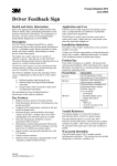
3M™ Driver Feedback Sign DFS 700 Model
3MTM Driver Feedback Signs (DFS) are known as
effective speed calming tools for traffic authorities.
With the new DFS 700 model 3M offers state-of-the-art
three-color LED display technology for informing
drivers about their vehicle’s speed and reminding them
of the given speed limit.
Vehicle speeds that are measured by the integral
microwave radar are displayed and logged for
analysing the speed reduction in order to confirm the
effectiveness of the DFS.
Driver feedback signs are used on road sections where
compliance with the posted speed limit is essential for
traffic safety and quality of life. Example locations are:
Product Features
Speed Transitions
Various Operating Modes
Buy much more than a speed feedback display
• Residential areas
a.
Radar Mode for real-time speed information
• Areas with speed limits
b.
Limit Mode for displaying speed limit only
• Work zones
c.
Covert Mode for measuring speed without feedback
(useful for effectiveness studies)
d.
Demo Mode for demo and inspection of display color,
brightness, and flashing
• City entrances
Accident Sites
• Dangerous curves
• Bridges
Three-colour LED Display
Display a clearer message to drivers
• Tunnels
a.
Intuitive colors: green for within speed limit, amber for
caution and red for warning – exceeding the speed
limit
• School zones
b.
Flashing display for additional warning
• Near old people’s homes
c.
2 ½ digits for speeds up to 199 and readable from
100 m and more (for optimal conditions)
d.
13-segment digits for better readability as compared
to common 7-segment digits
e.
Brightness adaptation to ambient light for better
readability
Vulnerable Road User Congregations
• Hospitals
• Factory premises
• University grounds
Locations with Environmental Issues
• Noisy roads
• Polluted areas
Technical Information DFS 700 / 04.2009
1
Display Range Setting
Define the speed range to react to
Diagnostic Functions
Easily verify proper operability of your DFS
a.
Limit the highest shown speed to prevent misuse
like intentional speeding
a.
b.
Limit the lowest shown speed to avoid the
detection of pedestrians or bicycles
Diagnostic check verifies data memory integrity,
supply voltage, radar operation, GSM communication,
Bluetooth comm. etc.
b.
Self diagnostic check is executed at startup, at
midnight or on user demand
c.
Status codes indicate component status
High Visibility
Catch driver attention anytime
a.
Increased sign visibility at night due to 3M
Diamond Grade reflective sheeting
Speed Data Analysis
Download and analyse speed data with software
b.
Combinable with DG coated backboard for
additional static messages
a.
Measure traffic volume and speed at a location
b.
Create overview tables and several graphical charts
with just a few mouse clicks
Various Power Options
Provide power to DFS anywhere
c.
Create before & after studies to determine speed
reduction effectiveness of DFS
a.
Operate with line power using power supply unit,
e.g. for fixed installations
d.
Identify periodically speeding individuals
b.
Operate with one or two optional 17Ah batteries
for mobile applications
c.
Operate with battery buffered line power using
optional charger in locations with temporary only
line power (e.g. street lamp)
Weekday Scheduling
Define on/off time schedules per weekday
a.
Prevent habituation of drivers and increase credibility
by activating the DFS only when needed, e.g. at
school time in front of school
b.
Save power to increase battery time and increase
LED life-time
Various Communication Options
Communicate with DFS from any distance
a.
USB cable for local data link to PC
b.
Bluetooth for wireless link to PC or PDA
c.
Optional GSM for long distance wireless data
connection from your office (requires data SIM
card from local GSM provider)
User Friendly Design
Save cost and time for installation and use
a.
Lightweight design (DFS only 8,5 kg) for transport and
mounting by one person
b.
Software user interface design for highest user
friendliness
Various Installation Options
Install DFS as you need
c.
Optional battery & mounting box for a professional
installation to different post diameters (60 – 140 mm)
a.
Use DFS unit stand alone for fixed installations
and connected to line power
d.
Safe and secure storage of accessories in optional
battery & mounting box
b.
Use optional mounting box for mobile installations
and to protect accessories
c.
Detach display from frame for integration in
customized static sign board or cabinet
High Quality Standard
Trust in highest reliability
a.
Closed design ensures protection against humidity
and dust
SMS Notification (with optional GSM)
Let the DFS tell you when it needs attention
b.
Self diagnostic functions allow quick verification of
operability
a.
SMS on low (battery) voltage
c.
b.
SMS when memory almost full or full and old data
about to be overwritten
SMS notification function informs you about service
needs (with GSM option)
c.
SMS when diagnostic check identifies defect
Technical Information DFS 700 / 04.2009
2
Included Components
Optional Accessories
The DFS 700 main unit is delivered as plug-and-play
device including all needed components to directly
operate and install it. Only the tools and qualified
people for mounting, connecting with the
corresponding power supply and commissioning the
device have to be provided. The package of the main
unit contains the following parts:
Different optional accessories can be purchased separately
according to the specific needs of the customer and the
application.
• Power supply unit for converting 230 Volt AC line power
to 12 Volt DC for DFS 700
• CD with PC and PDA software and DFS 700
installation and user manual. Also a USB cable
and a Bluetooth stick for PC USB port
• 17 Ah lead-gel battery with cable and polarity protected
connector. Up to two such batteries can be connected
to a DFS 700
One power supply has to be chosen from the
optional accessories!
• Lockable battery & mounting box for storing
accessories and mounting the DFS to poles of 60
to 140 mm diameter
• Battery charger for charging the battery either directly or
through the DFS
• GSM/GPRS modem for long distance comm. over 900
and 1800 MHz GSM networks
Technical Information DFS 700 / 04.2009
3
Technical Data
Dimensions & Weight
660 x 770 x 110 mm (w x h x d), 8,5 kg
Radar Frequency
24,15 GHz – 24,25 GHz
Operating Voltage
11,3 V – 15,0 V
Radar Power
20 dBm, 100 mW e.i.r.p.
Current (Power)
Standby 0,02 A (0,24W)
Radar mode w/o traffic (display inactive)
0,08 A (0,96 W)
Radar mode with traffic (display active, one color @med
brightness) 1,00 A (12 W)
Peak current (less than 1 second with all components on)
5 A (60 W)
Radar Speed Range and Accuracy
Measures from 3 km/h to 199 km/h (can be limited)
± 2 km/h for speeds below 100 km/h
± 2 % for speeds above 100 km/h
Radar Detection Range
Approximately 100m for avg. 4-seat sedan
Radar Beam Width
14° horizontal, 24° vertical
Power Supply Unit*
Input 100 V – 240 V AC @ 50 – 60 Hz
Protection class 1
Output 12 V / 100 W
IP 55, ca. 2 kg
Bluetooth
Class 2 module, 4dBm transmission power, up to 20 m
range
Interfaces
USB, Bluetooth, Charger input, Battery 1 input (charged
when charger connected), Battery 2 input, Power switch,
RS-232 (for GSM Modem), GSM power supply,
Switchgear for ext. devices, Grounding bolt
Battery Standby Time
Approx. 850 hours using one completely charged 17 Ah
battery
Fuse
ATO Fuse 4A T
Switchgear
24 VAC / DC, 150 mA, connector type Weidmüller BLZF
3.5/3/F SNOR
Cabinet Rating
IP 54
Firmware
Flashable
Cabinet Color
7042 RAL
Software
DFS-CAS for Windows 2000/XP PC
DFS-CAS for Windows Mobile 5.0 PDA
Sign Face
White Diamond Grade™ reflective sheeting
Printable area 530 x 290 mm (w x h)
GSM Modem*
Wavecom 900 MHz / 1800 MHz
(requires SIM card with Circuit Switched Data Services
from local GSM provider), ca. 0,25 kg
Temperature Range
–35 to + 75 °C (DFS 700 internal temp.)
Humidity Range
Up to 95 %
Batteries*
12 V, 17 Ah, ca. 6kg
Display
330 mm high, 450 mm wide
2 ½-digits (speed up to 199), 13 segments
Battery Charger*
100 V – 240 V AC @ 50 – 60 Hz
Protection class 2
Max output 12 V / 60 W
Temperature range - 40° to +40°
IP 67, ca. 1kg
LEDs
InGaAIP SMD LEDs, viewing angle 16 – 18°
3 rows green (570 nm), 3 rows red (635 nm)
Backup Battery
Lithium 3V CR2450, ca. 2 years lifetime
Battery & Mounting Box*
For 60 to 140 mm pole diameters, ca. 7,5 kg
Data Memory
1 MB non-volatile flash memory
100.000 data entries
* optionally available accessories
Technical Information DFS 700 / 04.2009
4
DFS 700 EU Standards Compliance
Device
Standard (Directive / Council Recommendation)
DFS 700
EN 50293 (89/336/EEC EMC Directive) Electromagnetic compatibility - Road traffic signal systems Product standard
DFS 700
EN 300 440-2 (99/5/EC R&TTE Directive) Electromagnetic compatibility and Radio spectrum Matters
(ERM); Short Range devices; Radio equipment to be used in the 1 GHz to 40 GHz frequency range; Part
2:Harmonized EN under article 3.2 of the R&TTE Directive
DFS 700
EN 60950 / EN 60215 (73/23/EEC Low Voltage Directive) Safety of information technology equipment
including electrical business equipment / Safety requirements for radio transmitting equipment
DFS 700
Radar Unit
EN 301 489-3 (99/5/EC R&TTE Directive) Electromagnetic compatibility and Radio spectrum Matters
(ERM): ElectroMagnetic Compatibility (EMC) standard for radio equipment and services; Part 3: Specific
conditions for Short-Range Devices (SRD) operating on frequencies between 9 kHz and 40 GHz
EN 50392 (99/519/EC EMF Recommendation) Generic standard to demonstrate the compliance of
electronic and electrical apparatus with the basic restrictions related to human exposure to
electromagnetic fields (0 Hz - 300 GHz)
DFS Bluetooth EN 301 489-17 (99/5/EC R&TTE Directive) Electromagnetic compatibility and Radio spectrum Matters
Module
(ERM): ElectroMagnetic Compatibility (EMC) standard for radio equipment and services; Part 17: Specific
conditions for 2,4 GHz wideband transmission systems and 5 GHz high performance RLAN equipment
EN 300 328 (99/5/EC R&TTE Directive) Electromagnetic compatibility and Radio spectrum Matters
(ERM); Wideband Transmission systems; Data transmission equipment operating in the 2,4 GHz ISM
band and using spread spectrum modulation techniques;
Harmonized EN covering essential requirements under article 3.2 of R&TTE Directive
EN 50392 (99/519/EC EMF Recommendation) Generic standard to demonstrate the compliance of
electronic and electrical apparatus with the basic restrictions related to human exposure to
electromagnetic fields (0 Hz - 300 GHz)
DFS 700 GSM EN 301 489-7 (99/5/EC R&TTE Directive) Electromagnetic compatibility and Radio spectrum Matters
Modem*
(ERM): ElectroMagnetic Compatibility (EMC) standard for radio equipment and services; Part 7: Specific
conditions for mobile and portable radio and ancillary equipment of digital cellular radio
telecommunications systems (GSM and DCS)
EN 301 511 (99/5/EC R&TTE Directive) Global System for Mobile communications (GSM); Harmonized
standard for mobile stations in the GSM 900 and DCS 1800 bands covering essential requirements under
article 3.2 of the R&TTE directive (1999/5/EC)
EN 50392 (99/519/EC EMF Recommendation) Generic standard to demonstrate the compliance of
electronic and electrical apparatus with the basic restrictions related to human exposure to
electromagnetic fields (0 Hz - 300 GHz)
99/5/EC R&TTE Directive
Directive of 9 March 1999 of the European Parliament and of the Council on Radio Equipment and Telecommunications
Terminal Equipment and the mutual recognition of their conformity
89/336/EEC EMC Directive
Council Directive of 3 May 1989 on the approximation of the laws of the Member States relating to electromagnetic
compatibility
73/23/EEC Low Voltage Directive
Council Directive of 19 February 1973 on the harmonisation of the laws of Member States relating to Electrical Equipment
designed for use within certain voltage limits
99/519/EC EMF Recommendation
Council Recommendation of 12 July 1999 on the limitation of exposure of the general public to ElectroMagnetic fields (0 Hz
to 300GHz)
Technical Information DFS 700 / 04.2009
5
3M UK PLC
Traffic Safety Systems Division
3M Centre
Cain Road
Bracknell
Berkshire
RG12 8HT
Copyright © 3M 2009