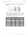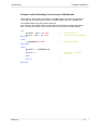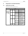
1
JX3-BN-CAN
JetWeb
Peripheral Module
User Manual
Article no.: 608 721 35
Edition: 1.03.2
October 2007 / Printed in Germany
Introduction
JetWeb
Edition 1.03.2
Jetter AG reserves the right to make alterations to its products in the interest of technical
progress. These alterations need not be documented in every single case.
This User Manual and the information contained herein have been compiled with due
diligence. However, Jetter AG assume no liability for printing or other errors or damages
arising from such errors.
The brand names and product names used in this document are trademarks or registered
trademarks of the respective title owner.
2
Jetter AG
JX3-BN-CAN
Introduction
How to Contact us:
Jetter AG
Gräterstraße 2
D-71642 Ludwigsburg
Germany
Phone - Switchboard:
Phone - Sales:
Phone - Technical Hotline:
+49 7141 2550-0
+49 7141 2550-433
+49 7141 2550-444
Fax - Sales:
E-mail - Sales:
E-mail - Technical Hotline:
+49 7141 2550-484
[email protected]
[email protected]
This User Manual belongs to the
JX3-BN-CAN:
Type:
Serial #:
Year of construction:
Order #:
To be entered by the customer:
Inventory #:
Place of operation:
© Copyright 2007 by Jetter AG. All rights reserved.
Jetter AG
3
Introduction
JetWeb
Significance of this User Manual
This User Manual is part of the JX3-BN-CAN and
•
•
and must be kept in a way that it is always at hand until the JX3-BN-CAN will be
disposed
the JX3-BN-CAN must be handed over, if it is sold, alienated, or loaned
Please contact the manufacturer in any case you encounter difficulties to clearly
understand this User Manual.
We would appreciate any suggestions and contributions on your part and would ask you
to contact us. This will help us to produce manuals that are more user-friendly and to
address your wishes and requirements.
This User Manual contains important information on how to transport, erect, install,
operate, maintain and repair the JX3-BN-CAN.
Therefore, the persons carrying out these jobs must carefully read, understand and
observe this User Manual, and especially the safety instructions.
Missing or inadequate knowledge of the User Manual results in the loss of any claim of
liability on part of Jetter AG. Therefore, the operating company is recommended to have
the instruction of the persons concerned confirmed in writing.
History
4
Edition
Comment
1.03.1
Original issue
1.03.2
Changes, see Recent Revisions (on page 38)
Jetter AG
JX3-BN-CAN
Introduction
Description of Symbols
This sign is to indicate a possible impending danger of serious physical damage or
death.
Warning
This sign is to indicate a possible impending danger of light physical damage. This sign
is also to warn you of material damage.
Caution
This sign indicates hazard of life due to electric shock caused by a high operating
voltage.
Warning
This sign is to indicate hazard of serious physical damage or death due to accidentally
touching dangerous parts of the device.
Warning
You are asked to wear goggles. Failure to comply may lead to bodily injuries.
Warning
This sign is to warn you of material damage due to applying hard blows or shocks to the
motor flange and shaft.
This sign is to indicate a possible impending situation which might bring damage to the
product or to its surroundings.
It also identifies requirements necessary to ensure faultless operation.
Important
Jetter AG
5
Introduction
JetWeb
You will be informed of various possible applications and will receive further useful
suggestions.
It also gives you words of advice on how to efficiently use hardware and software in
order to avoid unnecessary efforts.
Note
·/-
Enumerations are marked by full stops, strokes or scores.
Operating instructions are marked by this arrow.
Automatically running processes or results to be achieved are marked by this arrow.
PC and user interface keys.
Reference to a program or file.
This symbol informs you of additional references (data sheets, literature, etc.)
associated with the given subject, product, etc. It also helps you to find your way around
this manual.
6
Jetter AG
JX3-BN-CAN
Contents
Contents
1
Safety Instructions
1.1
1.2
1.3
2
3
5
6
22
Register Array for JX3 Modules .........................................................................................22
Indirect Access to JX3 Module Registers ..........................................................................25
Diagnostics and Administration
6.1
6.2
6.3
6.4
6.5
18
Technical Data ...................................................................................................................18
Description of Connections ................................................................................................18
Module Numbering.............................................................................................................20
Register Addressing
5.1
5.2
16
Technical Data ...................................................................................................................16
Description of Connections ................................................................................................16
Meaning of LEDs ...............................................................................................................17
Module Register for the Logic Voltage of the JX3 Modules...............................................17
Jetter System Bus Connections
4.1
4.2
4.3
13
Product Description JX3-BN-CAN .....................................................................................13
Minimum Requirements .....................................................................................................14
Scope of Delivery...............................................................................................................14
Document Survey ..............................................................................................................15
Power Supply
3.1
3.2
3.3
3.4
4
Generally Valid Safety Instructions ......................................................................................9
1.1.1
Usage to the Intended Purpose .............................................................................9
1.1.2
Non-Intended Use..................................................................................................9
1.1.3
Who may Operate the Device? ...........................................................................10
1.1.4
Modifications and Alterations to the Module........................................................10
1.1.5
Repair and Maintenance......................................................................................10
1.1.6
Decommissioning and Disposal ..........................................................................10
Ensure Your Own Safety ...................................................................................................11
1.2.1
Malfunctions.........................................................................................................11
1.2.2
Information Signs and Labels ..............................................................................11
Instructions on EMI ............................................................................................................11
Introduction
2.1
2.2
2.3
2.4
9
28
Diagnostics by LEDs..........................................................................................................28
Diagnostics by JX3 Module Registers ...............................................................................29
Connection Monitoring at the Jetter System Bus...............................................................32
Connection Monitoring by the JX3 System Bus.................................................................34
Electronic Data Sheet (EDS) .............................................................................................34
7
Recent Revisions
38
8
Survey of Module Registers
39
Jetter AG
7
Contents
9
Design
9.1
9.2
10
JetWeb
Physical Dimensions..........................................................................................................40
Connections .......................................................................................................................41
Operating Conditions
10.1
10.2
10.3
10.4
40
42
Environment and Mechanics..............................................................................................42
Enclosure ...........................................................................................................................43
Direct Current Input Connectors and Output Connectors..................................................44
Shielded Data and I/O Lines ..............................................................................................45
11
Glossary General
46
12
Glossary Peripherial Modules
50
13
List of Illustrations
52
14
Index
53
8
Jetter AG
JX3-BN-CAN
1 Safety Instructions
1
Safety Instructions
1.1
Generally Valid Safety Instructions
The device complies with the valid safety regulations and standards. Special emphasis
was given to the safety of the users.
Further, the user should adhere to the following regulations:
•
•
•
1.1.1
relevant accident prevention regulations;
accepted safety rules;
EC guidelines and other country-specific regulations.
Usage to the Intended Purpose
Usage to the intended purpose includes operation in accordance with the User Manual.
The JX3-BN-CAN module is for remote connection of JX3 expansion modules to all
controllers of the JetControl series. Up to 8 expansion modules can directly be connected
to the JX3-BN-CAN bus head. By means of a JX3-PS1 module, eight further JX3
modules can be connected.
The supply voltage of the JX3-BN-CAN module is DC 24 V. This operating voltage is
classified as SELV (Safety Extra Low Voltage). The JX3-BN-CAN module is therefore not
subject to the EU Low Voltage Directive.
The JX3-BN-CAN module may only be operated within the limits of the stated data.
The device is used to control machinery, such as conveyors, production machines, and
handling machines.
1.1.2
Non-Intended Use
The device must not be used in technical systems which to a high degree have to be failsafe, e.g. ropeways and aeroplanes.
If the device is to be run under ambient conditions which differ from the conditions
mentioned in chapter Operating Conditions (on page 42), the manufacturer is to be
contacted beforehand.
Jetter AG
9
1.1 Generally Valid Safety Instructions
1.1.3
JetWeb
Who may Operate the Device?
Only instructed, trained and authorised persons are permitted to operate this device.
Transport:
Installation:
Commissioning:
1.1.4
Only by personnel with knowledge in handling
electrostatically sensitive components.
Only by specialists with training in electrical
engineering.
Only by specialists with extensive knowledge of, and
experience with, electrical engineering / drive
technology.
Modifications and Alterations to the Module
For safety reasons, no modifications and changes to the device and its functions are
permitted.
Any modifications to the device not expressly authorised by the manufacturer will result in
a loss of any liability claims to Jetter AG.
The original parts are specifically designed for the device. Parts and equipment of
other manufacturers are not tested on our part, and are, therefore, not released by
us.
The installation of such parts may impair the safety and the proper functioning of the
device.
Any liability on the part of Jetter AG for any damages resulting from the use of non
original parts and equipment is excluded.
1.1.5
Repair and Maintenance
This device must not be repaired by the operators themselves. The device does not
contain any parts that could be repaired by the operator.
The device must be sent to Jetter AG for repair.
1.1.6
Decommissioning and Disposal
The environmental regulations for the respective country apply to decommissioning and
disposing of devices on the operating company’s premises.
10
Jetter AG
JX3-BN-CAN
1.2
1 Safety Instructions
Ensure Your Own Safety
Isolate the JX3-BN-CAN module from the mains, if maintenance works have to be
carried out. By doing so, you will prevent accidents resulting from electric voltage
and moving parts.
Warning
Safety and protective devices, e.g. the barrier and cover of the terminal box must
never be shunted or by-passed.
Dismantled protective equipment, such as the fuses must be reattached prior to
commissioning and checked for proper functioning.
Prior to commissioning, the machine manufacturer shall conduct a hazard analysis
for the machine and take appropriate measures to prevent personal injury and
damage to property resulting from accidental movements.
1.2.1
Malfunctions
In case of failures or damages, disconnect the device from the mains
immediately.
Malfunctions or other damages are to be reported to an authorised person at
once.
The device must be protected from improper or inadvertent use.
1.2.2
Information Signs and Labels
Writings, information signs, and labels always have to be observed and kept
readable.
Damaged or unreadable information signs and labels have to be exchanged.
1.3
Instructions on EMI
The noise immunity of a system corresponds to the weakest component of the system.
For this reason, correct wiring and shielding of cables is of paramount importance.
Jetter AG
11
1.3 Instructions on EMI
JetWeb
Important!
Measures for increasing immunity to interfering in electric plants:
The JX3-BN-CAN module has to be attached to a DIN rail acc. to EN 50022-35
x 7.5.
Follow the instructions given in Application Note 016 "EMC-Compatible
Installation of the Electric Cabinet" published by Jetter AG.
The following instructions are excerpts from Application Note 016:
On principle, physical separation should be maintained between signal and
power lines. We recommend spacings greater than 20 cm. Cables and lines
should cross each other at an angle of 90°.
Shielded cables must be used for the following lines:
Analog lines, data lines, motor cables coming from inverter drives (servo output
stage, frequency converter), lines between components and interference
suppressor filter, if the suppressor filter has not been placed at the component
directly.
Shield cables at both ends.
Unshielded wire ends of shielded cables should be as short as possible.
The entire shield has, in its entire perimeter, be drawn behind the isolation,
and then be clamped under an earthed strain relief with the greatest possible
surface area.
12
Jetter AG
JX3-BN-CAN
2 Introduction
2
Introduction
2.1
Product Description JX3-BN-CAN
Via the module JX3-BN-CAN, the JX3 expansion modules can be connected to all
controllers of the JetControl series as remote manuals. Up to 8 expansion modules can
directly be connected to the JX3-BN-CAN bus head. By means of a JX3-PS1 module,
eight further JX3 modules can be connected.
Product Description JX3-BN-CAN
Article #
10000544
Module code
30
LED-display
Connection X18
Supply voltage
Communication of the JX3 system bus
Connection to the Controller
BUS-IN Jetter system bus
Connection X19
BUS-OUT Jetter system bus
Connection X10
Power supply for logic circuit
Connection X119
8 modules can be connected directly, 8 further
modules via a JX3-PS1 module
Baud rate, address, bus termination: automatically
Configuration of the
Jetter system bus
Jetter AG
13
2.2 Minimum Requirements
2.2
JetWeb
Minimum Requirements
The functions described in this document have got minimum requirements on modules,
controllers and software. They have been listed in the following table.
System Requirements
Controller / Software
2.3
Starting from Software Release
JC-24x
V 3.23
JX6-SB / JX6-SB-I
V 2.18
JC-647
V 3.50
JetSym
V 3.00
JM-D203-JC-24x
V 1.12
Scope of Delivery
Scope of Delivery JX3-BN-CAN
Article #
14
Quantity
Description
10000544
1
JX3-BN-CAN
60870409
1
60870411
10
60871026
1
BU_02_BLZF_SW_RM3.5
2-pin female connector, contact spacing 3.5 mm
DIV_DEK_5/5_MC-10_NEUT._WS
Terminal markers
Installation Instructions
Jetter AG
JX3-BN-CAN
2.4
2 Introduction
Document Survey
Document Survey of the JX3-I/O System
JX3-I/O System, User Information
JX3-BN-CAN, Installation Manual
Document Survey of the JX2-I/O System
JX2-I/O System, User Information
SysBus_Configuration_xxx_e.xls
Configuration aid for the Jetter system bus: The file can be processed in
Microsoft Excel directly.
xxx: Version index
Jetter AG
15
3.1 Technical Data
JetWeb
3
Power Supply
3.1
Technical Data
Power supply has to be made through a 24 V DC power supply unit with SELV output.
The power supply must meet the following requirements:
Power Supply Unit Requirements
Rated voltage
DC 24 V
Voltage range
-15 % ... +20 %
Filtering of the residual ripple
<5%
Power consumption
0.5 A x 24.0 V = 12 W max.
The JX3-BN-CAN module generates several internal supply voltages out of the
connected voltage supply. If all internal supply voltages are ok, the R-LED is lit green.
3.2
Description of Connections
Assignment of Terminal X10
View
Pin
X10.DC24 V
X10.0V
16
Signal
+ 24 V
0V
Comment
Supply voltage
Reference potential
Jetter AG
JX3-BN-CAN
3.3
3 Power Supply
Meaning of LEDs
Module JX3-BN-CAN has been equipped with four LEDs. The LEDs R and E indicate the
status of the voltage supply.
LEDs
View
LED
Color
Status
Function
R
green
Off
At least one internal power
supply is not ok
All internal voltage
supplies are ok
No error
is lit
E
3.4
red
Off
Module Register for the Logic Voltage of the
JX3 Modules
The JX3-BN-CAN module internally generates three different kinds of voltages. The
voltage of the logic supply of the JX3 modules can be read via module register 10.
Voltage of the JX3 Module Logic Supply
Module Reg.
Description
Access
Value Range
Value After Reset
Jetter AG
10
The JX3-BN-CAN module supplies the connected JX3
modules with a 5 V logic voltage.
Read only
0 ... 5,500 [Millivolt]
5,000, typical
17
4.1 Technical Data
JetWeb
4
Jetter System Bus Connections
4.1
Technical Data
The JX3-BN-CAN module can be integrated into the Jetter system bus directly via the
connections BUS-IN X18 and BUS-OUT X19.
Technical Data
4.2
Setting the module number
automatically
Setting the baud rate
automatically
Bus terminating resistor
automatically
Description of Connections
Assignment of Terminal X18
View
18
Pin
Signal
1
CMODE0
2
CL
3
GND
4
CMODE1
5
TERM
6
unassigned
7
CH
8
unassigned
9
do not connect
Comment
internally shunted by
X18.3
Jetter AG
JX3-BN-CAN
4 Jetter System Bus Connections
Assignment of Terminal X19
View
Pin
Signal
1
CMODE0
2
CL
3
GND
4
CMODE1
5
TERM
6
unassigned
7
CH
8
unassigned
9
do not connect
Comment
Important!
For deactivating the internal bus terminating resistor, pin X19.5 must be connected with pin
X19.3 at JX3-BN-CAN.
In original Jetter AG connection cables for the Jetter system bus, pin 3 has been shunted
by pin 5 in the connector.
Jetter AG
19
4.3 Module Numbering
4.3
JetWeb
Module Numbering
At numbering the modules at the Jetter system bus, the I/O module number and the slave
module number are differentiated. The module number is part of the coding for input and
output numbers, as well as for the register numbers of the expansion modules, which are
connected to the Jetter system bus.
I/O Module Number
An I/O module number is not assigned to all non-intelligent JX2 modules and all JX3
modules. I/O module numbers are assigned according to the following rules:
•
•
•
•
•
I/O module number 1 is always assigned to the controller.
I/O module number 2 is assigned to the first non-intelligent JX2, respectively JX3
module connected to the Jetter system bus.
The modules JX2-PS1 and JX3-PS1 are not counted.
Intelligent JX2 modules are not counted.
The first JX3-BN-CAN connected to the Jetter system bus is assigned to I/O module
number 33.
Slave Module Number
A slave module number is assigned to all intelligent JX2 modules and JetMove motion
systems. Slave module numbers are assigned according to the following rules:
•
•
•
The controller is always assigned to slave module number 1.
The first intelligent JX2 module connected to the Jetter system bus is assigned to
slave module number 2.
Non-intelligent JX2 and JX3 modules are not counted.
Example: Module Numbering
In this example, various expansion modules have been connected with a JC-24x. The I/O
module numbers are shown above, the slave module numbers below the modules.
20
Jetter AG
JX3-BN-CAN
4 Jetter System Bus Connections
Figure 1: Module numbering in the Jetter system bus
Survey of the Module Numbers
Jetter AG
Module
I/O Module Number
Slave Module Number
JC-24x
JX2-ID8
JX2-ID8
JX2-SM2
JX3-BN-CAN
JX3-DIO16
JX3-DI16
JX2-PS1
JX2-ID8
JX2-ID8
JX2-SM2
JX3-BN-CAN
JX3-DIO16
JX3-DI16
JX3-DI16
1
2
3
33
4
5
6
7
34
8
9
10
1
2
3
-
21
5.1 Register Array for JX3 Modules
JetWeb
5
Register Addressing
5.1
Register Array for JX3 Modules
Each JX3 module is equipped with over 10,000 module registers. The module registers,
on the other hand, have been assigned to the controller registers. By means of registers,
process, configuration and diagnose data can be read by module JX3-BN-CAN,
respectively written to the module.
Registers can be accessed directly in the application program of the controller, in a setup
window of JetSym, or via the user interface directly.
Register number
3
0
0
z
Module register number
The meaning depends on the module
Register prefix
The meaning depends on the controller
The register number results from a register prefix and a module register number. The
register prefix depends on the position of the JX3-BN-CAN module in the Jetter system
bus, and on the controller that is applied.
At determining the register prefixes, the following parameters have to be considered:
•
•
•
22
Controller (JC-24x, JC-64x, JC-800, JM-D203-JC-24x)
Submodule position (at JX6-SB, JX6-SB-I)
I/O module number in the Jetter system bus
Jetter AG
JX3-BN-CAN
5 Register Addressing
JX3-I/O-modules connected to JC-24x and JM-D203-JC-24x
3
x
x
z
Module register number: 0...9
I/O module number
in the Jetter system bus - 2: 0...61
JX3-I/O module array: 3
JX3-I/O modules connected to JX6-SB(-I) and JC-647
3
m
0
3
x
x
z
Module register number: 0...9
I/O module number
in the Jetter system bus - 2: 0...61
I/O module range: 03
Submodule position: 1...3
Array: 3
JX3-I/O modules connected to JX6-SB(-I) and JC-800
4
C
M
0
3
x
x
z
Module register number: 0...9
I/O module number
in the Jetter system bus - 2: 0...61
I/O module range: 03
System bus module: 1...2
Module board number: 1...3
Array: 4
Jetter AG
23
5.1 Register Array for JX3 Modules
JetWeb
Example: Register and I/O Addressing of a JX3 Module in the Jetter
System Bus
Six modules, JX3-BN-CAN (33, 34), JX3-DI16 (2, 4) and JX3-DIO16 (3, 5), have been
connected to a JC-24x controller. The register and I/O numbers listed in the table below
result from the module position in the Jetter system bus.
•
•
•
In the Jetter system bus, no I/O numbers have been assigned to the JX3-BN-CAN.
The first JX3-BN-CAN connected to the JetControl is assigned the I/O module
number 33.
The first JX3 module is assigned I/O module number 2.
Register and I/O Numbers
24
I/O Module Number
Module
Register Number
I/O Numbers
1
JC-24X
101 ... 116
33
JX3-BN-CAN
0 ... 1999
20000 ... 49999
3310 ... 3319
02
JX3-DI16
3000 ... 3009
201 ... 216
03
JX3-DIO16
3010 ... 3019
301 ... 316
34
JX3-BN-CAN
3320 ... 3329
04
JX3-DI16
3020 ... 3029
401 ... 416
05
JX3-DIO16
3030 ... 3039
501 ... 516
-
Jetter AG
JX3-BN-CAN
5.2
5 Register Addressing
Indirect Access to JX3 Module Registers
Each JX3 module is equipped with over 10,000 module registers. One index and one
data register make access to all 10,000 module registers possible.
Figure 2: Indirect register access to JX3 modules
Above, indirect access to the JX3 module registers (2) has been illustrated. In the Jetter
system bus, the JX3 modules can be accessed via register numbers 3xxz (1). At indirect
access, the number of the JX3 module register is written to 3xx7. After this, the content of
the JX3 module register can be accessed via 3xx8.
Register Numbering Dependent on the Controller
•
•
•
For JC-24x controllers: Register number 3xxz
For JC-647 controllers: Register number 3m03xxz
For JC-800 controllers: Register number 4CM03xxz
Indirect Register Access in the Application Program
•
Jetter AG
Indirect access to JX3 module registers of a module may only be carried out within a
task. If indirect access is made out of several tasks, the index may be overwritten
after a task change.
25
5.2 Indirect Access to JX3 Module Registers
JetWeb
Index for Indirect Register Access
Module Register
Description
Access
Value Range
Value After Reset
Comment
7
At indirect register access to JX3 modules, the index contains
the module register number. It functions as a pointer.
read and write access
0 ... 9999
9
After switching on, the index points to the module register
"operating system version".
Data for Indirect Register Access
Module Registers
Description
Access
Value Range
Value After Reset
8
This module register is for reading, respectively writing, the
value of the selected module register.
The JX3-BN-CAN module copies the value of the actual
module register to this register.
Read and write access
32 bits
Operating System Release
Example: Directly Checking Communication with the JX3 Modules
In a JX3-BN-CAN module, communication with the connected JX3 modules is to be
checked. For this, bit 15 in register 0 the status of the JX3-BN-CAN must be queried.
VAR
nm_State : INT at %vl 3310;
END_VAR;
//
Status register JX3-BN-CAN
//
Bit number
//
Communication active
//
...
CONST
c_ComActive = 15;
END_CONST;
TASK 0
WHEN
BIT_SET (nm_State, c_ComActive)
CONTINUE;
END_TASK;
26
Jetter AG
JX3-BN-CAN
5 Register Addressing
Example: Indirect Reading of the Connected JX3 Modules
The number of JX3 modules connected to a JX3-BN-CAN is to be read. The number of
connected JX3 modules has been written to module register 256 of the JX3-BN-CAN.
The JX3-BN-CAN has got I/O module number 33.
As a first step, JX3 module register number 256 has to be written into the index register.
As a next step, the number of connected modules can be read via the data register.
VAR
nm_Index : INT at %vl 3317;
nm_Data : INT at %vl 3318;
END_VAR;
//
//
Index register
Data register JX3-BN-CAN
//
Parameter number
//
there are no modules
connected
//
...
CONST
c_RegNumModules = 256;
END_CONST;
TASK 0
nm_Index := c_RegNumModules;
IF
nm_Data = 0
THEN
// ...
END_IF;
END_TASK;
Jetter AG
27
6.1 Diagnostics by LEDs
JetWeb
6
Diagnostics and Administration
6.1
Diagnostics by LEDs
Module JX3-BN-CAN has been equipped with four LEDs.
LEDs
View
LED
Color
Status
Function
R
green
Off
At least one internal power
supply is not ok
All internal voltage
supplies are ok
No error
At least one internal power
supply is not ok
At least one error bit has
been set in the status
module register.
The JX3-BN-CAN module
is waiting for setup by the
controller
The connection to the
controller via the Jetter
system bus is active
is lit
E
red
Off
flashing
is lit
D1
red
flashing fast
Off
D2
red
flashing fast or
slowly
flashing fast
flashing slowly
E, D1,
D2
28
red
jointly flashing
There is no valid operating
system available on the
JX3-BN-CAN module.
Carry out the update.
The JX3-BN-CAN module
is waiting for setup by the
controller
The connection to the
controller via the Jetter
system bus is active.
The operating system
update is active.
Jetter AG
JX3-BN-CAN
6.2
6 Diagnostics and Administration
Diagnostics by JX3 Module Registers
Status of JX3-BN-CAN
Module Register
Description
Access
Value Range
Value After Reset
0
The JX3-BN-CAN module reads the error bit statuses of all
connected JX3 modules in cyclic mode.
If in at least one connected JX3 module an error bit has been
set, the corresponding collective error bit is set in the status
module register.
Read
16 bits, bit-coded
Present state
The meaning of the individual bits in the status module register:
Bit 0:
Bit 1:
Bit 2:
Bit 8:
Bit 9:
Collective error bit 0 of the connected JX3 modules
0=
Error bit 0 has not been set
1=
At least one error bit 0 has been set
Collective error bit 1 of the connected JX3 modules
0=
Error bit 1 has not been set
1=
At least one error bit 1 has been set
Collective error bit 2 of the connected JX3 modules
0=
Error bit 2 has not been set
1=
At least one error bit 2 has been set
Exceeding the time limit at cyclic data exchange
0=
Time has not been exceeded
1=
Time has been exceeded
0=
This error can only be fixed by restarting the Jetter system bus.
Fatal error at cyclic data exchange
0=
No error
1=
Fatal error
This error can only be fixed by restarting the Jetter system bus.
Bit 15:
Cyclic data exchange with the connected JX3 modules
0=
Not active
1=
Activated
This error can only be fixed by restarting the Jetter system bus.
Jetter AG
29
6.2 Diagnostics by JX3 Module Registers
JetWeb
The error bits of the individual JX3 modules are always displayed in the JX3 module
register 0. An error bit, respectively a collective error bit remains only set as long as the
cause of the error exists.
Operating System Release
Module Register
Description
Access
Value Range
Value After Reset
Comment
9
The operating system release of the JX3-BN-CAN module in
the "Major.Minor.Branch.Build" format
Read
32 bits
Up-to-date operating system release
A released operating system can be recognized by both
Branch and Build having got value zero. For displaying the
operating system release number in the setup window of
JetSym, please select the format "IP address".
Example: Displaying the Operating System Release Number as an IP
Address in the Setup Window
The operating system release number of a JX3-BN-CAN module is displayed in a setup
window of JetSym. The JX3-BN-CAN module has been connected to a JC-24x controller.
The operating system release number can be read via register 3319 (2).
The format "IP address" has to be selected via the context menu of the respective line.
The operating system release number is now displayed with dots as separators.
Figure 3: SW version, displayed in the format of the IP address
The operating system release number 1.3.0.0 (3) is displayed in the variable
st_JX3_BN_CAN.nm_Version (1).
30
Jetter AG
JX3-BN-CAN
6 Diagnostics and Administration
Firmware Version
Module Register
Description
Access
Value Range
Value After Reset
Comment
32
The firmware version is stored to the JX3-BN-CAN module.
The firmware cannot be updated by the user.
Read
32 bits
Up-to-date firmware version
Similar to an IP address, the firmware version is displayed in
the format "Major.Minor.Branch.Build".
A released firmware version can be recognized by both
Branch and Build having got value zero.
For displaying the operating firmware version number in the
setup window of JetSym, please select the format "IP
address".
Amount of Connected JX3 Modules
Module Register
Description
Access
Value Range
Value After Reset
256
Out of this module register, the amount of JX3 modules
connected to the JX3-BN-CAN module can be read.
Read
0 ... 16
Amount of modules presently connected
Example: Evaluating an Error Message by a Diagnostic Register
In the application program of the controller, the error register is monitored. When bit 9
"Error Output Driver" has been set, the first JX3 module having got an error message, is
searched for in a loop. After this, the I/O module number and the number of the status
register is calculated.
VAR
n_ModuleErrorBuffer : INT at %vl 100;
n_Counter : INT at %vl 101;
pn_State : INT at %vl 102;
n_ModuleNumber : INT at %vl 103;
ns_Error : INT at %vl 2008;
ns_ModuleError: INT at %vl 2039;
END_VAR;
//
//
//
//
//
//
Auxiliary register
Auxiliary register
Pointer to diagn. registers
Register for module number
Error register
Diagnostics error register
//
Wait for error
n_ModuleErrorBuffer := ns_ModuleError;
n_Counter := 0;
//
Buffer the error message
WHILE n_Counter < 32 DO
//
Search buffer
TASK t_Main
WHEN
BIT_SET(ns_Error, 9)
CONTINUE;
Jetter AG
31
6.3 Connection Monitoring at the Jetter System Bus
SHIFT_RIGHT(n_ModuleErrorBuffer, 1);
IF
n_ModuleErrorBuffer WAND 0x01
THEN
EXIT;
END_IF;
INC(n_Counter);
END_WHILE;
pn_State := 3000 + (n_Counter * 10);
n_ModuleNumber := n_Counter + 2;
JetWeb
//
Bit 0 = 1
//
-> Module has been found
//
Next module
//
//
Calculate the pointer
Calculate the module number
End_Task;
6.3
Connection Monitoring at the Jetter System
Bus
Between the controller and the JX3-BN-CAN module, telegrams are regularly exchanged
via Jetter system bus. This way, the controller can monitor the connection to the
JX3-BN-CAN module. An interrupted connection can be restored by restarting the Jetter
system bus.
Monitoring Interval for I/O Modules
Register(s)
Description
Access
Value Range
Value After Reset
Comment
32
2028
By means of register 2028, the time interval between two
monitoring telegrams can be set.
The monitoring interval is configured in steps of 10 ms.
0 : no monitoring
1 : Monitoring time 10 ms
2 : etc.
Read / Write
0 ... 255
20 : Monitoring interval 200 ms
Connection monitoring is carried out by the following modules:
• JX2-I/O modules
• JX3 modules via the JX3-BN-CAN module
• Third-party modules
• LioN modules
• LJX7-CSL Compactbox modules
Jetter AG
JX3-BN-CAN
6 Diagnostics and Administration
Monitoring Timeout
Module Register
Description
Access
Value Range
Value After Reset
2
By means of JX3 module register 2, connection monitoring at
the JX3-BN-CAN module can be activated.
The monitoring timeout is configured in steps of 10 ms.
0 : no monitoring
1 : monitoring timeout 10 ms
2 : etc.
Read / Write
0 ... 255
0
At active monitoring, the JX3-BN-CAN module waits for at least one monitoring telegram
transmitted by the controller within the set monitoring timeout. If, within the monitoring
timeout, no monitoring telegram has been received, the JX3 system bus is stopped. The
JX3 modules write the configured error statuses to the outputs.
The monitoring timeout within JX3 module register 2 must be at least twice as big as the
monitoring interval of the I/O modules in register 2028.
Important!
If data exchange within the JX3 system bus has been stopped, the JX3 modules
write the configured error statuses to the outputs.
Modules with a Peripheral Error
Register(s)
Description
Access
Value Range
Value After Reset
Comment
2039
If the controller recognizes a peripheral error at a JX2-I/O
respectively JX3 expansion module, the respective bit is set in
register 2039.
Read / Write
32 bits, bit-coded
0
Only the user is allowed to reset the error by writing zero to
the register.
The Meaning of the Individual Bits in the Peripheral Error Register:
Bit 1:
1=
I/O module 2 reports a peripheral error
Bit 2:
1=
I/O module 3 reports a peripheral error
etc.
Jetter AG
33
6.4 Connection Monitoring by the JX3 System Bus
6.4
JetWeb
Connection Monitoring by the JX3 System
Bus
Between the JX3-BN-CAN and the connected JX3 modules, telegrams are regularly
exchanged via JX3 system bus. The bus head JX3-BN-CAN and the JX3-BN-CAN
module can detect an interrupted connection this way. An interrupted connection can be
restored by restarting the JX3 system bus.
Occasionally, the JX3-BN-CAN bus head stops data exchange with the connected JX3
modules.
•
•
The JX3-BN-CAN bus head is not connected with the superordinate controller any
more.
The JX3-BN-CAN bus head has recognized an internal error.
Important!
If data exchange within the JX3 system bus has been stopped, the JX3 modules
write the configured error statuses to the outputs.
6.5
Electronic Data Sheet (EDS)
In the individual JX3 modules, various product relevant data have been stored to a
remanent memory. These include serial number, hardware version, etc. All data have
been combined in the so-called Electronic Data Sheet (EDS).
Survey of the EDS Registers
Register(s)
Description
10040 ... 10041
EDS data are selected
10042 ... 10105
EDS data
Remanent
no
yes (read only)
Pointer onto I/O-Module Number for EDS
Register(s)
Description
Access
Value Range
Value After Reset
34
10040
Via this register, a JX3 module of which the EDS data are to
be accessed is selected.
Read / Write
2 ... 63
33
Jetter AG
JX3-BN-CAN
6 Diagnostics and Administration
Pointer to EDS Page
Register(s)
Description
Access
Value Range
Value After Reset
10041
By means of this register, an EDS page of the JX3 module is
selected.
Read / Write
0 ... 1
0
The EDS data can be read by the controller via registers. Writing data is not possible. In
order to read the EDS files, the I/O module number has to be written to register 10040.
Then, the respective EDS page has to be written to register 10041. Dependent on the
selected EDS page, the EDS data can then be read out of register 10042 and the
following. At reading the EDS files in JetSym, the respective type has to be selected.
EDS Page 0 - Identification
Register(s)
Type
Description
10042
int
Version of the EDS page
10043
int
Module code
10044 ... 10054
string
Module name
10055
int
Hardware version
10056
int
Hardware version
EDS Page 1 - Production
Register(s)
Type
Description
10042
int
Version of the EDS page
10043 ... 10049
string
Module serial number
10050
int
Production date, day
10051
int
Date of production, month
10052
int
Production date, year
Example: Reading the EDS via the JetSym Setup Window
For reading the EDS via setup window of JetSym, the structure of the EDS pages is
defined as a type. After this, three variables are defined basing on the type.
TYPE
JX3_EDS:
STRUCT
ns_Module : INT;
ns_page : INT;
Jetter AG
//
EDS selection of registers
35
6.5 Electronic Data Sheet (EDS)
END_STRUCT;
JX3_EDS0:
STRUCT
ns_Version : INT;
ns_Code : INT;
s_Name : STRING[31];
ns_PCB_Rev : INT;
ns_PCB_Opt : INT;
END_STRUCT;
JX3_EDS1:
STRUCT
ns_Version : INT;
s_Sernum : STRING[19];
ns_TS_Day : INT;
ns_TS_Month : INT;
ns_TS_Year : INT;
END_STRUCT;
END_TYPE;
JetWeb
//
Registers of EDS page 0
//
Registers of EDS page 1
//
//
//
EDS selection
EDS Page 0
EDS Page 1
VAR
st_EDS : JX3_EDS at %vl 10040;
st_EDS0 : JX3_EDS0 at %vl 10042;
st_EDS1 : JX3_EDS1 at %vl 10042;
END_VAR;
Figure 4: EDS Page 0 displayed in the setup window
In the setup window above, EDS Page 0 (st_EDS.ns_Page) is displayed by the JX3
module of I/O module number 9 (st_EDS.ns_Module).
36
Jetter AG
JX3-BN-CAN
Appendix
Appendix
Jetter AG
37
Appendix
7
JetWeb
Recent Revisions
The following modifications have been made in revision 1.03.2:
Chapter
Comment
Revised
Added
System Requirements
9
Minimum Requirements
JM-D203-JC240
9
Prefix Definition
JM-D203-JC240
9
Register Area
JM-D203-JC240
9
Indirect Access
Note
9
Software Programming
Survey of Module
Registers
Design
38
Deleted
9
Links within
register table
reviewed
Remark on
physical
dimensions
9
9
Jetter AG
JX3-BN-CAN
8
Appendix
Survey of Module Registers
Survey of the JX3 Module Registers
Module Registers
0 ... 256
Description
Configuration and diagnostics of the module
Remanent
no
Register Table
Direct Access via Jetter System Bus
Module Reg.
Description
0
Status
2
Monitoring timeout
7
Index for indirect module register access
8
Data for indirect module register access
9
Operating system release
1) Value Range
2) Reset Value
3) Cross Ref.
1) 16 bit
2) Status
3) (on page 29)
1) 0 ... 255
2) 0
3) (on page 33)
1) 0 ... 9,999
2) 9
3) (on page 26)
1) 32 bit
2) Version
3) (on page 26)
1) 32 bit
2) Version
3) (on page 30)
Indirect Access via Jetter System Bus
Module Reg.
Jetter AG
Description
10
Voltage of the JX3 module logic supply
32
Firmware version
256
Amount of connected JX3 modules
1) Value Range
2) Reset Value
1) 0 ... 5,500
2) 5,000, typical
3) (see "Module
Register for the
Logic Voltage of
the JX3 Modules"
on page 17)
1) 32 bit
2) Version
3) (on page 31)
1) 0 ... 16
2) Amount
3) (on page 31)
39
Appendix
JetWeb
9
Design
9.1
Physical Dimensions
Figure 5: Physical dimensions, mounted on DIN-rail EN 50022 - 35 x 7.5
40
Jetter AG
JX3-BN-CAN
Appendix
Note!
At mounting the JX3 modules, a minimum clearance above and below must be
maintained. The minimum clearance above is 30 mm, the minimum clearance
below is 25 mm.
The clearance is needed for dismounting the JX3 module from the JX3 backplane
module.
The first JX3 module requires a space of 31 mm width. Each further JX3 module
increases the width of a JX3 station by 25 mm.
The JX3 modules must be mounted in vertical position. Only at vertical mounting,
optimum heat dissipation of the modules is guaranteed.
Design
9.2
Dimensions (H x W x D in mm)
131 x 31 x 100
Weight
approx. 160 g
LED-sheeting
RAL 7035, light grey
JX3 module enclosure
Plastic RAL 7035, light grey
JX3 backplane module
Plastic RAL 5002, ultramarine blue
Installation
Diagnostic indicators (LEDs)
on DIN rail
EN 50022 - 35 x 7.5 or
EN 50022 - 35 x 15
4
Mounting position
Vertical
Connections
Module JX3-BN-CAN has been equipped with the following connections:
X10
Voltage supply for module JX3-BN-CAN and connected JX3 modules
2-pin female connector, contact spacing 3.5 mm, spring cage
X18
IN-interface for Jetter system bus
9-pin male SUB-D connector
X19
OUT-interface for Jetter system bus
9-pin female SUB-D connector
Jetter AG
41
Appendix
JetWeb
10
Operating Conditions
10.1
Environment and Mechanics
Operating Parameters (Environmental Data)
Parameters
Value(s)
Standard
°
Operating Temperature
Range
Storage Temperature
Range
0 ... +50 C
Air Humidity
10 ... 95 % (non-condensing)
DIN EN 61131-2
DIN EN 60068-2-1
DIN EN 60068-2-2
DIN EN 61131-2
Pollution Degree
2
DIN EN 61131-2
Corrosion Immunity /
Chemical Resistance
No special protection against
corrosion. Ambient air must
be free from higher
concentrations of acids,
alcaline solutions, corrosive
agents, salts, metal vapours,
or other corrosive or
electroconductive
contaminants
2,000 m
DIN EN 61131-2
Atmospheric Pressure
-40 ... +70 °C
Operating Parameters (Mechanical Data)
Parameters
Free Falls Withstanding
Test
Vibration Resistance
Shock Resistance
Protection Class
Mounting Position
42
Value(s)
Standard
Free fall at ...
Shipping container 1 m
Product packaging 0.3 m
5 Hz - 9 Hz: 3.5 mm
amplitude
9 Hz - 150 Hz: 1 g
Acceleration 1 octave/minute,
10 frequency sweeps
(sinusoidal), all 3 spatial axes
15 g occasionally, 11 ms,
sinusoidal half-wave, 3
shocks in the directions of all
three spatial axes
IP 20
DIN EN 61131-2
DIN EN 60068-232
DIN EN 61131-2
DIN EN 60068-2-6
DIN EN 61131-2
DIN EN 60068-227
DIN EN 60529
Vertical position, snapped on
DIN rail
Jetter AG
JX3-BN-CAN
10.2
Appendix
Enclosure
Operating Parameters (Electrical Safety)
Parameters
Value(s)
Standard
Protection Class
III
DIN EN 61131-2
Dielectric Test Voltage
DIN EN 61131-2
Protective Connection
Functional ground is
connected to chassis ground
internally.
0
Overvoltage Category
II
DIN EN 61131-2
DIN EN 61131-2
Operating Parameters (EMC) - Emitted Interference
Parameters
Enclosure
Value(s)
Standard
Frequency band 30-230 MHz,
limit 30 dB (µV/m) at 10 m
distance
Frequency band 230 through
1,000 MHz, limit 37 dB (µV/m) at
10 m distance
(class B)
DIN EN 61000-6-3
DIN EN 61000-6-4
DIN EN 55011
Operating Parameters (EMC) - Immunity to Interference
Parameters
Magnetic Field with
Mains Frequency
50 Hz
30 A/m
RF Field, amplitudemodulated
Frequency band
80 MHz - 2 GHz
Test Field Strength 10 V/m
AM 80 % with 1 kHz
Criterion A
Discharge through air:
Test peak voltage 8 kV
Contact Discharge:
Test peak voltage 4 kV
Criterion A
ESD
Jetter AG
Value(s)
Standard
DIN EN 61131-2
DIN EN 61000-6-2
DIN EN 61000-4-8
DIN EN 61131-2
DIN EN 61000-6-2
DIN EN 61000-4-3
DIN EN 61131-2
DIN EN 61000-6-2
DIN EN 61000-4-2
43
Appendix
10.3
JetWeb
Direct Current Input Connectors and Output
Connectors
Operating Parameters (EMC) - Emitted Interference
Parameters
Signal and Control
Connection
Direct Voltage Supply
Inputs and Outputs
Value(s)
Frequency bands:
0.15 to 0.5 MHz,
limit 40 to 30 dB
0.5 to 30 MHz,
limit 30 dB
(class B)
Standard
DIN EN 61000-6-3
Operating Parameters (EMC) - Immunity to Interference
Parameters
RF, asymmetric
Bursts
Voltage Surges,
asymmetric
(line to earth),
symmetric
(line to line)
44
Value(s)
Standard
Frequency band 0.15 - 80 MHz
Test voltage 3 V
AM 80 % with 1 kHz
Source impedance 150 Ohm
Criterion A
Test voltage 2 kV
tr/tn 5/50 ns
Repetition rate 5 kHz
Criterion A
tr/th 1.2/50 µs
Common mode launching 1 kV
Push-pull launching 0.5 kV
DIN EN 61131-2
DIN EN 61000-6-2
DIN EN 61000-4-6
DIN EN 61131-2
DIN EN 61000-6-2
DIN EN 61000-4-4
DIN EN 61131-2
DIN EN 61000-6-2
DIN EN 61000-4-5
Jetter AG
JX3-BN-CAN
10.4
Appendix
Shielded Data and I/O Lines
Operating Parameters (EMC) - Immunity to Interference
Parameters
Asymmetric RF,
amplitude-modulated
Burst
(Bursts)
Voltage Surges,
asymmetric
(line to earth)
Value(s)
Standard
Frequency band 0.15 - 80 MHz
Test voltage 3 V
AM 80 % with 1 kHz
Source impedance 150 Ohm
Criterion A
Test voltage 1 kV
tr/tn 5/50 ns
Repetition rate 5 kHz
Criterion A
tr/th 1.2/50 µs
Common mode launching 1 kV
DIN EN 61131-2
DIN EN 61000-6-2
DIN EN 61000-4-6
DIN EN 61131-2
DIN EN 61000-6-2
DIN EN 61000-4-4
DIN EN 61131-2
DIN EN 61000-6-2
DIN EN 61000-4-5
Operating Parameters EMC - Immunity to Interference
Functional Ground Connection
Parameters
RF, asymmetric
Bursts
Jetter AG
Value(s)
Standard
Frequency band 0.15 - 80 MHz
Test voltage 3 V
AM 80 % with 1 kHz
Source impedance 150 Ohm
Criterion A
Test voltage 1 kV
tr/tn 5/50 ns
Repetition rate 5 kHz
Criterion A
DIN EN 61131-2
DIN EN 61000-6-2
DIN EN 61000-4-6
DIN EN 61131-2
DIN EN 61000-6-2
DIN EN 61000-4-4
45
Appendix
11
JetWeb
Glossary General
A
A/D
Analog/Digital
AC
Alternating Current Alternating Current
AM
Amplitude Modulate
C
CAN
Controller Area Network
CE
Communautés Européenes
or
Windows CE
COM
COMunication;
The first serial port is identified as COM 1, the second as COM 2, etc.
CTS
Clear To Send
T
D
D/A
Digital/Analog
DC
Direct Current Direct current
DIN
Deutsches Institut für Normung = German Industry Standard
E
EC Low Voltage Directive
To be considered when using electric devices of a rated voltage between 50 V and
1,000 V AC and between 75 and 1,500 V DC.
Electro-Magnetic Compatibility (EMC)
Definition according to the EMC regulations:
"EMC is the ability of a device to function in a satisfactory way in an electro-magnetic
environment without causing electromagnetic disturbances itself, which would be
unbearable for other devices in this environment."
46
Jetter AG
JX3-BN-CAN
Appendix
EMC
Electro Magnetic Compatibility;
Definition according to the EMC regulations: "EMC is the ability of a device to function in
a satisfactory way in an electro-magnetic environment without causing electromagnetic
disturbances itself, which would be unbearable for other devices in this environment."
EN
Europäische Norm, that is: European Standard
ESD
Electro Static Discharge
EU
European Union
F
Firmware
Startup routines and low-leel software are stored in the firmware. Firmware falls between
software and hardware in terms of ease of modification.
H
Hazard Analysis
Extract from the Machinery Directive 98/37/EC:
The manufacturer is under an obligation to assess the hazards in order to identify all of
those which apply to his machine; he must then design and construct it taking account of
his assessment.
I
IEC
International Electrotechnical Commission .
IP
International Protection
or
Internet Protocol
J
Jetter System Bus
The Jetter system bus is a system-bus system of a cable length of 200 m max., and of
fast data transmission rates of 1 Mbit/s. In addition to this, the Jetter system bus is highly
immune to interferences. Therefore, the Jetter system bus is suited to realise field bus
applications in a limited space.
JetWeb
Control technology comprising control systems, motion systems, user interfaces,
visualization devices, remote I/Os and industrial PCs. Programming by means of
multitasking and a modern sequence-oriented language. Communication by means of
Ethernet TCP/IP and making use of the Web technologies.
Jetter AG
47
Appendix
JetWeb
L
LED
Light - Emitting Diode .
N
NN
Normal Null = Sea Level
R
RS-232
An accepted industry standard for serial data transmission.
RS: Recommended Standard
For transmission distances of less than 15 m. No differential evaluation. Transmitting and
receiving on different lines.
RS-422
An accepted industry standard for serial data transmission.
RS: Recommended Standard
For transmission distances over 15 m. Two differential evaluations each. Transmitting
and receiving on different lines.
RS-485
An accepted industry standard for serial data transmission.
RS: Recommended Standard
For transmission distances over 15 m. Two lines with differential evaluation. Transmitting
and receiving on the same line.
RTS
Request To Send
T
RxD
Receive (RX) Data: Receive Data
A line used to carry received serial data from one device to another.
S
SELV
Safe Extra Low Voltage:
Voltage, which, under all operating conditions will not exceed a peak or DC voltage of
42.4 V. This voltage is either measured between two conductors or between one
conductor and earth.
The circuit, in which this voltage occurs, must be separated from the mains power supply
by a safety isolating transformer or some equivalent.
SUB-D
Type name of a plug-in connector
T
th
Hold time of a burst ('time hold')
48
Jetter AG
JX3-BN-CAN
Appendix
tn
Total time of burst ('time normal')
tr
Rise time of burst ('time rise')
TXD
Transmit (TX) Data: Transmit data
A line used to carry transmitted serial data from one device to another.
V
Vcc
Supply voltage; generally DC 5 V
Jetter AG
49
Appendix
12
JetWeb
Glossary Peripherial Modules
D
Diagnostic bit
A diagnostic bit describes a status. A status can be, for example, missing supply of the
actuators or reaching a limit.
Diagnostic bits can be read via status register.
E
ENC
Encor: "Coding device"
Error bit
An error bit marks a critical error requiring intervention by the user. A critical error might
be cable break or short circuit.
Error bits can be read via status register.
J
JX3 backplane module
The JX3 modules are linked with each other by means of the backplane module (via the
JX3 system bus connector).
The JX3 backplane module is snapped onto the DIN rail.
JX3 module
It consists of a JX3 module enclosure and a JX3 backplane module.
JX3 module enclosure
Contains the specific electronic devices for the respective JX3 module.
JX3 system bus
The JX3 modules are interconnected via the JX3 system bus.
M
Module Registers
Every module has got a diagnostics, administration and configuration to be carried out via
module register.
The entire register number results from the number of the module register, and of a
register prefix. The register prefix is determined by the position of the module in the
system.
50
Jetter AG
JX3-BN-CAN
Appendix
P
PID
Proportional-Integral-Differential (controller)
R
Register Prefix
The register prefix is part of the register number. It is determined by the position of a
module in the system. The register prefix in connection with the module register number
results in the register number.
Register(s)
Registers can be accessed directly in the application program of the controller, in a setup
window of JetSym, or via the user interface directly. A register is marked by a number
consisting of a register prefix and a module register number.
T
Tap Line
Open end of a line connected to the system bus.
Thermistor
A thermistor is a thermometer, at which the temperature is measured by means of the
temperature dependence of the electric resistance of a substance. Frequently,
thermistors are also called resistive sensors. Pt100 and Pt1000, for example, are
thermistors.
U
Universal I/O
Combined digital I/Os are called universal I/Os. Sensors and actuators can be connected
to a universal I/O.
Jetter AG
51
Appendix
13
JetWeb
List of Illustrations
Figure 1: Module numbering in the Jetter system bus .................................................................21
Figure 2: Indirect register access to JX3 modules .......................................................................25
Figure 3: SW version, displayed in the format of the IP address.................................................30
Figure 4: EDS Page 0 displayed in the setup window .................................................................36
Figure 5: Physical dimensions, mounted on DIN-rail EN 50022 - 35 x 7.5..................................40
52
Jetter AG
JX3-BN-CAN
14
Appendix
Index
D
Description of Connections
Jetter Systembus X18 BUS-IN ............18
Jetter Systembus X19 BUS-OUT ........19
Power Supply ......................................16
Description of Symbols...............................5
Design.......................................................40
Diagnostics by LEDs ................................28
Diagnostics via Module Registers ........29
Disposal ....................................................10
G
Generally Valid Safety Instructions ............9
H
Hazard Analysis........................................11
I
Index of Examples
Addressing of JX3 Module ..................24
Direct Register Access ........................26
Indirect Register Access......................27
Module Numbering ..............................20
Reading the Electronic Data Sheet .....35
Information Signs......................................11
Instructions on EMI...................................11
Mechanical Parameters.......................42
P
Product description
JX3 Modules
JX3-BN-CAN ..................................13
Q
Qualified Staff ...........................................10
R
Register(s)
Coding .................................................23
Jetter System Bus Reg. 2028..............32
Jetter System Bus Reg. 2039..............33
Repair .......................................................10
S
Scope of Delivery......................................14
System Requirements ..............................14
T
Technical Data
Jetter System Bus ...............................18
Voltage Supply ....................................16
U
J
Usage to the Intended Purpose..................9
JX3 Module Register
Indirect Access ....................................25
Overview..............................................39
Register Table .....................................39
W
Who may operate the device?..................10
L
LED
Power Supply ......................................17
M
Maintenance .............................................10
Malfunctions .............................................11
Modifications.............................................10
Module Numbering ...................................20
N
Noise immunity .........................................11
O
Operating Conditions
Electrical Safety...................................43
EMC - Emitted Interference...........43, 44
EMC - Immunity to Interference43, 44, 45
Environment ........................................42
Jetter AG
53
Jetter AG
Gräterstraße 2
D-71642 Ludwigsburg
Germany
Phone:
+49 7141 2550-0
Phone Sales:
Fax Sales:
Hotline:
+49 7141 2550-484
+49 7141 2550-444
Internet:
http://www.jetter.de
E-mail:
[email protected]
+49 7141 2550-433
Jetter Subsidiaries
Jetter Asia Pte. Ltd.
Jetter (Schweiz) AG
Jetter USA Inc.
32 Ang Mo Kio Industrial Park 2
#05-02 Sing Industrial Complex
Singapore 569510
Münchwilerstraße 19
CH-9554 Tägerschen
165 Ken Mar Industrial Parkway
Broadview Heights
OH 44147-2950
Singapore
Switzerland
U.S.A
Phone:
Fax:
E-mail:
Internet:
Phone:
Fax:
E-Mail
Internet:
Phone:
Fax:
E-mail:
Internet:
54
+65 6483 8200
+65 6483 3881
[email protected]
http://www.jetter.com.sg
+41 719 1879-50
+41 719 1879-69
[email protected]
http://www.jetterag.ch
+1 440 8380860
+1 440 8380861
[email protected]
http://www.jetterus.com
Jetter AG