1
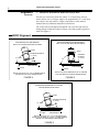
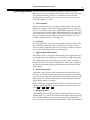
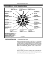
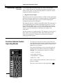
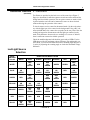
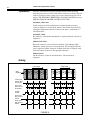
Allen-Bradley User’s Manual PHOTOSWITCH 42CRC Color Registration Control (Cat. No. 42CRC-4000, 4001) Table of Contents Title Page Description . . . . . . . . . . . . . . . . . . . . . . . . . . . . . . . . . . . . . . . . . . . . 1,2 Installation a. Lens Location . . . . . . . . . . . . . . . . . . . . . . . . . . . . . . . . . . . . . b. Mounting . . . . . . . . . . . . . . . . . . . . . . . . . . . . . . . . . . . . . . . . . c. Wiring . . . . . . . . . . . . . . . . . . . . . . . . . . . . . . . . . . . . . . . . . . . 2 2 3 Alignment a. Opaque Web Material . . . . . . . . . . . . . . . . . . . . . . . . . . . . . . . b. Opaque Non-Reflective Web Material . . . . . . . . . . . . . . . . . . . c. Transparent Web Material with Dark Opaque Mark . . . . . . . . . . . . . . . . . . . . . . . . . . . . . 3 3 4 Operating Modes a. Latch . . . . . . . . . . . . . . . . . . . . . . . . . . . . . . . . . . . . . . . . . . . . b. Non-Latch . . . . . . . . . . . . . . . . . . . . . . . . . . . . . . . . . . . . . . . . c. Light or Dark Mark Sensing . . . . . . . . . . . . . . . . . . . . . . . . . . d. Automatic Operation . . . . . . . . . . . . . . . . . . . . . . . . . . . . . . . . e. Manual Operation . . . . . . . . . . . . . . . . . . . . . . . . . . . . . . . . . . f. Red and Green Light Sources . . . . . . . . . . . . . . . . . . . . . . . . . 5 5 5 5 5 6 Additional Features a. Output Dwell . . . . . . . . . . . . . . . . . . . . . . . . . . . . . . . . . . . . . . b. Gated Operation . . . . . . . . . . . . . . . . . . . . . . . . . . . . . . . . . . . . c. Diagnostic Alarm Output . . . . . . . . . . . . . . . . . . . . . . . . . . . . . d. Contrast Check . . . . . . . . . . . . . . . . . . . . . . . . . . . . . . . . . . . . . 7 7 8 9 Operation . . . . . . . . . . . . . . . . . . . . . . . . . . . . . . . . . . . . . . . . . . . . . 10 Maintenance . . . . . . . . . . . . . . . . . . . . . . . . . . . . . . . . . . . . . . . . . . . 11 Specifications . . . . . . . . . . . . . . . . . . . . . . . . . . . . . . . . . . . . . . . . . . 11 a. Outline Dimensions . . . . . . . . . . . . . . . . . . . . . . . . . . . . . . . . . 13 b. Internal Schematic . . . . . . . . . . . . . . . . . . . . . . . . . . . . . . . . . . 13 c. Diagnostic Resistor Selection . . . . . . . . . . . . . . . . . . . . . . . . . 14 d. Cable Color Coding . . . . . . . . . . . . . . . . . . . . . . . . . . . . . . . . . 14 e. Wiring Diagrams . . . . . . . . . . . . . . . . . . . . . . . . . . . . . . . . . . . 15, 16 f. Performance Curves . . . . . . . . . . . . . . . . . . . . . . . . . . . . . . . . . 17 Publication PA-8853 — February 1994 42CRC Color Registration Control Description The Photoswitch Type 42CRC Series 4000 LED Color Registration Mark Control with Automatic Gain Control (AGC) is a fixed focus diffuse-reflective scanning device designed to detect pre-printed registration marks against contrasting backgrounds. Detection of the marks is achieved by sensing the difference in the gray-scale response to the mark and background. This device has two sources of emitted light, a red and a green LED that are selected by an operating-mode switch. The choice of a red or green LED broadens the control’s capability of detecting a wide range of mark and background colors. A small light spot is projected on the material being scanned. The reflectivity of the material at the spot defines the level of the received signal. Changes in the reflectivity, due to the contrast between the printed mark and the background is recognized by the control, which provides an output. This output can then be used by the packaging machine to properly cut, seal, crimp, or fold packages or tubes. The 42CRC Series 4000 also has a number of unique features that enhance flexibility and reliability. S An automatic gain sensitivity control permits fully automatic operation eliminating the need for constant operator interface when mark to background colors change. S A manual sensitivity selection mode enables the operator to fine tune the control to detect poor quality marks. S A built-in diagnostic system provides early-warning alarm indication of gradual loss of operating margin due to changes in contrast, misalignment, or dust prior to loss of output signal, avoiding unexpected process disruption. S Custom microcircuitry for very high sensitivity and increased intelligence in a small workable package. S Fast 250 microsecond response time. S Latch or automatic reset functions. S Adjustable output dwell time. S Selectable light or dark mark detection. S Continuous output short circuit protection. S Reverse polarity protection. 1 42CRC Color Registration Control 2 Description (Continued) S An external gate input makes it possible to blind the control during portions of the machine cycle, eliminating the possibility of false signals between registration marks. S Analog test points allow evaluation of mark contrast prior to running a machine, and three LED status indicators provide setup ease and accuracy. S Quick Disconnect design for ease of installation, reduced downtime and replacement cost. S NPN or PNP outputs. Model 4000 has one NPN (sinking) output rated 100mA at 30 VDC. Model 4001 has one PNP (sourcing) output rated 100 mA at 30 VDC. Both models have a separate diagnostic NPN (sinking) output rated 30 mA at 30 VDC. S Rugged high impact housing is constructed of #380.0 cast aluminum, anodized and epoxy coated for maximum corrosion resistance. S Entire control is rated for NEMA 3, 4, 6P, 12 and 13, IP67 (IEC 529). Installation a. Lens Location For increased flexibility the lens of the 42CRC is interchangeable with the lens cap. Determine which lens location is best for your particular application, taking into consideration the accessibility to the control adjustments and the visibility of the indication lights. When the lens location has been determined, make sure to tighten the lens and cap to effectively maintain a watertight rating. b. Mounting The control must be mounted on a firm stable surface or support. A mounting which is subject to excessive vibration or shifting may cause unreliable operation. This control is designed to detect a mark at a fixed distance from the lens. Mount the control .5 inches (13 mm) from the web to the center of the face of the lens, with the light spot centered on the mark. Web flutter must be held to a minimum to maintain the sensing distance within the +/-- .08 (2 mm) depth of field. To ensure reliable operation, mount the control where the web material travels smoothly over a plate or roller with little flutter and where there are no web creases or wrinkles. See Page 3, Figure 1. 42CRC Color Registration Control 3 42CRC Mounting 42CRC WEB MATERIAL MOUNT THE 42CRC OVER A PLATE OR ROLL TO PREVENT FALSE SIGNALS DUE TO WEB FLUTTER FIGURE 1 Installation c. Wiring (Continued) For proper wiring the 42CRC requires a Photoswitch Cable Assembly #60-2292 ordered separately. The control operates on 10-30 VDC @ 70 mA max. See pages 11 and 12 for complete specifications. All external wiring should conform to the National Electric Codes and applicable local Codes. See wiring diagrams beginning on page 15 for external connections. Alignment The 42CRC is designed to perform reliably on many different types of web material. However, once the device is mounted and wired, it should be aligned to the particular web material for optimum performance and reliability. Most marks can be detected by using the following mounting and alignment methods. Difficult mark colors and some foil material may require the use of the Test Points on the control to determine the best position for maximum mark to background contrast (see Page 9, d., Contrast Check). a. Opaque Reflective Web Material For sensing light or dark registration marks on opaque reflective surfaces, mount the control .5 (13 mm) above the surface of the material. If the surface is shiny or reflective, angle the control about 10 to 15 degrees to the perpendicular (75 to 80 from the control to the web surface). See Figure 2, Page 4. b. Opaque Non-Reflective Web Material For sensing light or dark registration marks on material with non-reflective surfaces, mount the control .5 (13 mm) from the surface and perpendicular (90) to the web. See Figure 3, Page 4. 42CRC Color Registration Control 4 Alignment c. Transparent Web Material With Dark Opaque Mark (Continued) For this type of material, mount the control .5 (13 mm) above the web surface and at a 10 to 15 degree angle to the perpendicular (75 to 80 from the control to the web surface). A light colored plate or roller must be mounted directly behind the transparent web material. The control will see through the transparent web, sense the light colored background providing the required contrast to the dark opaque registration mark. See Figure 4. 42CRC Alignment OPAQUE NON-REFLECTIVE WEB MATERIAL WITH LIGHT OR DARK REGISTRATION MARKS OPAQUE REFLECTIVE WEB MATERIAL WITH LIGHT OR DARK REGISTRATION MARKS 42CRC 42CRC SCANNING DISTANCE .5 (13mm) 75 TO 80 SCANNING DISTANCE .5 (13mm) 90 WEB MATERIAL WEB MATERIAL PLATE PLATE MOUNT THE 42CRC PERPENDICULAR TO THE WEB FOR NON-REFLECTIVE (MATTE) WEB SURFACES MOUNT THE 42CRC AT A 10 TO 15 DEGREE ANGLE FOR REFLECTIVE (SHINY) WEB SURFACES. FIGURE 2 FIGURE 3 TRANSPARENT WEB MATERIAL WITH DARK OPAQUE REGISTRATION MARKS 42CRC SCANNING DISTANCE .5 (13mm) 75 TO 80 PLATE TRANSPARENT WEB MATERIAL MOUNT THE 42CRC AT A 10 TO 15 DEGREE ANGLE. MOUNT A PLATE MADE OF A LIGHT COLORED MATERIAL BEHIND THE TRANSPARENT WEB MATERIAL. FIGURE 4 42CRC Color Registration Control Operating Modes 5 After the control has been installed and aligned, it must be set for the particular operation. An important feature of the control is that it gives the user complete flexibility to select any combination of the four major operating modes listed below via a convenient external function selector switch. See Figures 5, 6, and 7. a. Latch Operation This function allows the user to latch the switched output “ON” for an indefinite period when a mark is detected. The output is reset by applying a positive 4 to 30 VDC to the “white” GATE/RESET input lead or by simply switching this lead to the B+ supply. Electromechanical or solid state contacts can be used to reset the control. This function enables the output duration to be extended, and the output reset later in the machine cycle. The “Latch” switch positions are “A” through “D”. b. Non-Latch In the non-latch mode, detection of a mark turns the switched output “ON” for an adjustable dwell time of up to 250 milliseconds. After the dwell time, the output will automatically reset. This mode is similar to an adjustable one-shot. Non-latch positions are “E through H”. c. Light and Dark Mark Sensing The 42CRC can be set to energize on the leading edge of light marks on a dark background or the leading edge of dark marks on a light background. The alphabetic positions on the function switch have letters with white backgrounds and letters with black backgrounds. Select white background positions for light mark sensing and black background positions for dark mark sensing. d. Automatic Operation “Automatic” mode provides stable, adjustment-free sensing for most applications. The 42CRC automatically adjusts the sensitivity, compensating for variations in background colors and lens contamination. It also provides additional gain for the low contrast marks on dark backgrounds and scanning of glossy surfaces at an angle. In this position the orange LED marked “AUTO” is “ON” and the manual sensitivity adjustment is NOT functional. Switch positions for this mode are A, A , C, C , E, E , G, G . e. Manual Operation This operating mode extends the control’s sensing capability for very low contrast marks (e.g., pastel colors) on light backgrounds. Signal processing in the 42CRC continually corrects for variations in background signal level. The result is a mark detection system that has a more stable threshold 42CRC Color Registration Control 6 Operating Mode (Continued) level, and is easier to set up in the manual operation mode. The control must be set in the manual mode when the “test points” are used to check for sufficient sensing contrast (see “Contrast Check” on page 9.) In this position the orange LED marked “AUTO” will be “OFF” and the manual sensitivity adjustment is functional. Switch positions for this mode are B, B , D, D , F, F , H, H . f. Red or Green Light Sources The 42CRC Control has both a red and a green LED light source. The function switch permits selection of one or the other LED. The LED selection guide, Figure 8 on page 9, lists which LED to use with some basic mark and background color combinations. To select the proper light source for colors not listed in Figure 8, make a Contrast Check as described on page 13. Test the mark/background with each LED and select the one that provides the maximum mark to background voltage change. The red LED corresponds with switch positions A, A , B, F . The Green LED corresponds with switch positions C, G , and H, H . INTERCHANGE LENS AND CAP TO CHANGE SENSING DIRECTION AUTOMATIC/MANUAL INDICATOR ORANGE LED “ON” IN AUTOMATIC MODE MARGIN INDICATOR GREEN LED “ON” WHEN OPERATING MARGIN IS AT LEAST 2 TO 1 OUTPUT INDICATOR RED LED “ON” WHEN THE CONTROL OUTPUT IS “ON” B C , E, , D, E D , and F, , G, PHOTOSWITCH COLOR REGISTRATION CONTROL 42CRC--4000 AUTO SUPPLY OUTPUT ALARM SCANNING MARGIN 4D 30vDC 70MA MAX 100MA 30VDC MAX N.O. NPN 51NK 20MA 30VDC MAX WHITE- GATE (- ) / RESET (+) ORANGE- DIAG. ALARM SIGNAL BLACK- NEGATIVE RED- POSITIVE BLUE- OUTPUT TEST POINTS TEST POINTS TO CHECK MARK CONTRAST QUICK-DISCONNECT Cable Assembly OUTPUT DWELL TIME ADJUSTMENT (NON-LATCH MODE) 6 7 5 4 3 SENSITIVITY ADJUSTMENT (MANUAL MODE) FIGURE 5 2 1 MODE 8 H A A 1 B 0 9 H B G C G C F D F 0 E E D 9 SENS 2 3 4 5 6 8 7 DWELL FUNCTION SELECTOR SWITCH 42CRC Color Registration Control 7 Function Selector Switch Operating Modes NON-LATCHED OUTPUT DARK MARK MANUAL SENSITIVITY GREEN LED LATCHED OUTPUT LIGHT MARK AUTOMATIC SENSITIVITY RED LED LATCHED OUTPUT DARK MARK AUTOMATIC SENSITIVITY RED LED LATCHED OUTPUT LIGHT MARK MANUAL SENSITIVITY RED LED NON-LATCHED OUTPUT LIGHT MARK MANUAL SENSITIVITY GREEN LED NON-LATCHED OUTPUT DARK MARK AUTOMATIC SENSITIVITY GREEN LED H G G F F NON-LATCHED OUTPUT LIGHT MARK AUTOMATIC SENSITIVITY GREEN LED NON-LATCHED OUTPUT LIGHT MARK MANUAL SENSITIVITY RED LED HAA EED B B C C D NON-LATCHED OUTPUT DARK MARK AUTOMATIC SENSITIVITY RED LED Additional Features LATCHED OUTPUT LIGHT MARK AUTOMATIC SENSITIVITY GREEN LED LATCHED OUTPUT DARK MARK AUTOMATIC SENSITIVITY GREEN LED LATCHED OUTPUT LIGHT MARK MANUAL SENSITIVITY GREEN LED NON-LATCHED OUTPUT LIGHT MARK MANUAL SENSITIVITY RED LED NOTE: ALL WHITE LETTERS ON BLACK BACKGROUNDS INDICATE THE DARK ENERGIZE (MARK) POSITION. ALL BLACK LETTERS ON WHITE BACKGROUNDS INDICATE THE LIGHT ENERGIZE (MARK) POSITION. LATCHED OUTPUT DARK MARK MANUAL SENSITIVITY RED LED NON-LATCHED OUTPUT LIGHT MARK AUTOMATIC SENSITIVITY RED LED LATCHED OUTPUT DARK MARK MANUAL SENSITIVITY GREEN LED FIGURE 6 a. Output Dwell Time Control The Dwell Control (Figure 6) extends the “ON” time of the control output to a definable time limit. Typical applications would be controlling an operation that requires a well-defined time period (e.g., a pause for a product filling, cutting, or sealing operation). The output dwell time is linearly adjustable up to 250 milliseconds. The longer “In” time of either the mark presence or dwell control setting defines the “On” duration of the control output. b. Gated Operation Gating or “blinding” the control is possible by simply switching the white Gate/Reset lead to ground. It is desirable that the scanning area is free of any printing except the registration marks. If other markings are in the scan area, the control will detect them as registration marks. 42CRC Color Registration Control 8 Additional Features (Continued) To avoid detecting the unwanted marks, the control can be disabled “gated” during the times the unwanted marks appear (see Figure 9). The control can be “gated” by using electromechanical or solid state contacts synchronized with the machine cycle. c. Diagnostic Alarm Output This feature provides for advanced remote (via CRT or control panel alarm indication) warning of gradual loss of signal strength due to misalignment, dust or drift in mark contrast prior to loss of a control output signal, avoiding unexpected process disruption. The diagnostic alarm is a normally closed NPN output. This output goes to the open (indicating) state when the signal margin drops below 1.5.X for seven consecutive marks (this is to avoid a false alarm) of any period or duration. The diagnostic output also goes to the indicating state when the cable is severed or disconnected or when the power supply to the control fails. The first occurrence of a signal margin 1.7X, indicative of correction of a fault condition resets the diagnostic alarm. Since the diagnostic alarm feature is not time-based, its operation is not affected by operations employing indefinite pauses. Function Selector Switch Operating Modes The selection chart makes it easy to select the proper operation mode on the function switch shown in Figure 6. Example: The operating mode required is as follows: PHOTOSWITCH 1. Output — Non-Latch COLOR REGISTRATION CONTROL 2. Spot (LED) Color-Green 3. Operating Mode — Automatic DARK MARK LIGHT MANUAL AUTO MODE RED SPOT GREEN LATCH NON-LA. SWITCH POSITION 42CRC-4000 OUT Two function switch selection charts are provided with each registration control, one is attached to the control, the other chart with adhesive backing can be mounted on the machine for easy reference. A A B B C C D D E E F F G G H H 4. Mark Color — Dark Select a switch position which has a white dot in each of the above columns. The correct switch position for this application is 55-5080A FIGURE 7 G . 42CRC Color Registration Control Additional Features 9 d. Contrast Check (Continued) Test Points are provided on the back cover of the control (see Figure 5, Page 6) to determine if sufficient contrast exists between the mark and the background for reliable operation. The test point contacts are made of nickel plated stainless steel and can be immersed in water or short circuited without affecting the operation of the control. To check contrast, set the control in the manual mode. Set the web stationary with the light spot of the control on the background. Using a DC voltmeter (100K ohm/volt), connect the test probes to the test points. Note the reading and repeat the measurement with the light spot centered on the mark. If the difference between the two readings is in excess of 300 mV, there is sufficient contrast for reliable operation. Check the mark/background with both the green and red LEDs. Use the LED that provides the maximum voltage difference. By making this contrast check, you can also determine the correct mounting angle (Figures 2, 3, and 4) by adjusting the scanning angle to obtain the maximum voltage difference. Led Light Source Selection BACKGROUND COLOR REGISTRATION MARK COLOR WHITE WHITE BLUE GREEN YELLOW ORANGE RED BLACK RED OR GREEN RED RED OR GREEN GREEN GREEN RED OR GREEN RED OR GREEN RED OR GREEN RED OR GREEN RED RED OR GREEN RED OR GREEN RED OR GREEN RED GREEN RED OR GREEN GREEN GREEN GREEN RED BLUE RED OR GREEN GREEN RED RED OR GREEN YELLOW RED OR GREEN RED OR GREEN RED OR GREEN ORANGE GREEN RED OR GREEN RED OR GREEN RED OR GREEN RED GREEN RED RED GREEN GREEN BLACK RED OR GREEN RED OR GREEN GREEN GREEN RED FIGURE 8 RED RED 42CRC Color Registration Control 10 Operation After the control has been properly installed and the chosen operating mode has been selected, set the dwell and the sensitivity controls to the full counter-clockwise position. Apply power to the control and set the web in motion. THE WEB MUST BE MOVING AT LEAST 2 INCHES (51 mm) PER SECOND FOR PROPER CONTROL FUNCTION. Automatic, Non-Latch In this setting no sensitivity adjustment is required and the sensitivity control is inoperative. Set the dwell control to the desired output dwell by rotating the adjustment clockwise to increase the time to a maximum of 250 milliseconds. Automatic, Latch No sensitivity or dwell time adjustments are required and both controls are inoperative. Manual, Non-Latch Rotate the sensitivity control clockwise until the “Green Margin Light” illuminates with the presence of a moving mark. This setting provides the correct signal for reliable operation. If output dwell time is required, rotate the dwell control clockwise to the appropriate duration. Manual, Latch Set the sensitivity control as described above. The dwell time is inoperative. Gating DARK MARK LIGHT MARK WEB MATERIAL X Y 42CRC-4000 NPN OUTPUT NO-GATING 42CRC-4001 PNP OUTPUT NO-GATING GATING SIGNAL 42CRC-4001 NPN OUTPUT GATED 42CRC-4001 PNP OUTPUT GATED FIGURE 9 X Y X Y 42CRC Color Registration Control Maintenance Specifications Clean the lens surface periodically. With a non-abrasive cleaning solution (mild soap) and a soft cloth. Do not use strong chemicals on the plastic lens. 11 12 42CRC Color Registration Control Voltage Supply: . . . . . . . . . . . . . . . . . . . . . . . . . . . . . . . . . 10V to 30VDC Current Consumption . . . . . . . . . . . . . . . . . . . . . . . . . . . . . . . 70mA Max. Output: Model 4000 . . . . . . . . . . . . . . . . . . . . . . . . . . . . . . Open Collector NPN (Current Sink) Model 4001 . . . . . . . . . . . . . . . . . . . . . . . . . . . . . . Open Collector PNP (Current Source) Output Rated Load Current (On-State) . . . . . . . . . . . . . . . . . . . . . 100mA Output Rated Load Voltage (Off-State) . . . . . . . . . . . . . . . . . . . . . 30VDC Output Short Circuit Protection . . . . . . . . . . . . . . . . . . . . . . . . Continuous Response Time at Maximum Contrast (Black & White) . . . . . . . . . . . . . . . . . . . . . . . . . . . . 250 Microseconds Minimum Web Velocity . . . . . . . . . . . . . . . . . . . . . . . . . . 2 Inches per sec. (51mm per second) Maximum Output Dwell . . . . . . . . . . . . . . . . . . . . 250 Milliseconds min. Minimum Output Dwell (Overridden by Signal Duration) . . . . . . . . . . . . . . . 250 Microseconds Transmitter LED’s (Selectable Red or Green) . . . . . . . . . . . . . . . . . . . Visible Red, 630 nm Visible Green, 570 nm Minimum Useable Mark to Background Voltage Change (Measured at Test Points in Manual Mode) Manual Mode . . . . . . . . . . . . . . . . . . . . . . . . . . . . . 250 Millivolts D.C. Automatic Mode . . . . . . . . . . . . . . . . . . . . . . . . . . . 500 Millivolts D.C. Scanning Distance . . . . . . . . . . . . . . . . . . . . . . . . . . . . . . . . . 0.5 (13mm) Depth of Field . . . . . . . . . . . . . . . . . . . . . . . . . . . . . . . . . +/-- .08 (2mm) Min. Size of Mark at Scanning Distance . . . . . . . . . . . . . . . . 0.08 X .10 (2mm X 2.5mm) False Pulse Suppression . . . . . . . . . . . . . . . . . . . . . . . . . . . . . . . . . . . . Yes Reverse Polarity Protection . . . . . . . . . . . . . . . . . . . . . . . . . . . . . . . . . Yes External Gating Mode . . . . . . . . . . . . . . . . . . . . . . . . . . . . . . . . . . . . . Yes Latching Output Mode with External Reset . . . . . . . . . . . . . . . . . . . . Yes Diagnostic Alarm . . . . . . . . . . . . Following seven successive marks below margin of 1.5 X, or loss of power. Diagnostic Alarm Output . . . . . . N.C. Open collector NPN output, 30mA max., 30VDC max. Operating Environment . . . . . . . Housing made of #380.0 cast aluminum Anodized and epoxy coated for corrosion resistance. Rated for NEMA 3, 4, 6P, 12, and 13. IP67 (IEC 529) Test Points for Contrast Check . . . . . . . . . . . . . . . . . . . . . . . . . . . . . . Yes 42CRC Color Registration Control Specifications (Continued) 13 Dimensions . . . . . . . . . . . . . . . . . . . . . . . . 3.80 L X 2.95 H X 1.31 D (97mm L X 75mm H X 33mm D) Weight . . . . . . . . . . . . . . . . . . . . . . . . . . . . . . . . . . . . . . . . . 12 oz (350 g) Storage Temperature . . . . . . . . . . . . . . . . --13F (--25C) to 167F (75C) Operating Ambient Temp. Range . . . . . . . . . 32F (0C) to 158F (70C) Max Relative Humidity . . . . . . . . . . . . . . . . . . . . . . . . . . . . . . . . . . . 95% Cable Assembly #60-2292 (Order Separately) . . . . . . . . 10 Feet (3m) 5 conductor with shield, #22 AWG (26 X 36) Stranded. Flexible mount PVC jacket 260 nominal O.D. rated UL 2661 — 150C 300 volts. 5 pin (female) watertight connector. Agency Approvals . . . . . . . . . . . . . . . . . . . . . . . UL listed, CSA certified 42CRC Color Registration Control 14 Outline Dimensions (mm between brackets) 2.500 (63.50) Using Optional Lens Position 1.312 (33.32) .656 (16.62) .419 (10.64) Focal Points (Scanning Distance) .470 (11.94) PHOTOSWITCH .375 (9.53) COLOR REGISTRATION CONTROL 42CRC--4000 SUPPLY OUTPUT 2.357 (59.87) 1.10 (27.94) 3.375 (85.73) .432 (10.97) 1.875 (47.63) 4D 30vDC 70MA MAX 100MA 30VDC MAX N.O. NPN 51NK 20MA 30VDC MAX ALARM SCANNING WHITE- GATE (- ) / RESET (+) ORANGE- DIAG. ALARM BLACK- NEGATIVE RED- POSITIVE BLUE- OUTPUT .415 1.10 (10.54) (27.94) .830 (21.08) 1.930 (49.02) M5 X 0.8 Thread .250 (6.35) Max. thread depth 2 places 1.437 (36.50) M5 X 0.8 Thread .250 (6.35) Max. thread depth 4 places 2.955 (75.06) 2.800 (71.12) #60-2292 Cable Assembly 5 6 7 4 3 2 1 MODE 8 HA A 1 B 0 9 H B G C G C F D F 0 E E D 9 SENS FIGURE 10 2 3 4 5 6 8 7 DWELL Internal Schematic Photo Detector Board Microcircuit Pulse Amp Margin Comp. Manual Sensitivity Adjustment Integrator and Analog Amplifier (+) Margin Indicator Green LED Indicator Red LED Signal Comp. Output NPN or PNP Optics Overload Protection LED’S Auto Mode Indicator Orange LED Pulse Generator Red Green (--) Dwell Time Gate/Reset Diagnostic Alarm Operating Mode Logic FIGURE 11 Diagnostic Output NPN 42CRC Color Registration Control 15 Diagnostic Alarm Minimum Resistor Value Selection 1000 MINIMUM RESISTANCE (OHMS) 833 667 500 333 0 (USE 1/2 WATT RESISTOR) 10 15 20 VOLTAGE (D.C.) 25 30 FIGURE 12 Color Coding #60-2292 Cable Assembly WHITE-GATE (--) / RESET (+) ORANGE-DIAG. ALARM BLACK-NEGATIVE (--) RED-POSITIVE (+) BLUE-OUTPUT FIGURE 13 42CRC Color Registration Control 16 Wiring Diagrams NPN OUTPUT 42CRC -- 4000 Latched Output -- Function Switch Positions “A” Through “D” with or without External Gating External Connections 42CRC-4000 Cable Assembly #60-2292 Connector Red (+) (+) Supply 10-30VDC Load Blue--NPN Output Reset* Switch (close to unlatch) Control Output (NPN) Sink 30mA max, remote diagnostic indicator by customer (if used) Orange-NPN Diagnostic Alarm Diagnostic Output (NPN) Sink Resistor by customer (if remote diagnostic indicator is used.) See Figure 12 for resistor selection. White-Gate (--)/Reset (+) Black (--) (--) Supply Bare-Shield Gating Switch close to inhibit (if used) NPN will sink 0.3 mA *WARNING DO NOT CLOSE THE RESET AND GATING SWITCHES SIMULTANEOUSLY FIGURE 14 NPN OUTPUT 42CRC -- 4000 Non-Latched Output -- Function Switch Positions “E” Through “H” with or without External Gating External Connections 42CRC-4000 Cable Assembly #60-2292 Connector Red (+) (+) Supply 10-30VDC Load Blue-NPN Output Control Output (NPN) Sink Diagnostic Output (NPN) Sink Orange-NPN Diagnostic Alarm White-Gate (--)/Reset (+) Resistor by customer (if remote diagnostic indicator is used.) See Figure 12 for resistor selection. 30mA max, remote diagnostic indicator by customer (if used) Black (--) (--) Supply Bare-Shield Gating Switch l t i hibit 42CRC Color Registration Control 17 Wiring Diagrams (Continued) PNP OUTPUT 42CRC -- 4001 Latched Output -- Function Switch Positions “A” Through “D” with or without External Gating External Connections 42CRC-4001 Reset* Switch (close to unlatch) Cable Assembly #60-2292 Connector Red (+) Control Output (PNP) Source (+) Supply 10-30VDC Resistor by customer (if remote diagnostic indicator is used.) See Figure 12 for resistor selection. Blue-PNP Output Load 30mA max, remote diagnostic indicator by customer (if used) Orange-NPN Diagnostic Output White-Gate (--)/Reset (+) Diagnostic Output (NPN) Sink Black (--) (--) Supply Bare-Shield *WARNING DO NOT CLOSE THE RESET AND GATING SWITCHES SIMULTANEOUSLY FIGURE 16 *Gating Switch close to inhibit (if used) NPN will sink 0.3mA PNP OUTPUT 42CRC -- 4001 Non-Latched Output -- Function Switch Positions “E” Through “H” with or without External Gating External Connections 42CRC-4001 Cable Assembly #60-2292 Connector Red (+) Control Output (PNP) Source (+) Supply 10-30VDC Blue-PNP Output Load Orange-NPN Diagnostic Output Diagnostic Output (NPN) Sink White-Gate (--)/Reset (+) Resistor by customer (if remote diagnostic indicator is used.) See Figure 12 for resistor selection. 30mA max, remote diagnostic indicator by customer (if used) Black (--) (--) Supply Bare-Shield Gating Switch close to inhibit 42CRC Color Registration Control 18 Performance Curves Relative Sensitivity Vs Web Speed (Automatic Mode) 1.1 Relative Sensitivity 1 .6 .4 .2 2 7 10 70 100 700 1000 Speed (In/Sec.) (Metric Conversion 1 = 25.4mm) FIGURE 18 Relative Sensitivity Vs Web Speed (Manual Mode) 1.1 Relative Sensitivity 1 .8 .6 .4 .2 .5 .7 1 5 10 70 100 Speed (In/Sec.) (Metric Conversion 1 = 25.4mm) FIGURE 19 700 1000 GuardShield™ Safety Light Curtain User Manual 40 Original instructions R GuardShield™ Safety Light Curtain User Manual 40 Original instructions R GuardShield™ Safety Light Curtain User Manual 40 Original instructions R PHOTOSWITCH is a registered trademark of Rockwell Automation. www.rockwellautomation.com Power, Control and Information Solutions Headquarters Americas: Rockwell Automation, 1201 South Second Street, Milwaukee, WI 53204-2496 USA, Tel: (1) 414.382.2000, Fax: (1) 414.382.4444 Europe/Middle East/Africa: Rockwell Automation NV, Pegasus Park, De Kleetlaan 12a, 1831 Diegem, Belgium, Tel: (32) 2 663 0600, Fax (32) 2 663 0640 Asia Pacific: Rockwell Automation, Level 14, Core F, Cyberport 3, 100 Cyberport Road, Hong Kong, Tel: )852) 2887 4788, Fax: (852) 2508 1846 Publication PA--8853 February 1994 Supersedes Publication PA--8853 February 1989 Copyright 1994 Rockwell Automation. Printed in USA