1
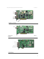
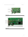
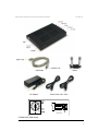
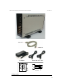
TVB370/380/390/590(E,S)/593/
594/595/597A/591S/598/599A
DVB-T/H/T2, ATSC-8VSB/MH,
DVB-C (J.83/A, C), J.83/B,
DVB-S/S2, ISDB-T/S, TDMB,
DTMB, CMMB, DVB-C2, I/Q PLAY
USER MANUAL
www.teleview.com
http://www.teleview.com
TVB370/380/390/590(E,S)/593/594/595/597A/591S/598/599A
User Manual
Table of Contents
1. OVERVIEW
3
2. PACKAGE CONTENTS
3
3. REQUIREMENTS
9
4. HARDWARE INSTALLATION
9
5. SOFTWARE INSTALLATION
10
6. OPERATING
14
7. CHANGES FROM TPG0590 TO TPG0590VC
40
7.1. Supports DVB-T2 Multi-PLP.
40
7.2. Supports TVB597A Ver.2.
40
7.3. No need to restart application after being inputted authorization key.
40
7.4. Disabled changing some control buttons while playing or recording.
40
7.5. DAC I/Q Offset
41
7.6. Pause is supported while playing a file.
45
7.7 How to use TVB594.
46
7.8 Multi-Board IP Streaming is supported.(refer to page29)
46
7.9 SET Satellite/LNB Frequency.
47
7.10 Default Pid assignment for ISDB-T 13seg.
48
7.11 Amplitude Equalizer
49
7.12 New modulator types
50
7.13 Single Tone.
51
7.14 DVB-T2/C2 DVB-ASI Direct Modulation.
51
7.15 RF Amplitude control.
52
7.16 PCR RESTAMPING.
52
7.17 T2MI File Generation.
53
7.18 TS I/O Mode.
53
7.19 TS Output control.
54
7.20 Configuration Group Play
54
7.21 DVB-S2 Multiple Input Stream (MIS)
57
2
TVB370/380/390/590(E,S)/593/594/595/597A/591S/598/599A
User Manual
1. OVERVIEW
This user guide contains the information you need when installing and controlling the TVB###
board.
2. PACKAGE CONTENTS
Check your PCI board package for the following items.
Items
PCI(USB) Board
Bracket Assembly
Installation USB
User Manual
USB Cable,
AC Power (110/220V)Code,
19V DC Adapter
Quantity
TVB370,TVB380,TVB390,TVB590(E,S),
TVB593,TVB594,TVB591S,TVB595(USB),
TVB597A(USB),TVB598,TVB599A(USB)
BNC to BNC connector +
BNC to SMB cable(TVB390v3.0,v3.1)
1
1
1
1
TVB595(USB), TVB597A(USB),TVB599A(USB)
1/1/1
(TVB380 V3.0, V3.1 PCI Board)
(Bracket Assembly)
3
TVB370/380/390/590(E,S)/593/594/595/597A/591S/598/599A
User Manual
(TVB590E Board for PCI Express)
(TVB590 Board)
(TVB590S Board)
4
TVB370/380/390/590(E,S)/593/594/595/597A/591S/598/599A
User Manual
(TVB390 V6, V7 Board)
(TVB370 PCI Board). Caution: In case of IF-only version, RF OUTPUT is replaced with IF
OUTPUT.
(TVB593 Board)
5
TVB370/380/390/590(E,S)/593/594/595/597A/591S/598/599A
User Manual
(TVB591S Board)
RF OUT
TS OUT
TS IN
(TVB598 Board)
6
TVB370/380/390/590(E,S)/593/594/595/597A/591S/598/599A
User Manual
USB Cable
DC Adaptor
Stand
Power Cable 110v / 220v
MATE PLUG
(TVB595/597A USB Board)
7
TVB370/380/390/590(E,S)/593/594/595/597A/591S/598/599A
User Manual
USB Cable
DC Adaptor
Power Cable 110v / 220v
MATE PLUG
(TVB599A USB)
8
TVB370/380/390/590(E,S)/593/594/595/597A/591S/598/599A
User Manual
3. REQUIREMENTS
- Pentium PC with Microsoft Windows XP(Service Pack 2 or higher), 2000 Professional(Service
Pack 2 or higher), Vista(32/64bits) or Windows 7(32/64bits) installed
- Card and cables
- USB2.0 or higher for TVB595/TVB597A.
Specially, to use TVB595/TVB597A USB board normally, high performance host PC required –
Pentium IV 3GHz and 1GB RAM or above recommended.
This specification can be changed as modulation parameters and options.
- Installation USB (Available on ftp://ftp.teleview.com/TVB590_5_7_Windows/)
- If TPG0590(vX.X.X)_VC package, you need the following prerequisites
1. Windows Installer 3.0 or later in your system.
2. Dot NET Framework 2.0 or later in your system.
4. HARDWARE INSTALLATION
1. Before installing, touch the grounded part of PC to protect the board from
static electricity.
2. Turn off the computer.
3. Remove the power cord from the PC.
4. Open the case
5. Assemble bracket and cables
6. Connect Bracket Assembly to PCI Board (only TVB390v3.0, v3.1).
7. Insert a board into any available PCI slots
8. Place screws to the brackets to secure the PCI board to the case.
9. Cover the case and Turn on the computer
* To install TVB595/TVB597A/TVB599A USB board, prepare a USB cable (series A/B typed).
Then, connect series B type connector to TVB595 device and series A type connector to the PC. If
it is the first connection, “new device driver found” message will be shown and follow the Windows
device installation procedure like as TVB590 board.
* To use TVB597A board with other TVB595/USB board, Re-install the newest device driver
included in the package.
* To use TVB590S board with other TVB590/PCI board, Re-install the newest device driver
included in the package.
CAUTION - TO REDUCE THE RISK OF ELECTRIC SHOCK, GROUNDINGS
BETWEEN PC AND DUT SHOULD BE TIED AT ONE POINT. IF NOT, IT
MAKES SOME WRONG OPERATON OF PCI AND USB BOARDS.
(DUT: DEVICE UNDER TEST)
9
TVB370/380/390/590(E,S)/593/594/595/597A/591S/598/599A
User Manual
5. SOFTWARE INSTALLATION
1.
Run Setup.exe(D:\TVB370\380\390\590\593\595\Install\Setup.exe)
If Dot NetFramework 2.0 or later is installed, go to step 2,
Step 1.Click Install button to continue.
Step 2. Click Next button to continue.
10
TVB370/380/390/590(E,S)/593/594/595/597A/591S/598/599A
User Manual
2. Click Next button to continue.
3. Click Install button to continue.
11
TVB370/380/390/590(E,S)/593/594/595/597A/591S/598/599A
User Manual
4. Click Finish button.
5.
Install device driver
5.1 Click Next button to continue.
12
TVB370/380/390/590(E,S)/593/594/595/597A/591S/598/599A
User Manual
5.2 Click Install this driver software anyway to continue.
5.3 Click Finish button.
6. Completed installation of application and device driver.
13
TVB370/380/390/590(E,S)/593/594/595/597A/591S/598/599A
User Manual
6. OPERATING
TPG0590.EXE/TPG0590VC.EXE is GUI-based control program. If you want to use consol-based
application, refer to SDK’s HLD/LLD demo source.
TVB370/IF is a board that only IF output is available.
TVB370/8VSB is a board that lower frequency (~79MHz) RF is available.
TVB590 is a board that TS input ports are selectable. It includes the whole function of
TVB390V7.
TVB595/TVB597A is USB typed-board. It includes the whole function of TVB590.
In case of TVB595/TVB597A, please shut down the application before power off.
Or, it may make some damages or wrong operation.
TVB590E is a PCI express-typed board.
TVB590S is a board that only RF output and TS input are available. To use TVB590S
properly, device driver should be re-installed with the newest device driver at the
package.
TVB593 is a PCI express-typed board and supports all functions of TVB590S and
TVB597A. To use TVB593 properly, the device driver should be re-installed with
the newest device driver. If TVB593 is installed, do not run old s/w(v6.12.21 or
lower) with TVB593 board.
14
TVB370/380/390/590(E,S)/593/594/595/597A/591S/598/599A
User Manual
TVB594, a PCI express-typed board, support only VSB modulator and generate up to 3
RF channels. TPG0590VC version 7.5.0 or later can support this board.
How to use TVB594, please refer to item 8.7.
All operation is available with mouse and keyboard operation or TPG430B’s front-panel
keypad.
TVB591S is a board that only RF output and TS input are available. To use TVB590S
properly, the device driver should be re-installed with the newest device driver at
the package. TPG0590VC version 7.5.5 or later can support this board.
TVB598 is a PCI express-typed board and supports all functions of TVB593 and TVB597A. DVBT2 FFT 16K,32K is newly supported. To use TVB598 properly, the device driver should be reinstalled with the newest device driver. If TVB598 is installed, do not run old s/w(v7.8.3 or lower).
TVB599A is a USB typed-board and supports all functions of TVB593 and TVB597A. DVB-T2 FFT
16K,32K is newly supported. To use TVB599A properly, the device driver should be re-installed
with the newest device driver. If TVB599A is installed, do not run old s/w(v7.8.3 or lower).
15
TVB370/380/390/590(E,S)/593/594/595/597A/591S/598/599A
User Manual
Authorization Key CONFIRM
[TVB390V7, TVB370/IF, TVB590(E,S), TVB593, TVB594, TVB591S, TVB595, TVB597A, TVB598,
TVB599A] TPG0590.EXE/TPG0590VC.EXE will confirm the authorization key information.
When the above dialog appears, put valid authorization key. The authorization key will
be accompanied with the install USB or can be found on the backside of the PCI board.
If you do not have any valid authorization key, contact with PCI cards’ provider
and send the modulator types and the serial number, which is logged at
lld_bd_##.LOG file like as
“EncryptedSN : C74C6DA0F2C465BA”. Use an external or on-screen keyboard or
mouse to put authorization key.
To update authorization key information, refer to Authorization key at Advanced.
[TVB590(E,S), TVB593, TVB594, TVB591S, TVB595, TVB597A, TVB598, TVB599A]
If old TVB390 application was installed, copy the “license.dat” file from the TVB390
installation folder to TVB590/TVB595 installation folder before using new TVB590
application.
16
TVB370/380/390/590(E,S)/593/594/595/597A/591S/598/599A
User Manual
PLAYING FILES
- [TS File]
Click
button to select a file.
- [TS List]
Click Add button to add streams to list.(Maximum 20)
Click Delete All button to remove all streams from list.
Click Delete button to remove one stream from list.
Click Loop Play button
.
Click Start Playback button
.
TS stream will be output through RF, DVB-ASI and SMPTE 310M port.
17
TVB370/380/390/590(E,S)/593/594/595/597A/591S/598/599A
User Manual
If the current Playback rate (bps) exceeds the Maximum playback rate (bps)
(+5ppm), the warning dialog will be shown.
18
TVB370/380/390/590(E,S)/593/594/595/597A/591S/598/599A
User Manual
To set Restamping on Loop
In pull-down menu, choose Playback. Click Restamping on Loop....
Then, Restamping on Loop dialog will be shown
- If source is not [TS File], this function is ignored.
TIP: PCR/PTS/DTS may be required in case of A/V DECODING.
19
TVB370/380/390/590(E,S)/593/594/595/597A/591S/598/599A
User Manual
To set Interval Play
In pull-down menu, choose Playback. Click Interval Play....
Then, Interval Play dialog will be shown.
- Use interval play must be checked.
- Play begin / Play finish format must be ##:##:##.
20
TVB370/380/390/590(E,S)/593/594/595/597A/591S/598/599A
User Manual
Output control
To set Frequency Plan
In pull-down menu, choose Configuration, Output. Click RF Frequency Plan....
Then, Frequency Plan dialog will be shown.
- If you want a user-defined frequency plan, select Custom plan at Frequency
plan and click Edit button to define a new frequency plan.
<Channel
Number,
Frequency(HZ)>
paired
information
user_channel_table.txt file.
is
read
from
21
TVB370/380/390/590(E,S)/593/594/595/597A/591S/598/599A
User Manual
You can set IF value as 36 or 44 MHz.
[TVB380V4, TVB380V6, TVB390V7, TVB370/IF] If two more boards are used at the
same time, IF must be selected differently each other.
[TVB380V3] 36.125 MHz is selectable.
[TVB370/8VSB,TVB590S, TVB593, TVB591S, TVB597A (Ver.2 or higher)] IF is not
available. By default, IF menu is disabled.
[TVB390V7, TVB590, TVB595, TVB597A (Ver.1)] In case of ISDB-T, IF is
35.857000MHz or 43.857000MHz.
Caution:[V6.12.19 or higher application] IF output will be shifted as 1~999,999Hz
unit RF value.
To change RF LEVEL,
- Set Atten value as 0~31.5dB or 0~158.5 dB if TAT4710 (external attenuator by
TELEVIEW) is installed.
How to set TAT4710.(Only 1 unit is supported.)
1. Check the product number of the target board.
2. Close the application.
3. Click "Start/Run..." menu and enter "regedit". Click OK button and then
“registry editor" will be opened.
4. Go to HKEY_CURRENT_USER\software\TELEVIEW\TPG0590_##\StartUp\USETAT4710
menu. The ## is product number of TVB59x board.
5. Set value as '1' (another board’s value must be set to ‘0’.)
6. Close "registry editor"
7. Restart the TVB590VC application.
- RF LEVEL can be decreased linearly according to RF frequency increase. So,
check AGC (Auto Gain Control) to keep a constant RF LEVEL. If AGC is
checked, Atten range will be decreased as much as AGC Atten value which is
shown in the tool-tip of AGC check box.
22
TVB370/380/390/590(E,S)/593/594/595/597A/591S/598/599A
User Manual
To set C/N with additional information
In pull-down menu, choose Configuration, Output. Click Noise Insertion....
Then Noise Insertion dialog will be shown.
- C/N = 0 is almost noisy. C/N = 50 which means Carrier power is greater
than noise power about 100,000 times.
- Use noise insertion must be checked.
- Noise pattern is a PRBS pattern.
23
TVB370/380/390/590(E,S)/593/594/595/597A/591S/598/599A
User Manual
MODULATOR CONFIGURATION
H/W & Modulator Mode
- TVB390, TVB590(E,S), TVB593, TVB594, TVB591S, TVB595, TVB597A, TVB598,
TVB599A
boards
are
selectable.
H/W naming format is “[Board Name] [Board Type] [Sequence number of Detected
Board], [Location Information of Device Property]”.
Ex> Board Name : TVB593,
Board Type : PCI,
Sequence number of Detected Board : 1,
Location Information of Device Property : PCI bus 4, device 4, function 0
H/W name is “TVB593 PCI 1, PCI bus 4, device 4, function 0”.
Maximum playback rate and Minimum Symbol rate are based on the following
formula:
For DVB-T/H,
423 / 544 * Bandwidth * Code rate * Constellation * Guard interval (bps)
, Bandwidth = 5, 6, 7, 8 MHz
, Constellation = 2(QPSK),4(16QAM),6(64QAM)
, Guard interval = 4/5(1/4),8/9(1/8),16/17(1/16),32/33(1/32)
For DVB-C (J.83 A&C),
(Symbol rate / (204/188)) * Constellation
, Constellation = 4(16QAM), 5(32QAM), 6(64QAM), 7(128QAM), 8(256QAM)
For QAM (J.83 B) with 64QAM,
Symbol rate * 6 * (122 / 128) * (53760 / 53802) * (14 / 15)
For QAM (J.83 B) with 256QAM
Symbol rate * 8 * (122 / 128) * (78848 / 78888) * (19 / 20)
For DVB-S,
(Symbol rate*2 / (204/188)) * Code rate
For DVB-S2,
Symbol rate * Constellation * Code Rate * PLFRAMING efficiency *
((Kbch – 80) / Nbch)
Constellation = 2(QPSK), 3(8PSK), 4(16APSK), 5(32APSK)
, Kbch = number of bits of BCH uncoded Block
, Nbch = number of bits of BCH coded Block
, PLFRAMING efficiency(Pilot Off) = (90 * NumOfSLOT) / (90 * (NumOfSLOT + 1))
PLFRAMING efficiency(Pilot On) = (90 * NumOfSLOT) / ((90 * (NumOfSLOT + 1)
+ (36 * Int((NumOfSLOT - 1) / 16))))
, NumOfSLOT = 360, 240, 180, 144
24
TVB370/380/390/590(E,S)/593/594/595/597A/591S/598/599A
User Manual
For DTMB,
Symbol rate * Constellation * (3744 / Frame header) * Code rate
Constellation = 1(4QAM-NR),2(4QAM),4(16QAM),5(32QAM),6(64QAM)
, Frame header = 4200(PN420), 4375(PN595), 4725(PN945)
, Code Rate = 0.4, 0.6, 0.8
If Constellation is 4QMA-NR or 32QAM, Code rate is fixed 0.8.
[TVB590(E,S), TVB593, TVB591S, TVB595, TVB597A, TVB598, TVB599A] When ASI
or 310M input is locked, it generates RF signal automatically except ISDB-T 1/13 SEG.,
TDMB, CMMB, ISDB-S, DVB-T2 and DVB-C2. In case of ISDB-T 13 SEG., DVB-ASI
Direct Modulation is supported for TVB595C, TVB593, TVB591S, TVB597A. In case
the DVB-ASI TS has no 16byte TMCC information, it would be added by setting TMCC
information on PARAM sub-menu.
DVB-T2/C2 support DVB-ASI Direct Modulation. (More detail, refer to 8.14)
RF means Center Frequency.
If you want to input NTSC Carrier Frequency instead of Center Frequency
- Close all applications.
- Create a string value TVB380FreqPolicy at the Windows registry as the case of RF step size.
And set the value as 1.
- 1.750MHz is added to the input RF value automatically.
Refer to [RF(Center Frequency) step size] about Windows registry edit.
[TVB590S] V1: 500~2000MHz supported. V2 or higher: 55~2150MHz supported.
[TVB593] 55~2150MHz supported. In case of ISDB-T, RF is shifted up to 142857Hz
by default.
[TVB598, TVB599A] 55~2150MHz supported.
[TVB390V7, TVB590, TVB595, TVB597A] Caution: [V6.12.19 or higher application] IF
output will be shifted to 1~999,999Hz of unit RF value.
[ DVB-C (J.83 A&C)] Symbol rate is 1~7.2MSps.
[DVB-S] If IF is 44MHz, Symbol rate 1~1.2MSps and 25~30MSps are not
available.
Set
IF
as
36MHz
for
whole
Symbol
rate.
If RRC FILTER menu is available and it is on, the symbol rate is 1~22MSps.
[TVB590S, TVB593,TVB591S, TVB597A V2] Symbol rate range is 1~45MSps
and RRC FILTER is always applied. So, by default, RRC FILTER menu is disabled.
[DVB-S2] If ROLL-OFF is NONE and IF is 36MHz, Symbol rate is 2~45MSps.
Otherwise, 2~22MSps. ROLL-OFF means the transmission RRC filter is skipped.
[TVB590S, TVB593,TVB591S, TVB597A V2, TVB598, TVB599A] Symbol rate range is
1~45MSps.
[TVB590S, TVB591S] ROLL-OFF/NONE menu is not available.
[TVB590C, TVB590E, TVB595, TVB597 V1]
In case of using higher symbol rate than 40Msym/s, the quality of DDS may have influence
on the output performance. In this case, if user can set DDS overclocking, the quality of DDS
may be better, but we cannot guarantee the lifetime of DDS chip.
In order to use DDS overclocking, follow this step.
25
TVB370/380/390/590(E,S)/593/594/595/597A/591S/598/599A
User Manual
1. Check the number of PCI slot.
2. Close the application.
3. Click "Start/Run..." Menu and enter "regedit" and click the OK button and then
"registry editor" will be opened.
4. Go to HKEY_CURRENT_USER\software\TELEVIEW\
TPG0590_##\DVB-S2\AD9852_OVERCLOCK menu. The ## is product number of
TVB59x board.
5. Set the AD9852_OVERCLOCK value as '1'
6. Close "registry editor"
7. Restart the TVB590VC application.
[DVB-H] If DVB-H receivers do not support the native interleave of 4K TX mode,
In-depth interleave must be checked whenever 4K TX mode is selected.
[TVB370/8VSB] Spectrum inversion must be checked by default.
[DTMB] It is available only at TVB590B V9.#,V10.#, TVB595B V2.#, V3.# or higher.
[TVB380V4, TVB380V6, TVB390V7, TVB370/IF, TVB590(E,S), TVB593, TVB591S,
TVB595, TVB597A]
RF(Center Frequency) step size can be controlled manually for each modulator type.
By default, it is 100KHz step except TDMB(=8KHz, ISDB-T(1000 or 100KHz).
To modify default values as KHz unit,
- Exit all application that is running.
- Create a string value “TVB380RFOutStep “ at the Windows registry as following:
If the current modulator mode is DVB-T, go to HKEY_CURRENT_USER\Software\
TELEVIEW\(*)TPG0590_##\ (**)DVB-T\TVB380RFOutStep
And insert a step value from 1 to 1000.
(*) TPG0590, TPG0370 or TPG0380 for each application. The ## is product
number of TVB59x board.
(**)Modulator type
26
TVB370/380/390/590(E,S)/593/594/595/597A/591S/598/599A
User Manual
[ISDB-T] To assign user-defined layer information for TMCC Remuxing,
Uncheck Use TMCC and click Setting... button. Then, TMCC Parameters dialog will be
shown. If Use TMCC is unchecked, the following process should be done before playing
operation.
- Assign the selected PID to a layer : At PIDs table, click the last 3 columns as
labeled “A”, “B” or “C”.
If the selected bitrate is too high or low after assigning, edit the value without “,”.
- Modify ISDB-T and Layer Parameters :
[Default Setting]: Change all parameters to settings of TMCC information include in TS
or settings by Teleview.
After changing any parameters and PIDs table,
please, click OK button.
- If Playback rate at main menu is changed manually, please update TMCC
parameters again.
- If some parameters are invalid, the error messages will be shown in the
message bar. Check the parameters including Selected bitrate size of each
layer and Segment count mainly.
- User can save or load the predefined parameters and PIDs table.
- A/V Decoding is not supported at ISDB-T 1/13Segment modulation
CAUTION: If Use TMCC is checked, it assumes that the embedded TMCC information
of the selected stream is used. 1Segment modulator preserves the embedded TMCC
information. But, 13Segment modulator includes Delay Adjustment unlike 1Segment
modulator. So, TMCC information of the (DVB-ASI)output stream can be different from
the original.
27
TVB370/380/390/590(E,S)/593/594/595/597A/591S/598/599A
User Manual
[DVB-T2] To use Transport Stream (TS) files for DVB-T2 modulation, you should set
DVB-T2 Modulation Information before playing.
First, select [TS File] for source.
Then,click Remux... button and DVB-T2 T2MI Multiplexer dialog will be shown.
- To export the current parameters, click Save button. The exported file extension
must be .t2mc.
- To import the exported parameters, click Load button.
- To add more PLPs, click Add PLP button.
CAUTION : A maximum number of PLPs is 8.
- To remove a PLP, select the PLP then click Delete PLP button.
- To search automatically # of data symbols and #BLKS of each PLP,
click Search #Data Symbols and #Blocks button.
- PLP PARAMETERS.
ID : Unique identification of a PLP within a DVB-T2 system.(0 ~ 255)
Mod : Modulation type used by the PLP.(QPSK, 16QAM, 64QAM, 256QAM)
Cod : Code rate used by the PLP.(1/2, 2/3, 3/4, 3/5, 4/5, 5/6)
Fec : FEC type used by the PLP.(16K, 64K)
#Blks : PLP Num Blocks Max. Specifies the maximum number of FEC blocks
contained in an Interleaving Frame for the PLP.
Hem : High Efficiency Mode / Normal Mode selection. If checked, the PLP uses
High Efficiency Mode.
Rot : PLP Rotation. If checked, the PLP uses constellation rotation.
28
TVB370/380/390/590(E,S)/593/594/595/597A/591S/598/599A
User Manual
It is supported in QPSK and 16QAM modulation.
TS : Displays the selected file. When double clicking on the TS, a dialog is
opened that allows you to select the file.
File bitrate : Bitrate of input file is estimated automatically.
PLP bitrate : Bitrate of the PLP is calculated based on the combination of
current parameters.
[TVB599A/598] DVB-T2 T2MI Multiplexer
Parameters are extended and added.
– Support 16K, 32K FFT mode.
– Support Mod (Modulation) 64QAM, 256QAM for Rot (Rotation).
– Support IL Length (Time Interleave Length) parameter.
– Enable L1 post scrambling(v1.3.1 only): L1 POST signalling is scrambled.
– MISO: none(SISO), Tx1, Tx2
– Support T2-Lite mode.
–
Support FEF(part: Null).
29
TVB370/380/390/590(E,S)/593/594/595/597A/591S/598/599A
User Manual
[TVB590S, TVB593, TVB591S, TVB597A (Ver.2 or higher), TVB598, TVB599A ISDBS] To combine multiple TS, use Multi-TS combiner. At main window, check Multi-TS
combiner and click Remux... button.
- Check TS# check-box. And, to assign a TS, click TS# button.
- For each TS#, set Constellation / Code rate / # of slot.
- Total Slot# should be 48.
- Playback rate(bps) should be greater than Estimated playback rate (bps). If
not, it will be played slowly.
- If TS IDs are duplicated, only one of those TS# may be received according
to receicer’s specification.
- At main window, if Multi-TS combiner check-box is unchecked, the selected
TS at File list or Play list is played with Constellation / Code rate / # of
slot(48) of main window.
30
TVB370/380/390/590(E,S)/593/594/595/597A/591S/598/599A
User Manual
[DVB-C2] [TVB597A (Ver.1 or higher), TVB593, TVB598, TVB599A ]
Click Remux... button and DVB-C2 Parameters dialog will be shown.
- GENERAL parameters
L1 TI mode : Mode of time interleaving for L1-part2 of current C2 Frame.
(NONE, BEST FIT, 4 or 8 SYMBOLS)
Guard interval : 1/128 or 1/64
Band width : 6, 7 or 8 Mhz
Start frequency : Start frequency of the current C2 System by means of the
distance from 0 Hz in multiples of the carrier spacing of the
current C2 System.
Center frequency : Center frequency.(Display only).
Network ID : Uniquely identifies the DVB-C2 network.
System ID : Uniquely identifies a C2 system within the DVB-C2 network.
Reserved tone : If checked, reserved tones are activated.
Notch start : Notch band start position relative to the Start frequency.
Specified in multiples of the carrier spacing.
Notch width : Width of the Notch band specified in multiples of the pilot
carrier spacing. If Guard interval is “1/128”, the value is
1 or 2. If Guard interval is “1/64”, the value is 1,2,3 or 4.
31
TVB370/380/390/590(E,S)/593/594/595/597A/591S/598/599A
User Manual
- DSLICE #1 / PLP PARAMETERS
Dslice type : TYPE1(Data Slice Type1) or TYPE2(Data Slice Type2).
FEC header type : Robust mode or HEM(High efficiency mode).
Modulation : 16QAM, 64QAM, 256QAM, 1024QAM or 4096QAM.
Code rate : 2/3, 3/4, 4/5, 5/6, 8/9(16K LDPC) or 9/10(64K LDPC).
FEC : 16K LDPC or 64K LDPC.
HEM : NORMAL or HEM(High efficiency mode).
Advanced
[IP Reception]
In pull-down menu, choose Advanced. Click IP Reception....
Then, IP Reception dialog will be shown.
IP Reception is not supported in TDMB, CMMB, ATSC-MH, ISDB-T option.
- MULTICAST IP : 224.0.0.0 ~ 239.255.255.255
- USE Multicast IP : Check this option if you want to activate the multicast IP address.
- PORT : Unique number for each board.
- Delay buffer size : 1sec. ~ 6sec.
Buffer size calculation: (Input bitrate(bps) / 8) * #sec.
- Set Source as IP and click
To record stream from network, click
button in the main menu.
button in the main menu.
When IP streaming is working, the current input/output rate will be updated every second.
32
TVB370/380/390/590(E,S)/593/594/595/597A/591S/598/599A
User Manual
[Playback Schedule] Click Playback Schedule. You can schedule a task (Max. 5) to
run once, daily, weekly or monthly at certain times. All schedules will be based on all
parameters of Modulator Parameters, Output and Advanced.
[Windows XP or earlier version]
[Later version of Windows XP]
33
TVB370/380/390/590(E,S)/593/594/595/597A/591S/598/599A
User Manual
Schedule: A value that the schedule frequency.
Valid values are: Daily, Weekly, Monthly or Once.
ST (Start time): A value that specifies the start time to run the task.
The time format is hh:mm (24-hour time).
ET (End time) or DU (Duration):
ET (End time): A value tha specifies the end time to run the task.
The time format is hh:mm (24-hour time).
DU (Duration): A value that specifies the duration to the task.
The time format is minute.
[Error Insertion]
In pull-down menu, choose Advanced. Click Error Insertion....
Then, Error Insertion dialog will be shown.
- If Bit Error is checked, the packet’s bits will be inverted(0<->1) from 1st bit.
- If Byte Error is checked, the packet’s bytes will filled with 0 from 1st byte.
34
TVB370/380/390/590(E,S)/593/594/595/597A/591S/598/599A
User Manual
[Authorization Key]
In pull-down menu, choose Advanced. Click Authorization Key....
Then, Authorization Key dialog will be shown.
- To update the current authorization key information, select a H/W. Enter new
authorization key at Authorization key. Click Apply button. Then, valid option
for new authorization key will be marked at each check box.
35
TVB370/380/390/590(E,S)/593/594/595/597A/591S/598/599A
User Manual
[Preference]
In pull-down menu, choose Advanced. Click Preference....
Then, Preference dialog will be shown.
- In case of Korean locale, click English version only to translate to English.
This function is available only for Korean locale.
Other locale will be supported at the next revision.
- Log File Management: set retention period of log files.
- If you want to do A/V decoding, check Use VLC media player.
- Check Enable null packet on stop to enable null packet output on stop except
ATSC (8VSB), TDMB and ISDB-T.
36
TVB370/380/390/590(E,S)/593/594/595/597A/591S/598/599A
User Manual
[I/Q Play Mode] It requires I/Q PLAY modulator authorization.
Select I/Q PLAY from the modulator standard list.
Click Advanced and click I/Q Play Mode....
- If Disk Play is selected, the selected I/Q file will be played from HDD directly.
Memory Play reads the I/Q data as much as allocated memory size from the
selected I/Q file and plays the I/Q data from memory.
- The file’s extension must be .iq.
- I/Q File Format
Byte 0
(0 ~ )
1
2
3
4
5
6
7
0x 0x 0x 0x SYMBOL RATE
49 51 31 34 (unsigned integer)
8
9 10 11 12 13 14 15
I/Q DATA
I/Q DATA
….........................
I/Q DATA
….........................
- Symbol rate(unsigned integer)
DVB-T/H/C2/T2 : Bandwidth(Hz) * 8 / 7
ex> Bandwidth = 8MHz, 8000000 * 8 / 7 = 9142857
8VSB : 10762238, DTMB : 1512000
DVB-C, J83B, DVB-S/S2 : symbol rate * 2
ex> If symbol rate = 5Msps, then set 10000000.
- I/Q DATA format(4byte unit) :
Bit
31 30 29 28 27
(31:0)
26
…...........
15 14 13
C3 C2 C1 C0 I13 I12
…............
I1
I0
12
Q13 Q12
….........
1
….........
Q1
0
Q0
Continuity Counter(C[3:0]) : The continuity counter is a 4-bit field
incremented with each I/Q DATA. The continuity counter wraps
around to 1 when it reaches maximum value of 15.
37
TVB370/380/390/590(E,S)/593/594/595/597A/591S/598/599A
User Manual
In phase data(I data, I[13:0]) : 2’s complement signed 14bits.
Quadrature phase data(Q data, Q[13:0]) : 2’s complement signed 14bits.
CAUTION : For Disk Play, high performance HDD is required.
I/Q PLAY is currently supported for TVB590C/590S/593 only.
[Measuring BER]
Select BERT for source.
- Select a BERT pattern.
[MPEG-2 TS stream type]
TS/184/0’s,1’s,2^15-1,2^23-1 is a 188 byte-packet with the first 4 bytes set to a real TS
header. The remaining 184 bytes contain the playload(all 0’s, all 1’s, PRBS 2^15-1 or
PRBS 2^23-1).
TS/187/0’s,1’s,2^15-1,2^23-1 is a 188 byte-packet with the first byte set to 0x47(hex).
The remaining 187 bytes contain the playload(all 0’s, all 1’s, PRBS 2^15-1 or PRBS
2^23-1).
2^23 - 1 : x23+x18+1
2^15 - 1 : x15+x14+1
When converted from bits to bytes,'MSB first' convention is used.
Caution: TDMB, CMMB, ATSC-M/H, DVB-T2 and DVB-C2 are not supported.
- Click
button.
- Measuring
MPET-2
TS
stream
typed
BER
by
TVB590/595
Prepare two TVB590/595 boards(#1, #2) and a settop(#3) to be tested.
Set the same BER type for both #1 and #2.
Connect RF output from #1 with RF input of #3.
Use DVB-ASI output from #3 as the input source of #2.
Play a stream at #1 and Record at #2.
Then, the measured BER is displayed at PLAYBACK TIME item.
board
CAUTION : TVB590V8 or higher version including TVB595/TVB597A(USB) supports
BERT function.
38
TVB370/380/390/590(E,S)/593/594/595/597A/591S/598/599A
User Manual
RECORDING STREAM
[TVB590(E,S), TVB593, TVB595, TVB597A] If DVB-ASI or SMPTE-310M input is
locked,
button is enabled.
Select DVB-ASI or SMPTE 310M for Source.
The input status and input bit rate will be updated at message bar.
If it is invalid status, the current input status will be shown in the message bar.
Click
button.
The recorded stream size will be updated.
Playback rate must be sufficiently greater than the expected input bitrate.
The buffering time can increase or decrease as much as the Playback rate.
39
TVB370/380/390/590(E,S)/593/594/595/597A/591S/598/599A
User Manual
7. CHANGES FROM TPG0590 TO TPG0590VC
<TPG0590VC is programmed by visual c++.>
7.1. SUPPORTS DVB-T2 MULTI-PLP.
7.2. SUPPORTS TVB597A VER.2.
7.3. NO NEED TO RESTART APPLICATION AFTER BEING INPUTTED AUTHORIZATION KEY.
7.4. DISABLED CHANGING SOME CONTROL BUTTONS WHILE PLAYING OR RECORDING.
In Red box, user can change parameters while playing or recording.
40
TVB370/380/390/590(E,S)/593/594/595/597A/591S/598/599A
User Manual
7.5. DAC I/Q OFFSET
To minimize LO leakage and increase RF quality, DAC I/Q offset value should be adjusted by DAC
Compensation menu in TVB590S, TVB593, TVB597 V2.x, TVB598 or TVB599A
An optimized value of the DAC I/Q offset is selected based on the quality of RF
frequency.
The DAC Compensation menu is enabled when TVB590S, TVB593, TVB597 V2.x, TVB598 or
TVB599A boards are detected. Refer the example instruction.
<Tuning DAC I/Q offset value at RF freq 450MHz with Spectrum Analyzer>
step1. Connect RF OUT port of TVB59x board to a spectrum analyzer with a BNC cable.
step2. Set the RF Frequency as 450MHz
step3. In pull-down menu, choose Configuration, Output. Click DAC I/Q Offset....
41
TVB370/380/390/590(E,S)/593/594/595/597A/591S/598/599A
User Manual
step4. Select the Modulation mode as fs/4 to watch hidden LO leakage signal.
FIG. Modulation mode : fs/4
Then, user can observe the LO leakage on the spectrum analyzer.
FIG. Leakage waveform before tuning DAC I/Q offset
42
TVB370/380/390/590(E,S)/593/594/595/597A/591S/598/599A
User Manual
Step5. Adjust the DAC I/Q offset value to minimize the LO leakage signal on watching the
spectrum analyzer. The proper DAC I/Q offset value can be minimized the LO leakage signal. At
first, increase or decrease the I offset value to be the lowest LO leakage signal. And then increase
or decrease the Q offset value to be the lowest LO leakage signal. But it is not important the order
of I/Q adjustment.
FIG. DAC I/Q offset value adjustment
FIG. Leakage waveform after tuning DAC I/Q offset
43
TVB370/380/390/590(E,S)/593/594/595/597A/591S/598/599A
User Manual
Step6. Select the Modulation mode as None. And click OK button.
FIG. Modulation mode : None
Then, user can observe the 450MHz RF waveform on the spectrum analyzer.
FIG. RF waveform after tuning DAC I/Q offset
44
TVB370/380/390/590(E,S)/593/594/595/597A/591S/598/599A
User Manual
<Indirect tuning DAC I/Q offset value without Spectrum Analyzer>
If user want to adjust DAC I/Q offset value without spectrum analyzer, it needs to prepare the
receiver that can display the RF quality (SNR or C/N value).
It is possible to adjust DAC I/Q offset value indirectly on watching SNR or C/N value of the
receiver.
To get higher SNR or C/N value, at first increase or decrease the DAC I offset value and then
increase or decrease the DAC Q offset value.
Note that the Modulation mode should be None, and the order of I/Q adjustment is not important.
FIG. Modulation mode : None
7.6. PAUSE IS SUPPORTED WHILE PLAYING A FILE.
45
TVB370/380/390/590(E,S)/593/594/595/597A/591S/598/599A
7.7 HOW
TO USE
User Manual
TVB594.
TVB594 can generate up to 3-channel RF signal.
FIG. TVB594
When authorization key is updated, S/W(TPG0590VC) must be closed and started again.
FIG. TVB594 illustrates that there are 3 adaptors of RF1, RF2 and RF3 which generate
1st channel, 2nd channel and 3rd channel of RF signals respectively.
Setting frequency value just affect on RF1. RF2, and RF3 frequencies are calculated from RF1.
ex) RF 1 frequency is 473MHz.
RF 2 frequency is 479MHz.
RF 3 frequency is 485MHz.
[ASI/310 TS IN] LoopThru or Recoding is only supported by RF 1.
Caution, while recording RF1, RF2 and RF3 can not play.
[ASI/310 TS OUT] When playing a file, the selected RF channel comes out from ASI/310 output.
Usage of other supported functions is similar to previous versions.(TVB590C)
7.8 MULTI-BOARD IP STREAMING IS SUPPORTED.(REFER TO PAGE29)
46
TVB370/380/390/590(E,S)/593/594/595/597A/591S/598/599A
User Manual
7.9 SET SATELLITE/LNB FREQUENCY.
[DVB-S/S2, ISDB-S] is supported.
In pull-down menu, choose Configuration, Output. Click Sat./LNB...
Then, [Satellite / LNB Frequency] dialog will be shown.
[Frequency Plan] only supports ISDB-S.
When one of channel items is chosen, Satellite/LNB/L-BAND Frequencies, are set by standard
(can not be set manually). If you want to set Frequencies manually, choose “Not used” item.
[Transponder]
Input range is from (LNB Frequency(MHz) - 2150(MHz)) to (LNB Frequency(MHz) - 950(MHz))
and from (LNB Frequency(MHz) + 950(MHz)) to (LNB Frequency(MHz) + 2150(MHz)).
[LNB Frequency]
One of pre-set LNB Frequency can be chosen. LNB Frequency can be set manually, if you choose
“manual input” from the LNB frequency list.
[L-BAND Frequency]
Input range is from 950(MHz) to 2150(MHz).
47
TVB370/380/390/590(E,S)/593/594/595/597A/591S/598/599A
User Manual
7.10 DEFAULT PID ASSIGNMENT FOR ISDB-T 13SEG.
Figure. TMCC Default Setting.
When 188-ts file is played out, all Pids are assigned to layer A and TMCC parameters are set as
Figure TMCC Default Setting by default.
Caution: 188-ts bitrate must be less than DATA RATE.
Maximum Data rate is 23234699bps.
48
TVB370/380/390/590(E,S)/593/594/595/597A/591S/598/599A
User Manual
7.11 AMPLITUDE EQUALIZER
The Amplitude displayed on TPG0590VC GUI is measured by Teleview.
It may be different from that measured by users.
Amplitude offset = User Level – Teleview Level
Please refer to the following example and adjust Amplitude offset to set the same level.
For example:
Frequency range : 400MHz ~ 500MHz ( 400 < frequency <= 500)
Amplitude measured by Teleview : -25dBm
Amplitude measured by user : -26dBm
Amplitude offset should be -1.
To set Amplitude Equalizer
In pull-down menu, choose Configuration, Output. Click Amplitude Equalizer....
Then, Amplitude Equalizer dialog will be shown.
- Add : The new row is inserted below the selected row.
- Delete : Delete the selected row.
- Delete All : Delete all the rows.
- OK : Close the dialog and Save changes of [Frequency Range] table.
- Cancel : Close the dialog and Discard changes of [Frequency Range] table.
- From (MHz), To (MHz) : Input range is 48 ~ 2150(MHz).
FROM(MHz) value < TO(MHz) value.
From (MHz) value < RF Frequency (MHz) <= To (MHz) value.
- VALUE(dB) : Input range is -10 ~ 10.
49
TVB370/380/390/590(E,S)/593/594/595/597A/591S/598/599A
7.12 NEW
User Manual
MODULATOR TYPES
TPG0590VC version 7.6.0 or later can support .
[TVB593, TVB591S] support new modulator types which are Multi-VSB and Multi-J.83/B.
[Multi-VSB] TVB593 can generate up to 3-channel RF signal.(FIG. TVB593 Multi-VSB)
TVB591S can generate up to 4-channel RF signal.(FIG. TVB591S Multi-VSB)
[Multi-J.83/B] TVB593 can generate up to 4-channel RF signal.(FIG. TVB593 Multi-J.83/B)
TVB591S can can generate up to 2-channel RF signal.(FIG. TVB593 Multi-J.83/B)
FIG. TVB591S Multi-VSB
FIG. TVB593 Multi-VSB
FIG. TVB591S Multi-J.83/B
FIG. TVB593 Multi-J.83/B
Adaptors of RF1, RF2, RF3 and RF4 generate 1st channel, 2nd channel, 3rd channel and
4th channel of RF signals, respectively.
Setting frequency value just affect on RF1. RF2, RF3 and RF4 frequencies are calculated from
RF1.(The different frequency between Multi-VSB and Multi-J.83/B RF channel is 6MHz.)
ex) RF 1 frequency is 473MHz.
RF 2 frequency is 479MHz.
RF 3 frequency is 485MHz.
RF 4 frequency is 491MHz.
[ASI/310 TS IN] LoopThru or Recoding is only supported by RF 1.
Caution, while LoopThru or recording RF1, RF2, RF3 and RF4 can not play.
[ASI/310 TS OUT] When playing a file, the selected RF channel comes out from ASI/310 output.
[Multi-DVB-T] is supported for TVB593.
- This option can generate up to 2-channel RF signal.
- TPG0590VC version 7.6.4 or later can support .
TPG0590VC version 7.9.0 or later can support TVB598, TVB599A.
50
TVB370/380/390/590(E,S)/593/594/595/597A/591S/598/599A
User Manual
7.13 SINGLE TONE.
S/W : TPG0590VC version 7.6.0 or later can support .
H/W : [TVB593, TVB597A V2.x, TVB591S, TVB598, TVB599A] support this function.
Single tone is not supported at Multi-VSB and Multi-J.83/B option.
Single tone is only enabled while playing.
FIG. SINGLE TONE
If you check On, the single tone signal is enabled instead of RF modulation.
Default is Off. (FIG. SINGLE TONE)
The amplitude of single tone is the same as RF Amplitude that is displayed on GUI except for I/Q
PLAY mode. The reference amplitude of single tone in I/Q PLAY mode is fixed to 0dBm.
The frequency of single tone is the same as RF Frequency that displayed on GUI except for ISDBT option. The frequency of single tone in ISDB-T option is fixed to #### MHz unit.
ex> In case ISDB-T RF frequency is set to 473.143MHz, single tone frequency is fixed to
473MHz.
7.14 DVB-T2/C2 DVB-ASI DIRECT MODULATION.
S/W : TPG0590VC version 7.6.5 or later support .
H/W : [TVB593, TVB597A V2.x] support this function.
TVB593 ASI Input data rate range : 2Mbps ~ 45Mbps
TVB597A(Ver.2) ASI Input data rate range : 2Mbps ~ 32Mbps
51
TVB370/380/390/590(E,S)/593/594/595/597A/591S/598/599A
User Manual
7.15 RF AMPLITUDE CONTROL.
S/W : TPG0590VC version 7.6.7 or later support .
H/W : [TVB590S V3.x, TVB593, TVB597A V2.x, TVB591S, TVB598, TVB599A] support this
function.
The new control method of Amplitude is shown level, is available to control it in a
appropriate range and Amplifier is also controlled on or off automatically.
The range of Amplitude appears when the mouse pointer is put on the Amplitude.
7.16 PCR RESTAMPING.
S/W : TPG0590VC version 7.6.8 or later support .
H/W : [TVB593, TVB597A V2.x(or later), TVB598, TVB599A] support.
Modulator Mode : DVB-T/H, ATSC (8VSB), DVB-C (J.83 A&C), QAM (J.83 B),
DVB-S/S2, DTMB
This function is to reset the PCR value in order to reduce the PCR inaccuracy.
In pull-down menu, choose Advanced. Click PCR Restamping....
Default is On.
52
TVB370/380/390/590(E,S)/593/594/595/597A/591S/598/599A
User Manual
7.17 T2MI FILE GENERATION.
S/W : TPG0590VC version 7.7.3 or later support.
This function is supported in DVB-T2 mode.
How to make T2MI file.
1. Click [Remux...], DVB-T2 T2MI Multiplexer dialog will be shown.
Set parameters.(Refer to Page 29.)
2. Choose File.
(File : T2MI file generation and No output RF signal
RF : Output RF signal and No T2MI file generation)
3. Click [Output File...], set path and name of saved file.
The extension of T2MI file is t2 or t2mi.
4. Set [Playback time (sec.)].
5. Click
.
6. Display progress during T2MI file generation.
7.18 TS I/O MODE.
S/W : TPG0590VC version 7.7.3 or later support.
This mode is supported in following boards. TVB593, TVB597A (Ver.2 or higher), TVB598,
TVB599A
Output signal : DVB-ASI or SMPTE-310M.
Input source : File, DVB-ASI or SMPTE-310M.
Disabled RF control parameters. (RF frequency, Amplitude, etc.)
53
TVB370/380/390/590(E,S)/593/594/595/597A/591S/598/599A
User Manual
7.19 TS OUTPUT CONTROL.
S/W: TPG0590VC version 7.8.4 or later support.
H/W: TVB598, TVB599A
7.20 Configuration Group Play
-Supportable board: TVB591S, TVB593, TVB597A v2 or higher, TVB599A, TVB598
- New pull-down menu.
1). File/Load Configuration...
2). File/Save Configuration...
3). File/Configuration Group Play
4). Configuration Group/Add...
5). Configuration Group/Delete
6). Configuration Group/Delete All
7). Configuration Group/Load Configuration Group...
8). Configuration Group/Save Configuration Group...
- New button in Configuration Group panel
1). Configuration Group/Add
2). Configuration Group/Delete
3). Configuration Group/Delete All
4). Configuration Group/Load Configuration Group
5). Configuration Group/Save Configuration Group
- Detailed explanations for each additional menu
1) File/Load Configuration...
User can select files with file extension tlc only.
2) File/Save Configuration...
Save all setting information in the modulator mode of board displayed on the main
screen.
Default file name:
$(YYYYMMDDhhmmss)_$(BOARD_NAME)_$(MODULATOR_NAME).tlc
YYYYMMDDhhmmss: file saving time
BOARD_NAME: Board name displayed on the main screen
MODULATOR_NAME: Modulator mode displayed on the main screen
File Extension: tlc (Unchangeable)
54
TVB370/380/390/590(E,S)/593/594/595/597A/591S/598/599A
User Manual
3) File/Configuration Group Play
User can decide whether to use regenerating function of playing the files in order
according
to the configurations of each file by making the configuration files saved as a list
User need to use, select check:
4) Configuration Group/Add
Add configuration files to the list. 100 files can be added in maximum.
5) Configuration Group/Delete
Delete the selected Configuration file from the file list.
6) Configuration Group/Delete All
Delete all configuration files from the list.
7) Configuration Group/Load Configuration Group
User can select files with file extension tcg only.
It brings configuration file list that is saved.
8) Configuration Group/Save Configuration Group
Save configuration file list at the file.
Default file name: $(YYYYMMDDhhmmss)_$(BOARD_NAME).tcg
File Extension: tcg (Unchangeable)
* Main screen of Configuration Group Play
* Only in case pull-down menu [File-Configuration Group Play] is checked, configuration
group panel and pull-down menu [Configuration Group] are displayed on the screen, and
the main screen size is changed into 1100*600. In case of Uncheck, configuration group
panel and pull-down menu [Configuration Group] disappear from the screen, and the
size of main screen changes into 800 * 600.
55
TVB370/380/390/590(E,S)/593/594/595/597A/591S/598/599A
User Manual
- How to use Configuration Group Play.
1) Check Pull-down menu [File/Configuration Group Play].
2) Add configuration file to the list.
3) Select configuration file you would start from the list.
4)
Loop play button. (Optional)
Configuration Group Play is operated as follows by the status of loop mode before
performing No. 5) at Configuration Group Play.
Once mode: Perform configuration files on the list only once in order.
Repeat mode: Perform configuration files on the list in order repeatedly.
In addition, during Configuration Group Play execution, the status of loop mode
changed is disregarded.
5) Click
button.
Configuration Group Play is working.
Note> Configuration Group Play can only play the file.
Note> In case a number of boards are used, when configuration group play is
performed,
conversion into another board is impossible.
Note> How to use Configuration Group Play at a number of boards
i. Generate empty files called as "no_multi_board" on the folder where
TPG0590VC.exe execution file exists.
ex> c:\Program files\teleview\TPG0590VC\no_multi_board
ii. User can execute application individually as the number of TVB59x boards
installed at the PC.
56
TVB370/380/390/590(E,S)/593/594/595/597A/591S/598/599A
User Manual
7.21 DVB-S2 Multiple Input Stream (MIS)
- Supportable board: TVB593, TVB597A v2 or higher, TVB599A, TVB598
- UI Formation
[FIG. DVB-S2 MIS]
- New parameter ([FIG. DVB-S2 MIS] In red box)
1) Input stream mode: Single/Multiple selectable.
Single: User can play a single stream.
Stream ID (0 ~ 254) parameter disabled.
Multiple: User can play up to four streams.
Stream ID (0 ~ 254) parameter enabled.
To specify the four streams, H/W list is extended.
2) Stream ID (0 ~ 254): Input Stream Identifier (ISI) number.
57