1
2015
PS User Guide Series
Utility
Prepared By
Choon B. Park, Ph.D.
January 2015
PS - Utility
Table of Contents
Page
1.
Overview
2
2.
Format SEG-2 Files
5
3.
Format TEXT data
7
4.
Make Common Seismic Gathers
9
5.
Make Seismic Walkaway Record
13
6.
Edit Seismic-Data Trace Header
16
7.
Stack (+/-) Seismic Records
19
8.
Make 2D Vs Map from Layers
21
9.
Remap Layers
23
10. Show Utility Dialog
25
11. References
26
1
PS - Utility
1. Overview
Non-standard processing modules that are not part of the normal MASW processing procedure, but
often necessary and useful, are included under "Utility" in the main menu.
These modules will be used more often as the user becomes more familiar with the standard processing
flow and therefore becomes more creative in handling those processing results obtained at various
stages. The ultimate goal of using the utility modules will be to understand more precisely about data
set at different stages of the processing sequence through various approaches of non-conventional nonstandard evaluation procedures.
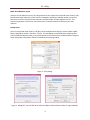
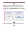
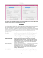
Most modules, except for "Format TEXT data" and "Make Common Seismic Gathers", are accessible
within the same "Utility" dialog (Figure 1). The other two modules have their own separate dialogs as
illustrated in Figure 2. The type of task each module performs is briefly explained below.
Format SEG-2 Files
The basic and minimum input data element for PS is one record that consists of a suite of an individual
channel's recordings, called "traces." The field records should be saved in the SEG-2 format (Pullan,
1990), which is an engineering standard that most engineering seismograph have adopted as the default
output format. Other text data files can be converted to the PS format by using a conversion module
("TXT2PS") that can be foud under "Utility" in the main menu. All SEG-2 records are internally converted
to PS format as soon as they are imported by the program, and all intermediate and final outputs of
seismic data sets will be in this PS format.
All SEG-2 records imported by the ParkSEIS (PS) software are first internally converted to another format
called "PS format" that is a modification of the "KGS format (or modified SEG-Y format)" (WinSeis User's
Manual, 1997). This conversion is necessary to handle seismic data in a faster and more accurate
manner for advanced and non-conventional wavefield operations commonly used in various stages of
MASW data processing. In PS format, each channel's data set (called a "trace") is saved as a combination of a header (of 120 elements of 2-byte integer each), followed by data samples (of 4-byte floatingpoint value each). A complete listing of the "PS Header" can be displayed by choosing "PS Header" on
the main menu's "Info" item. All output of seismic data are saved in PS format with the "DAT" extension
(e.g., "Output.dat").
2
PS - Utility
Format TEXT data
Sometimes, seismic data are prepared from a variety of different sources that may include seismographs
from different manufacturers, output from numerical modeling, etc. In spite of different data formats
adopted in each case, they can be at least prepared in text format. When that is done, these text data
samples can be converted to PS format by using this module.
Make Common Seismic Gathers
A normal seismic record in either SEG-2 or PS format has a collection of seismic data that were
generated from the same seismic source ("shot"). Therefore, it is also called a "common shot gather." A
collection of multiple common shot gathers (i.e., a normal seismic data file in PS format) can be
rearranged into different types of "common" gathers based on the primary sorting index. This module
can rearrange input seismic data of any type (e.g., common-shot gathers, common-offset gathers, etc.)
into the following types of common gathers: offset (CO), receiver station (CRS), source station (CSS),
source-receiver mid points (CMP), field record number (CFR), recording channels (CRC), and header
word (CHW). In the case of common header word (CHW) gathers, a header word number is specified
that is used as the primary sorting index to generate different output records. Usefulness of the
common-offset (CO) gathers is further explained in the PS User Guide "Back-Scattering Analysis (BSA)
and Common-Offset (CO) Sections."
Make Seismic Walkaway Record
It is sometimes useful to make a seismic record of an extended offset (i.e., source-receiver distance)
range simply by combining multiple records obtained at the same surface location but with different
source offsets. This "extended offset" record is called a walkaway (or noise analysis) record (Telford
et al., 1976; Sheriff, 2002). In seismic data analysis, a walkaway record can be extremely useful in
understanding the behavior of seismic body and surface waves in their propagation velocities and
attenuation properties. Furthermore, it can produce a dispersion image of an increased resolution
achieved by the extended aperture (i.e., offset) of measurement that can delineate multi-modal
dispersion patterns more clearly.
Edit Seismic-Data Trace Header
It is sometimes necessary to change one or more of trace header elements to accommodate some
experimental modifications or to rectify some minor error introduced during the previous processing
(e.g., changing distance unit from feet to meters). This module can accomplish such a task.
Stack (+/-) Seismic Records
This module can stack two different records by summing (+) or subtracting (-) data values. A scaling
factor can be applied to each record, if necessary, before the operation. This module can be useful
when handling seismic records and dispersion image records (also called "overtone" records) to meet
some experimental purposes.
3
PS - Utility
Make 2D Vs Map from Layers
Inversion of one dispersion curve (*.dc) will generate its own output of one layered-earth model (*.LYR).
The 2D shear-wave velocity (Vs) cross section is created by combining a multiple number of such LYR
files at the end of the inversion that processed a multiple number of input dispersion curves. This
module can generate such a 2D Vs cross section from a multiple number of LYR files of your own
selection.
Remap Layers
One or more layered-earth model (*.LYR) files can be remapped according to a common depth model,
which is defined by another "reference" LYR file. This remapping can be useful when comparing files
(LYR's) of different depth models, or constructing a 2D Vs cross section from multiple LYR files to bypass
some unfavorable interpolation effects introduced by the plotting module.
Figure 1. Utility dialog.
Figure 2. Dialogs for "Format TEXT data" (left) and "Make Common Seismic Gathers" (right) modules.
4
PS - Utility
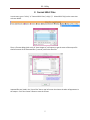
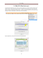
2. Format SEG-2 Files
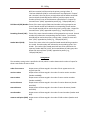
In main menu, go to "Utility" → "Format SEG-2 Files (*.dat)(*.*)." Select SEG-2 file(s) at the same time
as shown below.
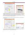
Then, a file save dialog (with a title of "Save Output As") will appear to get the name of the output file
that will contain all the formatted files ("records") within the same file.
Imported files are listed in the "Input Files" box on top left corner that shows the order of appearance in
the output. Click "Run Format" button to start the format.
5
PS - Utility
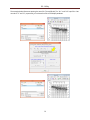
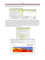
Saved output seismic data of PS format will be displayed. A text window showing the contents of the
"File Descriptor" in the first file of the input SEG-2 files will be displayed also. It lists the name of
another text file that contains the entire format history contents for all the channel's data (i.e., "traces")
["PS(FormatHistory).TXT"], an example of which is displayed below using the Windows Notepad.
6
PS - Utility
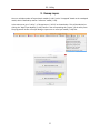
3. Format TXT data
Seismic data in text format can be converted to PS format using this module. In the main menu, go to
"Utility" → "Format TEXT data (*.txt)." Then, import a text file that contains seismic data (and possibly
with header information) in text format.
A control dialog will appear that contains all the controls related to input and output formatted data
that are grouped into four (4) different steps as shown below.
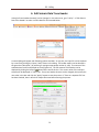
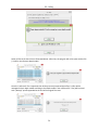
STEP 1
Select the way text data are arranged in the input file. Input text data can be arranged in one of the two
formats—serial or parallel. If data values are arranged one trace after another, possibly with a common
header at the beginning of each trace, then it is regarded as "serial" format. On the other hand, if one
line of text in the input file contains data values for all traces at one time sample without header information, then it is regarded as "parallel" format. Move to the next step by selecting the "STEP 2" tab.
7
PS - Utility
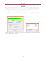
STEP 2
Specify input header information here. If there is a file header at the beginning of the input file, then its
number of elements can be specified in "# of file header elements" box. If each trace has its own
header of common format, then the total number of trace header elements can be specified in the "# of
trace header elements" box. If there are no file or trace headers, then the corresponding box should
show a value of "0". The total number of traces is specified in the "# of traces" box, and the total
number of data samples per trace is specified in the "# of data samples per trace" box. The sampling
interval can be specified in the "Sampling interval in millisecond (ms)" box. An arbitrary number can be
assigned in the "Record number" box that will be the output record number. Move to the next step by
selecting the "STEP 3" tab.
STEP 3
Specify output file name here. If formatted output data are to be added at the end of an existing file,
then check "Append output" box. Make sure existing data and the new data have the same number of
samples per trace and also the same sampling interval.
STEP 4
Click "RUN" button to start the conversion. Converted output will be displayed.
8
PS - Utility
4. Make Common Seismic Gathers
In the main menu, go to "Utility" → "Make Common Seismic Gathers" as shown below. Then, the
control dialog will appear in which the specific type of output gather (e.g., common-offset gather) can
be selected. If the type of output gather is already known, then go to "Utility" → "Make Common
Seismic Gathers of" and select the appropriate option as also illustrated below.
Then, import a normal seismic data file of PS format that has source/receiver (SR) setup encoded [i.e.,
"*(SR).dat"] as illustrated below. If the input file does not have such information encoded, then the type
of output gather will be limited.
9
PS - Utility
The input file name is displayed in the top box, which can be replaced by clicking the button (
at the end of the box. All controls are arranged in three (3) tabs.
) placed
Type of gather
Type of output gather is selected here. If the type was already known and selected from the main menu,
then the corresponding option will have been selected and the next tab, "Arrangement", will be
displayed. "Type of gather" will determine the primary information that will be used to make a common
collection of traces to be grouped as one "record" in the output file. [Secondary information that will be
used to determine the order of arrangement within the same record will be selected next in the
"Arrangement" tab.]
Offset (CO)
Traces of the same source distance (also called "offset") will be grouped as
one record. Record number will indicate the corresponding offset
multiplied by "10" (e.g., 1000 for common-offset of 10 meters). Trace
header word #19 will be used as the primary sorting index. Output file
name will have "(CO)" appended as postfix [e.g., "Output(CO).dat"].
Receiver Station (CRS)
Traces of the same receiver locations (i.e., the same receiver station
numbers) will be grouped as one record. Record number will indicate the
corresponding station number. Trace header word #86 will be used as the
primary sorting index. Output file name will have "(CRS)" appended as
postfix [e.g., "Output(CRS).dat"].
Source Station (CSS)
Traces of the same source locations (i.e., the same source station numbers)
will be grouped as one record. Record number will indicate the
corresponding station number. Trace header word #87 will be used as the
primary sorting index. Output file name will have "(CSS)" appended as
postfix [e.g., "Output(CSS).dat"].
Mid-Point (CMP)
Traces of the same source-receiver-mid-point locations will be grouped as
one record. Record number will indicate the sum of both source and
receiver station numbers. Trace header words #86 (receiver station) and
10
PS - Utility
#87 (source station) will be used as the primary sorting indices. If
"Common-Mid-Point (CMP) in surface distance" box displayed in "Output"
tab is checked, then the primary sorting indices will be header words #36
(receiver distance) and #39 (source distance), and the output record
number will be the sum of both distances multiplied by 10. Output file
name will have "(CMP)" appended as postfix [e.g., "Output(CMP).dat"].
Field Record (CFR) Number Traces of the same original field record numbers will be grouped as one
record. Record number will indicate the corresponding record number.
Trace header word #6 will be used as the primary sorting index. Output file
name will have "(CFR)" appended as postfix [e.g., "Output(CFR).dat"].
Recording-Channel (CRC)
Traces of the same channel numbers will be grouped as one record. Record
number will indicate the corresponding channel number. Trace header
word #8 will be used as the primary sorting index. Output file name will
have "(CRC)" appended as postfix [e.g., "Output(CRC).dat"].
Header-Word (CHW)
Traces of the same value in the specified header word# will be grouped as
one record. Record number will indicate the corresponding value in the
header. The number (#) of header word will have to be specified in the
separate "Header Word # (1-120)" box located below the radio group box.
Output file name will have "(CHW)" appended as postfix [e.g.,
"Output(CHW).dat"].
Arrangement
The secondary sorting index is specified in this tab, which is used to determine the order of output for
those traces within the same record.
order of occurrence
Output traces will be arranged in the order of their appearance in the
original input file.
receiver station
Output traces will be arranged in the order of receiver station numbers
(header word #86).
source station
Output traces will be arranged in the order of source station numbers
(header word #87).
receiver distance
Output traces will be arranged in the order of receiver distances (header
word #36).
source distance
Output traces will be arranged in the order of source distances (header
word #39).
record number
Output traces will be arranged in the order of record numbers (header word
#92).
common-mid-point (CMP) Output traces will be arranged in the order of CMP numbers (header word
#12).
11
PS - Utility
Output
Output traces can be written either in an "increasing number" order or a "decreasing number" order of
the values selected as the secondary sorting index in the "Arrangement" tab. "Min. number of traces in
each gather" will determine the smallest number of output traces within a record and will not output
those records with a lesser number of traces. The "Common-Mid-Point (CMP) in surface distance"
check box will be enabled if "Common-Mid-Point (CMP)" is selected as the primary sorting index. If this
box is checked, the output CMP (header word #12) will be encoded as a sum of source and receiver
distances.
Click "OK" to start the process that will ask for the output file name, if not previously specified.
Output will be displayed in a new window. The common-offset gathers will be displayed in the
"variable-area" format as default mode of display. Display can be changed back to the normal black &
white wiggle-type display by depressing the "Variable Area Display" button in "View" tab of the top tool
panel.
12
PS - Utility
5. Make Seismic Walkaway Record
In main menu, go to "Utility" → "Make Seismic Walkaway Record" as shown below. A dialog with all
control options will appear with a brief instructional message as illustrated below. Input records are
opened in the order of their appearance in the output walkaway record from "left" to "right" as the
output is displayed in a separate window.
Click the "Open File" button in a separate tab to import one input record. This procedure always starts
from "#1" tab and moves to next tab progressively (e.g., "#2", then "#3", etc.) up to maximum five (5)
tabs. The same file can be used to open in each tab. Then, different records have to be selected in each
of the input display windows (e.g., "Record #1", "Record #2", etc.). The display order of traces in each
input window can be changed (i.e., "flipped") by checking the "Flip Horizontally" box in each tab.
13
PS - Utility
The example below illustrates opening the same file ["Line1(SR).dat"] for "# 1" and "# 2" input files. But
records of "5" and "8", respectively, are selected in each of the display windows.
14
PS - Utility
Check the "Use displayed traces only" box to use only part (not full) of the traces in the input record. To
select these traces, use the "Zoom In" button in the "View" tab of the top tool panel. Then, only those
selected (i.e., displayed) traces will be included for the generation of the walkaway record. The full
length of time will be used for these selected traces regardless of the displayed lengths. Record number
of the output can be specified in the "Output Record #" box.
Click "Make" button to generate the walkaway record that will be displayed in a separate window as
illustrated above.
Click "Save" button to save the displayed walkaway record as a separate file. If necessary, it can be
appended to an existing file by checking "Append Output" box.
15
PS - Utility
6. Edit Seismic-Data Trace Header
Value(s) of trace header element(s) can be changed. In the main menu, go to "Utility" → "Edit SeismicData Trace Header" to select a seismic data file as illustrated below.
A control dialog will appear with following options available. At any time, the input file can be replaced
by a new file by clicking the "Open (*.dat)" button in the dialog. The header word # can be selected in
the green box ("Word No.") by selecting or typing an appropriate number (1-120). The content of the
selected element will be displayed on the top green bar. The full contents of PS headers can be
displayed by clicking the button ( ) placed at the end of this bar. The current value of the selected
element will be displayed in "Value" box. If only one header element is to be changed, then specify the
new value in this box and click the "Apply" button to start the process. If "Save as a separate file" box
has been checked, then it will ask for output file name before starting the process.
16
PS - Utility
If any common properties such as distance unit, sampling interval, record number, etc., are to be
changed, then check the "Enable multi-edit option" box so that the additonal options listed in the
separate tabs at the bottom of the page will be enabled.
Coordinates/Stations
To change coordinate(s) (i.e., distances) of source and/or receivers, select the "Coordinates (X, Y, Z)" tab,
check the appropriate box(es) ("Receiver" or "Source"), and enter the amount of change in the "Value"
box. Select the type of change by selecting the proper type ["Add (+)" or "Multiply (x)"].
To change station(s) of source and/or receivers, select the "Stations" tab and check the appropriate
box(es) ("Receiver" or "Source") and enter the amount of change in the "Value" box. Select the type of
change by selecting the proper type ["Add (+)" or "Multiply (x)"].
17
PS - Utility
Type/Range
The type of data (determined by the value in header word #1) can be changed by selecting an appropriate type in the "Data" radio group box. The type of receiver array (1D or 2D) can be selected in the
"Rcv array" box. The MASW survey type (e.g., active, passive, and active/passive combined types) can
be changed by selecting an appropriate option in the "MASW survey" radio box.
The range of records and traces to which the change will be applied can be specified in the "Record" and
"Trace" boxes, respectively.
Click the "Apply" button to start the process. If "Save as a separate file" box has been checked, then the
program will ask for output file name.
18
PS - Utility
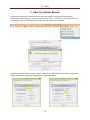
7. Stack (+/-) Seismic Records
Two seismic records can be stacked on top of each other by either summing two amplitudes or
subtracting one from the other. In the main menu, go to "Utility" → "Stack (+/-) Seismic Records" and
the utility form with the "Edit Record(s)" tab selected will appear as shown below.
Open two seismic data files by clicking "Open 1st Record" and "Open 2nd Record" buttons, respectively,
as illustrated below. Each file will be displayed in a separate window.
19
PS - Utility
Check the "Apply to all records" box if individual records are to be stacked on top of each other in the
order they appear in each file. Otherwise, the records displayed in each window will be stacked.
Choose the "Stack Type" (i.e., + or -) and adjust relative amplitude ratios, if necessary, in the "Amplitude
Ratio" box. These ratios will be applied to each record before the operation. Check the "Append
output" box if output records are to be added at the end of an existing file.
Click the "Run Stack" button to start the process. The program will ask for the output file name and
then display output in a separate window as illustrated below.
20
PS - Utility
8. Make 2D Vs Map from Layers
A 2-D shear-wave velocity (Vs) cross section can be generated from a multiple number of layered-earth
models (*.LYR). In the main menu, go to "Utility" → "make 2D Vs Map from Layers (*.LYR's)" that will
request to import multiple files of LYR extension. The files can also be imported from the utility form by
clicking the "Import Layer Models (*.LYR)" button as illustrated below.
Select multiple files (*.LYR's) at the same time as illustrated below.
21
PS - Utility
The following control dialog will appear. Click the "Output File Name [*(2DVs).txt]" button to specify the
name of the output file that will be saved as a text file.
Check "Export confidence data if exists [*(2DConf).txt]" box to make the corresponding 2D confidence
(%) cross section map. If input layered-earth files were created from the inversion process, then each of
them will contain the inversion confidence information (as well as the surface coordinate of the original
seismic record) that will be used to generate the map. Output will be appended to an existing file (*.txt)
if "Append output*" box is checked. In this case, the existing data for the same surface coordinate(s)
will be replaced by the new output data. Click the "OK" button to start the process that will display the
output in a separate window as illustrated below.
22
PS - Utility
9. Remap Layers
One or a multiple number of layered-earth models (*.LYR's) can be "remapped" based on the new depth
model, which is defined by another "reference" model (*.LYR).
In the main menu, go to "Utility" → "Remap Layers (*.LYR's)" as shown below. This will be identical to
clicking the "Open Layer Model(s) (*.LYR)" button in the corresponding tab ("Layers") of the utility form.
The program will invoke a file open dialog to import one or more layer model (*.LYR) files.
23
PS - Utility
Select all files at the same time as illustrated below. After that, the program will ask to open another file
(*.LYR) for the reference depth model.
Once the "reference" file is imported, then all the previously imported input files (*.LYR's) will be
remapped in their depth model according to the depth model in the reference file. They will be saved
with "(Remap)" postfix appended at the end of the original file name.
24
PS - Utility
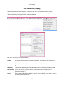
10. Show Utility Dialog
All previously explained tasks, except for "3. Format TEXT data" and "4. Make Common Seismic
Gathers", can be accessed in the utility form. To open these tasks from the main menu, go to "Utility" →
"Show Utility Dialog" to display the form as illustrated below.
Each tab in the utility form is explained below.
Format
This tab contains the module to perform the task of "Format SEG-2 Files" explained in
section 2.
Header
The module to perform "Edit Seismic-Data Trace Header" explained in section 6 is in this
tab.
Walkaway
"Make Seismic Walkaway Record" explained in section 5 can be performed in this tab.
Edit Record(s) The task of "Stack (+/-) Seismic Records" can be performed in this tab, which is
explained in section 7.
Layers
The two tasks of "Make 2D Vs Map from Layers" (section 8) and "Remap Layers" (section
9) can be performed in this tab.
25
PS - Utility
11. References
Pullan, S.E., 1990, Recommended standard for seismic (/radar) files in the personal computer
environment: Geophysics, 55, no. 09, 1260-1271.
Sheriff, R. E., 2002, Encyclopedic dictionary of applied geophysics (4th ed.): Society of Exploration
Geophysics (SEG), Tulsa, OK, 427 pp.
Telford, W.M., Geldart, L.P., Sheriff, R.E., and Keys, R.A., 1976, Applied geophysics, Cambridge Univ.
Press, 860 pp.
WinSeis User's Manual, 1997, Kansas Geological Survey, University of Kansas, Lawrence, KS.
26