1
information. In the Wiegand mode the serial port is able to
receive the data directly from any Wiegand device, such
as card reader and also output the data in the Wiegand
format, as if it was a card reader itself [2]. Wiegand
interface is popular in the security, access control, and
automation industry. The OEM Wiegand converter
requires a regulated power source of 5 VDC or 8*16VDC,
100mA
for
internal
operation.
The
RS*232
communications parameters are: 9600 baud, N no parity, 8
data bits, 1 stop bit and no hardware flow control [3].
Wiegand converter operates with any card reader that
produces a standard Wiegand (Data 1 / Data 0 or Clock
and Data) communication output. Wiegand format is easy
to use, no need to deal with clock. We have designed to
pick out Wiegand format to get data from card reader and
then convert Wiegand data transmit to PIC controller via
RS232 connector. A 26 bit Wiegand format will be used
in the example below.
Input: Wiegand (26*bit)
1 001011010100101100011010 1
Even Parity
Data
Odd Parity
Output: 16*byte ASCII string from RS232 method
00002D4B1A
3 CR
*26#
26*bit Wiegand Data ((2D4B1Ahex) Parity Character
D. Power Supplies
Power Supplies for hardware designed specifically for
the system equipment installed. The MaxiProx 5375
reader requires a linear power supply with a rating of 24 *
28.5 Volts DC at a minimum of 1.5 Amps per reader. A
linear power supply aids maximum reader performance.
The Wiegand converter requires a regulated power source
of 5 VDC or 8*16VDC, 100mA for internal operation. The
reader and reader converter interface has shared 12VDC
power supply. RFID card utilities power from the reader
through radio frequency.
IV. THE SPEAKER RECOGNITION
Simply put, voice recognition is the act of recognizing
an identified speaker’s speech and converting it into text.
In particular, voice recognition systems have to be trained
to a specific user, combining the principles of both
speaker recognition (identifying the speaker) and speech
recognition (determining what words the speaker is
saying). The development of voice recognition systems,
especially their training methods, is mostly due to the fact
that human speech patterns vary from person to person.
Accents, in particular, cause these differences to emerge in
basic speech recognition systems, causing them to behave
in ways not intended. The key difference between the two
components to voice recognition is that speaker
recognition is the process of recognizing the identity of
the speaker whereas speech recognition is the process of
determining what is said by a speaker. We will be using
speaker recognition methods. The basic operation of
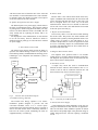
speaker recognition is shown in figure 3.
MIC
Input
Input
Filtering
Noise3filtered
voice input
Feature
Selection
Decision
Pattern
Matching
Voice Input
Features
Match
Result
Voice Profile
Database
Fig.3.
Basic Operation of Speaker Recognition
A. Texas Instrument MSP430
The Texas Instruments MSP430 Ultra*Low Power
MCUs are known for their ease of use and low power
consumption. A microcontroller is necessary to interface
the PIC subsystem with the Scientific Instruments Speech
Recognition circuit SR*06. The microcontroller and SR*06
collectively handle user profile management.
B. Images Scientifics
Recognition Circuit SR)06
Instruments
(SI)
Speaker
The SI SR*06 circuit is an unassembled speech
recognition circuit. An alternative is the SR*07 speech
recognition circuit, which provides the exact same
functionality as the SR*06 but comes fully assembled.
Consequently, the SR*07 is more expensive, so for the
purposes of cost*effectiveness we used the SR*06 speech
recognition circuit. Both circuits utilize the HM2007
speech recognition IC. It is a speaker dependent chip
capable of recognizing up to 40 .96*second words or 20
1.92*second words [4].
C. Voice profile
Voice profiles, as stated earlier, will be collectively
managed by the combination of the MSP430 MCU and
the SR*06 Speech Recognition circuit. User identification
will be hard*coded into the MCU based on the passphrase
location the user selects on the SR*06. Program flow for
speaker recognition can describe as follow:
The MCU receives a 3*bit user ID from the PIC. The
speaker then speaks into the SR*06. The SR*06 will
recognize the word as one of twenty possible words from
its memory. The SR*06 will then send the value of the
word (either 1 through 20) as a 6*bit output to the MCU.
The MCU will then compare the value from the SR*06