1
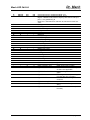
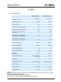
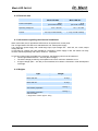
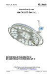
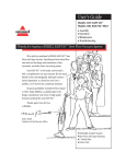
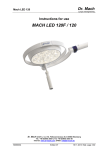
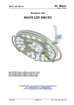
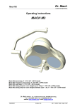
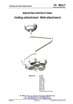
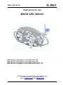
Dr. Mach Mach LED 3MC/SC Lamps and Engineering Instructions for use MACH LED 3MC/SC Mach LED 3MC ceiling light for room heights up to 2,8m Mach LED 3SC ceiling light for room heights up to 2,8m Mach LED 3MC ceiling light for room heights between 2,8m – 3m Mach LED 3SC ceiling light for room heights between 2,8m – 3m Dr. Mach GmbH u. Co., Floßmannstrasse 28, D-85560 Ebersberg Tel.: +49 (0)8092 2093 0, Fax +49 (0)8092 2093 50 Internet: www.dr-mach.com, E-Mail: [email protected] 59180001-MCSC Edition 17 08.05.2013 / Bak page 1/33 Dr. Mach Mach LED 3MC/SC Lamps and Engineering List of contents 1. Safety instructions ..................................................................................................... 5 2. Brief description of the light MACH LED 3MC/SC ..................................................... 7 2.1. Merging of light fields.......................................................................................... 7 2.2. Light intensity control .......................................................................................... 7 3. Light functions operated at the sterilisable handle .................................................... 8 4. Operating the light MACH LED 3MC/SC ................................................................... 9 4.1. Turning the light ON and OFF ............................................................................ 9 4.2. Adjusting the light field with the sterilisable handle ............................................. 9 4.3. Adjusting the light intensity ............................................................................... 10 4.4. Adjusting the colour temperature (Mach LED 3MC only).................................. 11 4.5. Depth light ........................................................................................................ 12 4.6. Integrated OT-laser-pointer (Mach LED 3MC only) .......................................... 12 4.7. Deactivating all functions on the ring of the handle .......................................... 13 4.8. Synchronization and / or communication with the wall panel ............................ 13 4.9. Basic operating mode of the communication on Dr. Mach LED lights .............. 14 4.10. 5. Positioning..................................................................................................... 18 Cleaning ..................................................................................................................18 5.1. Sterilisable handle ............................................................................................ 18 5.2. Lamp housing, protective disk and support system .......................................... 20 6. Maintenance ........................................................................................................... 21 6.1. Periodical maintenance work ............................................................................ 21 7. Troubleshooting ...................................................................................................... 22 8. Data ........................................................................................................................ 24 8.1. Technical data .................................................................................................. 24 8.2. Electrical data ................................................................................................... 25 8.3. Information regarding the electrical installation ................................................ 25 8.4. Weights ............................................................................................................ 25 8.5. Environmental conditions ................................................................................. 26 8.6. Important remarks ............................................................................................ 27 59180001-MCSC Edition 17 08.05.2013 / Bak page 2/33 Dr. Mach Mach LED 3MC/SC Lamps and Engineering 9. CE-mark .................................................................................................................. 27 10. Disposal ............................................................................................................... 27 11. Spare parts .......................................................................................................... 28 11.1. Mach LED 3MC ............................................................................................. 28 11.2. Mach LED 3SC ............................................................................................. 29 11.3. Transformer housing ..................................................................................... 29 12. Spare parts list ..................................................................................................... 30 13. Electromagnetic compatibility .............................................................................. 31 59180001-MCSC Edition 17 08.05.2013 / Bak page 3/33 Dr. Mach Mach LED 3MC/SC Lamps and Engineering Dear customer! Congratulations for acquiring our new OT-light MACH LED 3MC/SC. The new OT-light generation with LED technology supports your professionality by innovative technology and design. The advantages of the LED technology: adjustable light colour, a life-span of minimum 40.000 hours and an almost nonexistent heat development in the surgeon’s head area and in the wound field. The advantages already provided by Dr. Mach’s light technology with halogen and gas discharge lamps have been maintained: natural colour reproduction, exact illumination of the wound field and easy positioning of the light head. 59180001-MCSC Edition 17 08.05.2013 / Bak page 4/33 Dr. Mach Mach LED 3MC/SC Lamps and Engineering 1. Safety instructions Pay attention to the instructions for use when handling the lamp. WARNING: This device has not been designed for use in potentially explosive areas. According to the Medical Device Regulation the light is classified under class I. Store the OT-light in its package for at least 24 hours in the respective room before mounting, in order to equal temperature differences. Please read the instructions for use carefully to make the most of your lighting system and to avoid any damages to the device. The lights may only be repaired and special assembly work may only be carried out on the reflector or sockets by ourselves or a company that has been expressly authorized by us. The manufacturer can only be made responsible for the safety of the light if repairs and alterations are carried out by the manufacturer himself or a company that guarantees to observe the safety regulations. The manufacturer cannot be made liable for personal or material damages if the light is operated inexpediently or incorrectly or used for purposes other than those for which it is intended. The light is to be dismantled from the spring arm in reverse order to its assembly. This may only be carried out after the spring arm has been adjusted in height at horizontal position since the arm is under spring tension and can bounce up. Make sure that the light is in perfect working order before every use. Attention, external power supply! The light works only with an external power supply 250VA. The external power supply used with the OT-light must be tested and validated according to IEC 60601-1. Attention! A main control switch must be installed for turning the system power-off. During the mounting of the OT-lights the entire system (incl. the ceiling attachment) must be disconnected from mains! A later dismounting of the lights from the spring arms or dismounting the sliding contacts inside the arms is to be done ONLY AFTER DISCONNECTING THE ENTIRE SYSTEM FROM MAINS. Otherwise the main control board will be damaged! 59180001-MCSC Edition 17 08.05.2013 / Bak page 5/33 Dr. Mach Mach LED 3MC/SC Lamps and Engineering Symbols and notes used in this user manual: This symbol means possible hazard sources. Please observe also the safety remarks and the hazard specifications mentioned in the mounting instructions and user manuals from Ondal company. This symbol means possible hazard caused by electric current. Please observe also the safety remarks and the hazard specifications mentioned in the mounting instructions and user manuals from Ondal company. This symbol refers to important mounting indications, useful information and operation hints. This symbol indicates to observe the user manual. Alternating current Bulb Fuse Indication on China RoHS / Pollution control Logo China Temperature range for transport and storage Indication for disposal 59180001-MCSC Edition 17 08.05.2013 / Bak page 6/33 Dr. Mach Mach LED 3MC/SC Lamps and Engineering LASER CLASS 2 Keep the laser beam away from the patient’s and employee’s eyes. Danger of injury! 2. Brief description of the light MACH LED 3MC/SC Intended use of the light Mach LED 3MC/SC: The light is used for treatment, diagnosis and in operating theatres. The light is used in medical rooms (groups 0, 1 and 2 according to DIN VDE 0100-710). The light is mounted to the ceiling. Maintenance of the light should be scheduled every 2 years. The light has a fixed electrical connection. The OT-light MACH LED 3MC/SC is available in following versions: Mach LED 3MC with merging of light fields, light intensity control, colour temperature adjustment and laser pointer; Mach LED 3SC with merging of light fields and light intensity control. - Colour temperature adjustment and laser pointer against surcharge. 2.1. Merging of light fields The OT-lights Mach LED 3MC/SC offer light field adjustment by merging the individual light fields of each LED unit by swiveling them. NOTE: This feature is activated by turning the sterilisable handle. 2.2. Light intensity control The OT-lights Mach LED 3MC/SC offer the feature of light intensity control. You can adjust the light intensity between 5% and 100%; according to your requirements 59180001-MCSC Edition 17 08.05.2013 / Bak page 7/33 Dr. Mach Mach LED 3MC/SC Lamps and Engineering 3. Light functions operated at the sterilisable handle Depth light 2 2 The depth light can be activated by a tight-turn of the ring at the sterilisable handle. A left-turn of the ring switches the depth light OFF. The depth light function on the ring is preset by Dr. Mach at delivery. The customer can transfer all other available functions of the LED-light to the ring on request. The transfer procedure is described in the following chapters. Merging of light fields 1 59180001-MCSC 1 The four light fields of the outer LED-units are merged to one light field by turning the handle sleeve. Edition 17 08.05.2013 / Bak page 8/33 Dr. Mach Mach LED 3MC/SC Lamps and Engineering 4. Operating the light MACH LED 3MC/SC 4.1. Turning the light ON and OFF The push button 1 on the control panel turns the light Mach LED 3MC/SC ON and OFF. 4.2. Adjusting the light field with the sterilisable handle The light field can be adjusted by turning the sterilisable handle 2. 2 3 59180001-MCSC The current size of the light field is shown by the digital display 3. Edition 17 08.05.2013 / Bak page 9/33 Dr. Mach Mach LED 3MC/SC Lamps and Engineering 4.3. Adjusting the light intensity 6 4 5 Select the desired light intensity before surgery. It is recommended to start with 80% of the maximum light intensity and to increase the light intensity in time. At these models the adjustment is done by the control panel at the cardanic bow. The intensity can be adjusted between 5% and 100%. By pressing push button 4 the light intensity decreases. By pressing the push button 5 the light intensity increases. The current light intensity level is shown by the digital display 7. ENDO-Light By pressing the push button 6 the outer LED-units turn off while the central unit continues to burn. The ENDO-light function can be deactivated by pressing the button 6 again. When the ENDO-light function is activated, the colour temperature information is faded out on the display of the light. 7 Step 2 Transferring the light intensity adjustment function to the ring of the handle Step 1 In order to transfer the light intensity adjustment function to the ring of the sterilisable handle, press first push button 4 or 5 and then the ON/OFF button on the key pad. The frame around the light intensity level display is blinking. The previous function on the ring is deactivated. A right-turn of the ring at the handle increases the light intensity by one step; a left-turn of the ring decreases it with one step. 59180001-MCSC Edition 17 08.05.2013 / Bak page 10/33 Dr. Mach Mach LED 3MC/SC Lamps and Engineering 4.4. Adjusting the colour temperature (Mach LED 3MC only) Five different colour temperature values can be set at the control panel on the lamp housing: 3750, 4000, 4250, 4500 and 4750 Kelvin. The surgeon has the possibility to choose the optimum OR light according to the tissue type and the wound field texture. 8 9 By pressing push button 8 the colour temperature decreases. By pressing the push button 9 the colour temperature increases. The set colour temperature is shown by the digital display 10. 10 Transferring the colour temperature adjustment function to the ring of the handle Step 2 In order to transfer the colour temperature adjustment function to the ring of the sterilisable handle, press first push button 8 or 9 and then the ON/OFF button on the key pad. The colour temperature display is blinking. Step 1 The previous function on the ring is deactivated. A right-turn of the ring at the handle increases the colour temperature by one step; a left-turn of the ring decreases it with one step. This function is not available for the Mach LED 3SC lights. 59180001-MCSC Edition 17 08.05.2013 / Bak page 11/33 Dr. Mach Mach LED 3MC/SC Lamps and Engineering 4.5. Depth light 11 You have the possibility to increase the light intensity of the central segment of the OT-light. This enables an optimum illumination of the wound field according to its texture and the shadowing effects. This is very important in case of small and deep wound channels. To activate the depth light press push button 11 on the control panel. 4.6. Integrated OT-laser-pointer (Mach LED 3MC only) The built-in laser pointer always indicates the middle of the light field and helps the surgeon to find the optimal position of the OT-light to the wound field. The push button 12 on the control panel turns the laser pointer ON and OFF. OT-laser-pointer The integrated laser pointer can be activated by a left-turn of the ring at the sterilisable handle. The laser pointer turns off after approx. 30 seconds. When the laser –pointer is turned on the light intensity decreases automatically by three steps. This is shown also by the digital display. The light intensity can still be adjusted. After the laser-pointer is turned off the light intensity increases to the initial setting. 12 LASER CLASS 2 Keep the laser beam away from the patient’s and employee’s eyes. Danger of injury! The Mach LED 3SC has no integrated laser-pointer. It is available against surcharge. 59180001-MCSC Edition 17 08.05.2013 / Bak page 12/33 Dr. Mach Mach LED 3MC/SC Lamps and Engineering Transferring the colour laser pointer function to the ring of the handle Step 2 In order to transfer the laser pointer function to the ring of the sterilisable handle, press first push button 12 and then the ON/OFF button on the key pad. The “LASER” display is blinking. Step 1 The previous function on the ring is deactivated. A right-turn of the ring at the handle activates the laser pointer; a left-turn of the ring turns it off. 4.7. Deactivating all functions on the ring of the handle Step 2 Step 1 The functions on the ring of the handle can be completely deactivated. Press first of all push button 6 (ENDO) and then the ON/OFF button on the key pad. The ring on the handle is without function. In order to transfer a function on the ring, please proceed as described in the chapters before. 4.8. Synchronization and / or communication with the wall panel The lights Mach LED 5MC/SC can be equipped against surcharge with the function of synchronization (combinations only) and / or communication with a wall panel. The synchronization of two, three or four OTlights enables the transmission of the light intensity or color temperature values set at one light to the other OT-lights. Additionally, the communication allows operating the single lights from a wall panel. The settings from the wall panel can be transmitted to the other lights by pressing the „SYNC“ button. The transmission of the settings to the other lights is done by pressing the „SYNC“ button on the key pad. 59180001-MCSC Edition 17 08.05.2013 / Bak page 13/33 Dr. Mach Mach LED 3MC/SC Lamps and Engineering 4.9. Basic operating mode of the communication on Dr. Mach LED lights The communication of the Dr. Mach LED lights is realized with a single-wire bus. The members of the communication bus have star-shaped connections. All the members of the communication bus need an explicit communication number which is to be set with the first two dip-switches on the control board. Due to the fact that two dip-switches are reserved for addressing, maximum four independent lights can be connected to the communication bus. The communication number of each light is pre-set by the factory and can be changed during installation on site only by opening the light head. The communication number is shown by the sticker “Sync address” on each 5-pole light head. Usually at Dr. Mach the LED 3 lights have the pre-set sync address = 0 and the LED 5 lights have the pre-set sync address = 1. Although the sticker is labeled “Sync Address”, it refers not only to the communication between the light heads, but also to the communication to the wall panel. The light heads of a system must have different sync addresses, otherwise the communication is not working perfectly. If it is known after placing the order that a combination LED 3 / LED 3 and another combination LED 5 / LED 5 was ordered, these combinations will be pre-set with different sync addresses. This way it is ensured that the lights must not be opened at installation. It means also that in case of deliveries with many lights for many operation theatres it must be observed very carefully, which lights are going to be combined. The communication of the lights with the wall panel works with the same single-wire bus. On the control board inside the wall panel there is the dip switch 4 which defines that this control board is working as a wall panel. The dip switch inside the wall panel must be in “ON” position. The control boards inside the wall panel must have the same sync address as the lights they are assigned for. The same communication address on the control board inside the light and the control board inside the wall panel makes sure that the communication with the wall panel is working. Technical remarks regarding the communication The communication between the lights and between lights and wall panels is working through one cable. The voltage on this cable in standby modus is approx. 5-6V. The communication wire can be found on the control board besides the connections for the power supply. The wire leads directly to the controller chip. The controller pin is quite sensitive to negative voltages. This means that if there is a negative voltage bigger than –0,3V on the communication pin, this pin gets damaged and lies on a voltage of approx. 1V. After a correct installation and during regular operation no negative voltages occur. However, during the light installation and wiring equalizing currents can appear, which lead to a negative potential on the communication pin relative to the 0V wire. In this case the pin gets damaged. This is the reason why during installation the power supply of the entire system must be completely switched off and there must be no residual energy in the capacitors (electronic power supply and light head). The electronic power supplies are equipped with quite big-sized capacitors, which have high voltages for several minutes after switching off the primary voltage. The capacitors must be discharged before the communication lines of the light and the wall panel are connected. The reference potential for the communication is the 0V wire of the power supplies. Due to the fact that each light needs its own power supply, the 0V wires of the power supplies must be connected to each other in order to create the same reference potential for the communication. Usually the wiring on the flange is factory-made. However during installation it should be observed that the 0V wires of all the power supplies that are used for lights with communication, are bridged. The protective conductor (green-yellow) has no use for the communication. There must not be any connection between the protective conductor and the communication line, because it cannot be ensured that the protective conductor has a 0V potential all the time. In case the communication line is in contact with the protective conductor due to an installation error it is possible that the communication does not work correct. Eventually the function failure is not directly visible and consists of sporadic malfunction or repeated pressing of the keys on the keypad in order to control the light. 59180001-MCSC Edition 17 08.05.2013 / Bak page 14/33 Dr. Mach Mach LED 3MC/SC Lamps and Engineering Information about the power supply The Dr. Mach LED lights need a direct current voltage of 24V-30V DC for correct operation. The undulation of the direct current voltage should not exceed 5%. The LED control inside the light is currentoperated, that means that a change of the supply voltage does not lead to a change of the light intensity. Due to the fact that the power requirement of the light is constant, an increase in the supply voltage means a decrease of the total current of the light and therefore to a decrease of the heat development inside the light. That is why it is recommended to supply the light with a high voltage, so the life span of the component parts is not shortened by an exceeding heat development. The control electronics of the light has an initial voltage at starting of approx. 17V. This voltage value is too low for the light operation. The light can be operated with 20V DC for a short time, but in this case the heat development will be very high, which has a negative influence on the life span of the component parts. The initialisation phase of the control electronics is approx. 1 second. In case that the supply voltage does not reach 24V-30V within this second, the cluster board of the lights can be damaged. This is the reason why a soft start, which makes sense for halogen lights, is not allowed for LED lights. The capacitances inside the light and the LED control cause quite high current peaks when turning on the power supply. The current peaks are in the range of the sevenfold rated current. A current limiting and a protection of the lights should not delimitate the current peak, because the electronic boards would eventually consider this delimitation as a failure in power supply and would change to emergency operation mode. The emergency operation mode does not ensure a normal functionality of the lights and must be avoided. Swapping the polarity at the LED light does not lead to a malfunction. After the polarity is changed, the light works perfectly. A wrong polarity can happen by swapping the wires inside the spring arm, horizontal arm or ceiling flange tube, but also inside the transformer housing or the light. The error code for wrong polarity on the light display is C0--. The display is on, but the light is not working. If the polarity is swapped only at one of the lights and the lights are equipped with communication, caution is advised when changing the polarity at the ceiling flange. If the polarity at the power supplies is correct and the polarity on the ceiling flange is changed only for one light, it may happen that due to the bridge between the 0V lines of the power supplies the 28V line of one power supply is connected to the 0V line of the other power supply. The function of the lights is OK, the connection of the power supplies is not. The power supplies are working one against the other. Troubleshooting If a communication error on an installed system must be found, first of all the neutral point, where all communication lines are connected, must be disconnected. The disconnection must be done only after the primary supply voltage was turned off. On the free lines the opencircuit voltage must be checked. After switching on the supply voltage all displays must work and the voltage measured on every communication line must be 5V-6V. The voltage is measured with the OV line of the power supplies (normally the blue terminals on the flange). If the measured voltage is not correct (i.e. 1V), the communication pin is damaged and the control board of the light must be exchanged. If the measured voltage is 0V, the line is not connected to the communication pin of the control board. If the measured voltages are correct, please connect first of all the communication lines of the lights and check their correct function. If there is a wall panel on site, do not connect it yet to the communication line. Transmit the values of one light to the other lights and check the function. If the communication is not working, the malfunction must be located in the light attachment. In order to resolve the problem, the spring arms, the horizontal arms and the ceiling tube cables must be changed individually and one after another. If the communication between the lights is working, the wall panel can be connected and the function can be tested. If the communication is not working, please check the connections in the wall panel and the settings of the DIP switches. Please look also for damaged crimp connections, where single strands can cause a short circuit. 59180001-MCSC Edition 17 08.05.2013 / Bak page 15/33 Dr. Mach Mach LED 3MC/SC Lamps and Engineering Installation instructions for LED-lights with communication / synchronization After installing the ceiling flange, the central axis, the horizontal arm and the power supplies, the lights must not be mounted to the spring arms yet. Insert the 5-pole test adapter into the spring arm. The test adapter can be purchased at Dr. Mach. Then the ceiling attachment is connected to mains. On the marked terminals of the test adapter the voltages + 28V DC and 0V must be checked. In the next step it must be checked if there is a connection between the communication wire on the test adapter and the corresponding wires on the ceiling flange. The communication wires on the flange are not yet connected. All the communication wires in the flanges are loosen. If the supply line with + 28V and 0V is correct, the light head can be mounted and connected. That means that the test adapter has to be removed and the light head has to be connected. Before connecting the light head please disconnect the ceiling attachment from mains. That means that the power supply must be disconnected from mains on the primary side. After disconnecting from mains please wait 20-30 seconds, until the capacitances on the power supplies are discharged. In order to speed up this process, the light can be turned on. After the light head has been mounted and connected, connect the power supply to the mains and check the function of the light. All the functions on the keypad must work, there must be no error code on the display, no triangle must be shown on the display. If the light function is OK, then proceed the same way with the other lights of that ceiling attachment. The communication wires are not yet connected. That will follow with the next step. After all the lights of the ceiling attachment are working, please measure the voltages on the communication lines. The measured voltage on the communication line must be between 5V and 6V. The voltage must be measured between the communication line and the blue terminals on the flange. This is the 0V line (or in correct electrical terms the minus-line). If these 5-6V are not measured on the communication line, then there is a fault on the communication line. In the worst case the communication pin on the control board is damaged. If the communication pin on the control board is damaged, the measured voltage is 0,6V up to 1,2V. The 5-pole sliding contacts have 3 supply lines, one communication line and a fifth line which is not allocated today. This fifth line is not connected in the light head either. There must not be measured any potential on this line. This means that in case a measurement is done on this line, the measured value must be 0V. Due to the possibility of checking the lines by measuring the potential on them, the colour markings of the wires are no longer the only criteria to install and connect the lights in a correct way. Unfortunately we discovered that in the past the colours have been swapped because of changes of the colours of the wires and because of wiring errors at spring arms and horizontal arms. In case the 5-6V are measured on the communication lines of each single light, it means that the communication line is working correctly. Please disconnect the primary side of the power supplies from mains again, so all light heads are current less. Please wait again for 20-30 seconds, until the capacitances on the power supplies are discharged. In order to speed up this process, the light can be turned on. Then the communication wires can be connected to the orange terminals on the ceiling flange. 59180001-MCSC Edition 17 08.05.2013 / Bak page 16/33 Dr. Mach Mach LED 3MC/SC Lamps and Engineering After the communication wires have been connected, connect the primary side of the power supplies to the mains and the check the synchronisation function between the light heads. If the synchronisation is working, it means that the wiring of the communication wires is correct and the signal transmission is OK. In case the synchronisation is not working, a troubleshooting must be performed. Assuming that the communication is working and a wall panel must be connected, the next step is to supply the wall panel with 28V DC. The wall panel is connected with four lines. Two of these lines are for the power supply. The lights are turned off, the power supply must be disconnected on the primary side from mains. Wait 20-30 seconds, until the capacitances on the power supplies are discharged. In order to speed up this process, the light can be turned on. Now the supply line for the wall panel is to be connected. Connect these two lines on the ceiling flange, so you can measure + 28V DC and 0V at the wall panel. Do not connect the communication line for the wall panel yet. After the connection has been done, the power supplies are connected to mains. Turn on the lights and check if the wall panel is supplied with power. Please check if all functions are shown correctly on the display. A communication with the lights doesn’t work yet, since the communication line is not yet connected. If the wall panel is working correctly, disconnect the power supplies from mains and wait until the capacitances on the power supplies are discharged. In order to speed up this process, the light can be turned on. Now connect the communication line from the wall panel to the orange terminals on the ceiling flange. Connect the primary side of the power supplies to mains and check if the communication between wall and light is working. 59180001-MCSC Edition 17 08.05.2013 / Bak page 17/33 Dr. Mach Mach LED 3MC/SC Lamps and Engineering 13 4.10. Positioning Use the sterile handle 14 or the handle rails 13 to position the lamp. Use the handle rail to position the lights before the operation. Use the sterile handle for positioning during the operation. This handle can be removed for sterilisation. 13 14 5. Cleaning 5.1. Sterilisable handle At delivery the lamp is equipped with the handle sleeve 13. The handle sleeve is removable and sterilisable. Before using the first time and before every use the handle sleeve must be cleaned, disinfected and sterilised. The handle sleeve must be removed for sterilization: To remove press the lock V and pull off the sterilisable handle sleeve 13 while keeping the lock pressed. To attach, push on and slightly twist the handle until the lock V engages securely. 14 V Handles often become unsterile during an operation. Therefore always keep additional handles available for exchange. Cleaning / disinfection and sterilization Basics Efficient cleaning / disinfection is an essential requirement for effective sterilization of the handle. Within the scope of responsibility for the sterility of the products it should be noted that only sufficiently validated equipment and product specific processes are used for cleaning / disinfection and that the validated parameters are complied with in every cycle. In addition, the hospital / clinic hygiene regulations must be observed. 59180001-MCSC Edition 17 08.05.2013 / Bak page 18/33 Dr. Mach Mach LED 3MC/SC Lamps and Engineering Cleaning / disinfection Cleaning and disinfection must be carried out immediately after use. A mechanised process (disinfector) should be used for cleaning / disinfection. The efficiency of the process used must be recognised and validated in principle (e.g. listed under disinfectants and disinfection procedures tested and recognised by Robert-Koch-Institute / DGHM). When using other procedures (e.g. a manual procedure), proof and process efficiency in principle must be provided within the scope of validation. Proof in principle of the suitability of the handles for efficient cleaning / disinfection was provided using a cyclic cleaning system (Netsch-Bellmed T-600-IUDT/AN, programme 2 for small parts; code B). It is not allowed to use agents / disinfectants, which contain the following substances, as these may cause changes in the material: High-concentration organic and inorganic acids Chlorinated hydrocarbons 2-ethoxyethanol When cleaning / disinfecting, the following procedures must be followed: Zone 1 13B Process Time (sec.) Pre-rinse, external, cold, 10 – 15°C Washing, acidic, external 35°C Draining time Re-rinse, external approx. 80°C Draining time Re-rinse, external approx. 80°C Draining time 45 120 10 *10 *15 *15 15 Zone 2 Washing, alkaline, external, 93°C Draining time Re-rinse, external, acidic, 90°C Draining time Re-rinse, external 90°C Draining time 135 10 10 15 15 15 Zone 3 Drying, external 100 – 120°C 200 Zone 4 Drying, external 100 – 120°C 200 Door open / close & transport (sluice discharge) 60 Cycle time overall ca. 290 5 minutes 28B 4B 41B * When occupying the disinfection zone (washing zone 2), the re-rinse and draining times will depend on the respective objects being washed therein! 59180001-MCSC Edition 17 08.05.2013 / Bak page 19/33 Dr. Mach Mach LED 3MC/SC Lamps and Engineering Sterilisation Only previously cleaned and disinfected handles may be sterilised. The handles are placed in a suitable sterilisation pack (one-way sterilisation pack, e.g. foil / paper sterilisation bags, single or double pack) in accordance with DIN EN 868 / ISO 11607 for steam sterilisation and then sterilised. Use only the sterilisation procedure listed below for sterilisation. Other sterilisation procedures (e.g. ethylene oxide, formaldehyde and low-temperature plasma sterilisation) are not permissible. Steam sterilisation procedure Validated in accordance with DIN EN 554/ISO 11134 Maximum sterilisation temperature 134°C Proof in principle of the handles’ suitability for effective sterilisation was provided using a fractional vacuum process (Euroselectomat 666 by MMM Münchner Medizin Mechanik GmbH, sterilising temperature 134°C, holding time 7 min.) Inspection / durability The sterilisable handle sleeve must be disposed after 1000 sterilisation cycles or at the latest after 2 years and replaced with a new one. The year of manufacture can be determined with the help of a stamping on the inner side of the handle sleeve (like shown in the photo). The stamping in the photo shows the number 12, which stands for the year 2012. 5.2. Lamp housing, protective disk and support system The Dr. Mach OT-lamp system has a high-quality surface, which can be cleaned with conventional cleaning agents. The protective disk 15 is made of a high-quality plastic. Pay attention to the following during cleaning: - Never wipe over the protective disk 15 with a dry cloth (always clean with a wet cloth). - Only use disinfectants with less than 20% alcohol. 15 Alc. 20 % 59180001-MCSC Wipe the protective disk 14 after cleaning with an antistatic, non-fluffy cloth. Edition 17 08.05.2013 / Bak page 20/33 Dr. Mach Mach LED 3MC/SC Lamps and Engineering 6. Maintenance MACH M3 LED lights are supplied with brakes on the suspension fixture and on the lamp housing. Adjust these brakes, if necessary, after installation. If the lamp is difficult to move or if it does not keep its position, the brake forces should be adjusted. Preventive maintenance of the light should be done every two years. This includes a technical and mechanical check-up. Please observe also the manufacturer’s mounting instructions for the ceiling and wall attachment. In order to keep the system easy-running throughout its life span, we recommend that the hinges should be greased once a year with acid-free grease. Attention: Set the height adjustment, if applicable, of the spring arm to horizontal position before dismounting the lamp, (Please observe also the manufacturer’s mounting instructions for the ceiling and wall attachment). Attention: During all maintenance work the light must be disconnected from mains and secured against resetting. 6.1. Periodical maintenance work The following maintenance work / tests has / have to be done every six months: check on defects in paint work; check on fissures at plastic parts; check on deformation of the suspension. The following maintenance work / tests has / have to be done once a year: check the function; electrical safety test; check the suspension. Check and grease the security segment once a year. For adjustments at the ceiling attachment please observe also the mounting instructions “Ceiling attachment with heavy central axis” or “Ceiling attachment – wall attachment”. 59180001-MCSC Edition 17 08.05.2013 / Bak page 21/33 Dr. Mach Mach LED 3MC/SC Lamps and Engineering 7. Troubleshooting In case of a malfunction of the light an error code is shown on the display of the key pad, as shown in the picture on the left. The error codes consist of four digits. The error shown on the display is always the error with the highest priority: Errors of the control board are prior to errors of the cluster boards. Clusters with lower adress have higher priority. General cluster errors are prior to errors of the LED channels. In case of general cluster errors the lower numbers have the higher priority. Decoding Digit 1 c Digit 2 0-7 Digit 3 * Digit 4 * c c 0-7 0-7 - * c c c c c 0-7 0-7 0-7 0-7 0-7 - 0 1 2 3 4 c 0-7 - 5 c 0-7 - 6 c c c c 0-7 0-7 0-7 0-7 0-7 7 8 9 * c 0-7 0-7 1 c 0-7 0-7 2 c 0-7 0-7 4 59180001-MCSC Cluster errors always begin with the letter 'c'; digit 2 is the cluster adress (0-7) No contact to the cluster General cluster error (reported by the cluster); reset by switching ON and OFF Digit 4 = Bit-number oft he error (MADATAID_CANPAR_STATUS_xxx) WDRESET CPU was reset by WD SWRESET SW reset because of fatal error FLASHCRC FLASH CRC error RAMERR RAM test error NOEEDATA no EEPROM data, defaults were used (SerNum etc. lost) EEDEFAULT EEPROM paramater defaults were set (SerNum etc. preserved) EEWRERR EEPROM write error when writing parameters reserved UNDERVOLT 24V supply undervoltage NOCOMM no data received for too long a time LED-error; reset by switching ON and OFF Digit 3 = LED-channel: 0-7 = CW1,WW1,G1,R1,CW2,WW2,G2,R2 Digit 4 = error code, in case of multiple codes they are added (MADATAID_CANPAR_STATUS_LED_xxx) OFFCURR current measured in driver OFF state UNDERCURR open circuit / cannot reach target current OVERCURR short circuit / measured current is too high Edition 17 08.05.2013 / Bak page 22/33 Dr. Mach Mach LED 3MC/SC Lamps and Engineering E F 0-9,A-F 0-9,A-F 0-9 0-9 0-9 0-9 E E E E E E E E E E E E E E E F F F F * * * * * 1 2 3 4 5 6 7 8 9 A b C d E F 0 1 2 3 * * * * * * * * * * * * * * * * * * * * * * * * 0 0 0 0 0 * * * * * * * * * * * * * * * * * * * 0 1 2 3 4 * * 0 5 * * 0 6 * * 0 7 * * * * 0 1 8 0 * * 1 1 59180001-MCSC Control unit error in software-module 0-15 Control unit error in software-module 16-31 Digit 2 = Module code modulo 16 (hex), see source code 'project.h', xxxx_MODULE_ID Digits 3+4 = decimal error code 00..99, see source code 'retval.h' MAIN_ TIMER_ WATCHDOG_ CAN_ CANCOM_ EEDATA_ FLASHCHK_ CONTROL_ CONTROL_REF_ MOTOR_ LEDCTRL_ SWITCH_ MMISLAVE_KEY_ MMISLAVE_LED_ LCD_ USER_ ADCINT_ DIPSW_ CRITVAR_ OK no error ERR general error ERR_ILLEGAL_CASE illegal case state in graph ERR_ILLEGAL_ACT illegal action state in graph E_NULLPOINTER a function has received a null pointer where not applicable E_EXECFLAGNOTFALSE execution flag was not false in graph E_WDFAIL watchdog test failed (watchdog did not reset the CPU correctly) E_WDRESET an unintended watchdog reset has occurred E_FLASHCHK_FAIL the FLASH CRC check failed E_TICKOV Ticker tasks overflow (tasks too slow) E_SLOWTICKOV Slow Ticker tasks overflow (tasks too slow) Edition 17 08.05.2013 / Bak page 23/33 Dr. Mach Mach LED 3MC/SC Lamps and Engineering 8. Data 8.1. Technical data Mach LED 3MC Central light intensity at a distance of 1 meter Mach LED 3SC 130.000 Lux 130.000 Lux Light field diameter d10 175 mm 175 mm Light field diameter d50 86 mm 86 mm Light intensity with one shadower 61 % 61 % Light intensity with two shadowers 49 % 49 % Light intensity on the ground of a normed tube 100 % 100 % Light intensity on the ground of a normed tube with one shadower 61 % 61 % Light intensity on the ground of a normed tube with two shadowers 49 % 49 % Illumination depth 20% 1200 mm 1200 mm Illumination depth 60% 520 mm 520 mm Colour rendering index Ra 96 95 Colour rendering index R9 ≥90 ≥90 17-28 cm 17-28 cm 3750, 4000, 4250, 4500, 4750 K 4500 K 0,5 °C 0,5 °C 120 W (125 W mit Kamera) 45 W (50 W mit Kamera) Number of LED’s 112 28 Working distance 60-150 cm 60-150 cm 118 cm 118 cm Focusable light field size Colour temperature (Kelvin) Temperature increase in head area Total power consumption Height adjustment Remark: The technical data are subject to fluctuations. Due to manufacturing reasons the real values can slightly differ from the data mentioned above. The values for Ra and R9 can differ with approx ± 5%. The values for the colour temperature can differ with approx ± 200K. 59180001-MCSC Edition 17 08.05.2013 / Bak page 24/33 Dr. Mach Mach LED 3MC/SC Lamps and Engineering 8.2. Electrical data Mach LED 3MC Power consumption Operating voltage DC Current Mach LED 3SC 120 W (125 W with camera) 45 W (50 W with camera) 24 V – 30 V DC 24 V – 30 V DC 5,0 A (5,2 A with camera) 1,7 A (1,9 A with camera) 8.3. Information regarding the electrical installation When turned ON, the OT-light MACH LED 3MC/SC is exposed to a current peak. The OT-light MACH LED 3MC/SC is delivered with a Dr. Mach power supply. It is a electronic power supply with a wide-range input, input voltage 100 – 240V AC, 50 – 60Hz, output voltage 28V DC. In case there is a switch-over relay needed for a emergency power supply on site, this switch over relay must be ordered separately at Dr. Mach. Order no. 18351001. In case of a power supply provided by the customer, the following points must be observed: The OT-light works with 24V – 30V DC (direct voltage). The direct voltage provided by the hospital must have a maximum undulation of 5%. A higher voltage (28V – 30V DC) is recommended, this causes a decrease in heat development of the light. 8.4. Weights Light Weight Mach LED 3MC 15,2 kg* Mach LED 3SC 14,3 kg* Mach LED 3MC with camera preparation 15,9 kg* ** Mach LED 3SC with camera preparation * without handle ** weight of the camera: approx. 600 g 59180001-MCSC Edition 17 15,0 kg* ** 08.05.2013 / Bak page 25/33 Dr. Mach Mach LED 3MC/SC Lamps and Engineering 8.5. Environmental conditions Operation Temperature Relative atmospheric humidity Air pressure Min. Max. +10°C 30 % 700 hPa +30°C* 75 % 1060 hPa *In case of higher temperatures please contact us Transport / storage Temperature Relative atmospheric humidity Air pressure Min. Max. -10°C 20 % 700 hPa +50°C 90 % 1060 hPa References on the package Temperature range for transport and storage 59180001-MCSC Athmospheric humidity for transport and storage Edition 17 Air pressure for transport and storage 08.05.2013 / Bak page 26/33 Dr. Mach Mach LED 3MC/SC Lamps and Engineering 8.6. Important remarks When using more than one OT-lamp at the same time (OT-lamp combinations), due to the light fields overlapping of different lights the maximum permissible values according to EN 60601-2-41 for UVradiation (< 400 nm) of 10 W/m² can be exceeded. Due to production-related reasons, some LED modules can show colour nuances during operation. These colour nuances (greenish or reddish) are no fault of the light. The light quality and the function of the light are not affected. When installing an OT-lamp, its fail-safety must be guaranteed according to DIN VDE 0100-710 (former DIN VDE 0107) Attention! The test certificate for the electrical safety test can be requested when needed. Please provide the serial number of the respective light. The light must still be tested at commissioning. Protective conductor Alternating current The polarity is very important for the installation of the light. In case the light does not function after installation, the polarity must be checked at the secondary side of the power supply. 9. CE-mark The products Mach LED 3MC/SC comply with the standards 93/42/EEC for medical products of the European Community’s Council. Dr. Mach applies the standard EN 60601-2-41. Dr. Mach GmbH is certified according to DIN EN ISO 13485:2003 + AC:2009. 10. Disposal The OT-lamp doesn’t contain any dangerous goods. The components of the OT-lamp should be properly disposed at the end of its shelflife. Make sure, that the materials are carefully separated. The electrical conducting boards should be submitted to an appropriate recycling proceeding. The rest of the components should be disposed according to the contained materials. 59180001-MCSC Edition 17 08.05.2013 / Bak page 27/33 Dr. Mach Mach LED 3MC/SC Lamps and Engineering 11. Spare parts 11.1. Mach LED 3MC 1 3 2 4 5 6 59180001-MCSC Edition 17 08.05.2013 / Bak page 28/33 Dr. Mach Mach LED 3MC/SC Lamps and Engineering 11.2. Mach LED 3SC 7 8 11.3. Transformer housing 9 59180001-MCSC 10 Edition 17 08.05.2013 / Bak page 29/33 Dr. Mach Mach LED 3MC/SC Lamps and Engineering 12. Spare parts list Pos. Pcs. Name Part no. Remark 1 1 LED key pad 67270101 MC / SC 2 1 LED laser 15079001 MC / SC 3 1 Sterilisable handle sleeve 21150002 MC / SC 4 40 LED module MC 18064001 Nur MC 5 1 Control board 67150202 MC / SC 6 5 Cluster board MC 67150201 MC only 7 2 Cluster board SC 67150206 SC only 8 40 67100603 SC only 9 1 10 1 11 1 LED module SC Transf. housing with 1x power supply 250W, 28V DC Transf. housing with 2x power supplies 250W, 28V DC Plastic cover caps for housing LED 3, set 59180001-MCSC Edition 17 9300009905 MC / SC 9300009906 MC / SC 72000051 MC / SC, not shown 08.05.2013 / Bak page 30/33 Dr. Mach Mach LED 3MC/SC Lamps and Engineering 13. Electromagnetic compatibility The Dr. Mach OT- and examination lights are subject to special preventive measures regarding the electromagnetic compatibility and must be installed according to the EMC-instructions mentioned in the accompanying documents. The function of the OT- and examination lights can be affected by portable and mobile HF-communication devices. Table 1 – Guidance and manufacturer´s declaration – electromagnetic emission – for all EQUIPMENT AND SYSTEMS (see 5.2.2.1 c) 1 2 3 7 8 12 Guidance and manufacturer´s declaration – electromagnetic emission The MACH LED 3MC/SC is intended for use in the electromagnetic environment specified below. The customer or the user of the MACH LED 3MC/SC should assure that it is used in such an environment. Emissions test Compliance Electromagnetic environment - guidance Harmonic emissions The MACH LED 3MC/SC is suitable for use in all Class C IEC 61000-3-2 establishments, including domestic establishments and those directly connected to the public low-voltage power supply network that supplies buildings Voltage fluctuations / used for domestic purposes. flicker emissions Complies IEC 61000-3-3 RF emissions The MACH LED 3MC/SC is not suitable for interconnection Complies with other equipment. CISPR 15 Table 2 – Guidance and manufacturer's declaration – electromagnetic immunity – for all EQUIPMENT and SYSTEMS (see 5.2.2.1 f) Guidance and manufacturer´s declaration – electromagnetic immunity The MACH LED 3MC/SC is intended for use in the electromagnetic environment specified below. The customer or the user of the MACH LED 3MC/SC should assure that it is used in such an environment. IEC 60601 Electromagnetic environment Immunity test Compliance level test level guidance Electrostatic discharge (ESD) IEC 61000-4-2 Electrical fast transient / burst IEC 61000-4-4 Surge IEC 61000-4-5 Voltage dips, short interruptions and voltage variations on power supply input lines IEC 61000-4-11 Power frequency (50/60 Hz) magnetic field IEC 61000-4-8 NOTE ± 6 kV contact ± 8 kV air ± 6 kV contact ± 8 kV air ± 2 kV for power supply lines ± 2 kV for power supply lines ± 1 kV for input/output lines ± 1 kV differential mode not applicable ± 1 kV differential mode ± 2 kV common mode < 5 % UT (>95 % dip in UT ) for 0,5 cycle ± 2 kV common mode < 5 % UT (>95 % dip in UT ) for 0,5 cycle 40 % UT (60 % dip in UT ) for 5 cycles 40 % UT (60 % dip in UT ) for 5 cycles 70 % UT (30 % dip in UT ) for 25 cycles 70 % UT (30 % dip in UT ) for 25 cycles < 5 % UT (>95 % dip in UT ) for 5 sec < 5 % UT (>95 % dip in UT ) for 5 sec 3 A/m 30 A/m Floors should be wood, concrete or ceramic tile. If floors are covered with synthetic material, the relative humidity should be at least 30 %. Mains power quality should be that of a typical commercial or hospital environment. Mains power quality should be that of a typical commercial or hospital environment. Mains power quality should be that of a typical commercial or hospital environment. If the user of the MACH LED 3MC/SC requires continued operation during power mains interruptions, it is recommended that the MACH LED 3MC/SC be powered from an uninterruptible power supply or a battery. Power frequency magnetic fields should be at levels characteristic of a typical location in a typical commercial or hospital environment. UT is the a. c. mains voltage prior to application of the test level. 59180001-MCSC Edition 17 08.05.2013 / Bak page 31/33 Dr. Mach Mach LED 3MC/SC Lamps and Engineering Table 4 – Guidance and manufacturer´s declaration – electromagnetic immunity – for EQUIPMENT and SYSTEM that are not LIFE-SUPPORTING (see 5.2.2.2) Guidance and manufacturer´s declaration – electromagnetic immunity The MACH LED 3MC/SC is intended for use in the electromagnetic environment specified below. The customer or the user of the MACH LED 3MC/SC should assure that it is used in such an environment. Immunity test IEC 60601 test level Compliance level Electromagnetic environment - guidance Portable and mobile RF communications equipment should be used no closer to any part of the MACH LED 3MC/SC including cables, than the recommended separation distance calculated from the equation applicable to the frequency of the transmitter. Recommended separation distance Conducted RF 3V IEC 61000-4-6 150 kHz to 80 MHz Radiated RF 3 V/m IEC 61000-4-3 80 MHz to 2,5 GHz 3V d 1,17 P 3 V/m d 1,17 P d 2,34 P 80 MHz to 800 MHz 800 MHz to 2,5 GHz where p is the maximum output power rating of the transmitter in watts (W) according to the transmitter manufacturer and d is the recommended separation distance in metres b (m). Field strengths from fixed RF transmitters, as determined by a an electromagnetic site survey, should be less than the b compliance level in each frequency range. Interference may occur in the vicinity of equipment marked with the following symbol: NOTE 1 At 80 MHz and 800 MHz, the higher frequency range applies. NOTE 2 These guidelines may not apply in all situations. Electromagnetic is affected by absorption and reflection from structures, objects and people. a Field strengths from fixed transmitters, such as base stations for radio (cellular/cordless) telephones and land mobile radios, amateur radio, AM and FM radio broadcast and TV broadcast cannot be predicted theoretically with accuracy. To assess the electromagnetic environment due to fixed RF transmitters, an electromagnetic site survey should be considered. If the measured field strength in the location in which the MACH LED 3MC/SC is used exceeds the applicable RF compliance level above, the MACH LED 3MC/SC should be observed to verify normal operation. If abnormal performance is observed, additional measures may be necessary, such as reorienting or relocating the MACH LED 3MC/SC. b Over the frequency range 150 kHz to 80 MHz, field strengths should be less than 3 V/m. 59180001-MCSC Edition 17 08.05.2013 / Bak page 32/33 Dr. Mach Mach LED 3MC/SC Lamps and Engineering Table 6 – Recommended separation distances between portable and mobile RF communications equipment and the EQUIPMENT or SYSTEM for EQUIPMENT and SYSTEMS that are not LIFE-SUPPORTING (see 5.2.2.2) Recommended separation distances between portable and mobile RF communications equipment and the MACH M3 LED The MACH LED 3MC/SC is intended for use in an electromagnetic environment in which radiated RF disturbances are controlled. The customer or the user of the MACH LED 3MC/SC can help prevent electromagnetic interference by maintaining a minimum distance between portable and mobile RF communications equipment (transmitters) and the MACH LED 3MC/SC as recommended below, according to the maximum output power of the communications equipment Separation distance according to frequency of transmitter m 150 kHz to 80 MHz 80 MHz to 800 MHz 800 MHz to 2,5 GHz d 1,17 P d 1,17 P d 2,34 P 0,01 0,12 0,12 0,23 0,1 0,37 0,37 0,74 1 1,17 1,17 2,33 10 3,69 3,69 7,38 100 11,67 11,67 23,33 Rated maximum output of transmitter W For transmitters rated at a maximum output power not listed above the recommended separation distance d in metres (m) can be estimated using the equation applicable to the frequency of the transmitter, where P is the maximum output power rating of the transmitter in watts (W) according to the transmitter manufacturer. NOTE 1 At 80 MHz and 800 MHz, the separation distance for the higher frequency range applies. NOTE 2 These guidelines may not apply in all situations. Electromagnetic propagation is affected by absorption and reflection from structures, objects and people. 59180001-MCSC Edition 17 08.05.2013 / Bak page 33/33