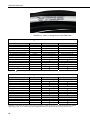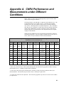
1
CNR4 Net Radiometer
Revision: 11/10
C o p y r i g h t © 2 0 0 0 - 2 0 1 0
C a m p b e l l S c i e n t i f i c , I n c .
Warranty and Assistance
The CNR4 NET RADIOMETER is warranted by Campbell Scientific, Inc. to
be free from defects in materials and workmanship under normal use and
service for twelve (12) months from date of shipment unless specified
otherwise. Batteries have no warranty. Campbell Scientific, Inc.'s obligation
under this warranty is limited to repairing or replacing (at Campbell Scientific,
Inc.'s option) defective products. The customer shall assume all costs of
removing, reinstalling, and shipping defective products to Campbell Scientific,
Inc. Campbell Scientific, Inc. will return such products by surface carrier
prepaid. This warranty shall not apply to any Campbell Scientific, Inc.
products which have been subjected to modification, misuse, neglect, accidents
of nature, or shipping damage. This warranty is in lieu of all other warranties,
expressed or implied, including warranties of merchantability or fitness for a
particular purpose. Campbell Scientific, Inc. is not liable for special, indirect,
incidental, or consequential damages.
Products may not be returned without prior authorization. The following
contact information is for US and International customers residing in countries
served by Campbell Scientific, Inc. directly. Affiliate companies handle
repairs for customers within their territories. Please visit
www.campbellsci.com to determine which Campbell Scientific company
serves your country.
To obtain a Returned Materials Authorization (RMA), contact Campbell
Scientific, Inc., phone (435) 753-2342. After an applications engineer
determines the nature of the problem, an RMA number will be issued. Please
write this number clearly on the outside of the shipping container. Campbell
Scientific's shipping address is:
CAMPBELL SCIENTIFIC, INC.
RMA#_____
815 West 1800 North
Logan, Utah 84321-1784
For all returns, the customer must fill out a “Declaration of Hazardous Material
and Decontamination” form and comply with the requirements specified in it.
The form is available from our website at www.campbellsci.com/repair. A
completed form must be either emailed to [email protected] or faxed to
435-750-9579. Campbell Scientific will not process any returns until we
receive this form. If the form is not received within three days of product
receipt or is incomplete, the product will be returned to the customer at the
customer’s expense. Campbell Scientific reserves the right to refuse service on
products that were exposed to contaminants that may cause health or safety
concerns for our employees.
CNR4 Table of Contents
PDF viewers note: These page numbers refer to the printed version of this document. Use
the Adobe Acrobat® bookmarks tab for links to specific sections.
1. General Description.....................................................1
2. Sensor Specifications .................................................2
2.1
2.2
2.3
2.4
CNR4 Specifications ................................................................................3
Pyranometer Specifications ......................................................................4
Pyrgeometer Specifications ......................................................................5
Optional CNF4 Heater/Ventilator.............................................................5
2.4.1 CNF4 Specifications .......................................................................6
3. Installation....................................................................6
4. Using the Optional CNF4 Heater/Ventilator Unit.......8
5. Using the CNR4 in the Four Separate Components
Mode ...........................................................................9
5.1
5.2
5.3
5.4
5.5
5.6
5.7
Measuring Short-wave Solar Radiation with Pyranometer ......................9
Measuring Long-wave Far Infrared Radiation with Pyrgeometer ............9
Measuring CNR4 Temperature with Thermistor ....................................10
Calculation of Albedo.............................................................................12
Calculation of Net Short-wave Radiation...............................................13
Calculation of Net Long-wave Radiation ...............................................13
Calculation of Net (Total) Radiation ......................................................14
6. Wiring..........................................................................14
7. Datalogger Programming..........................................17
7.1 Sensor Sensitivity ...................................................................................17
7.2 Example Programs..................................................................................17
7.2.1 Example 1, CR1000 Program Using Differential Measurements .17
7.2.2 Example 2, CR3000 Program Using Differential Measurements .21
7.2.3 Example 3, CR5000 Program Using Differential Measurements .24
8. Troubleshooting ........................................................28
8.1
8.2
8.3
8.4
Testing the Pyranometer .........................................................................28
Testing the Pyrgeometer .........................................................................29
Testing the Thermistor............................................................................29
Testing the Pt-100...................................................................................29
i
CNR4 Table of Contents
9. Maintenance and Recalibration ................................29
9.1
9.2
9.3
9.4
Cleaning Windows and Domes.............................................................. 29
Recalibration .......................................................................................... 30
Replacing the Drying Cartridge ............................................................. 30
Replacement Parts.................................................................................. 31
Appendices
A. CNR4 Performance and Measurements under
Different Conditions ............................................. A-1
B. CNF4 Heater/Ventilator ........................................... B-1
B.1
B.2
B.3
B.4
General Information ............................................................................ B-1
Attaching the Optional CNF4 Heater/Ventilator Unit to CNR4 ......... B-3
Wiring ................................................................................................. B-7
Example B, CR3000 Datalogger Program with Heater/Ventilator
Control............................................................................................. B-8
B.5 CNF4 Heater/Ventilator Maintenance............................................... B-11
B.5.1 Testing the Heater.................................................................... B-11
B.5.2 Testing the Ventilator .............................................................. B-11
B.5.3 Replacing the Filter for the Ventilator..................................... B-12
C. CR3000 Program for Measuring Pt-100
Temperature Sensor.............................................C-1
Figures
2-1.
2-2.
3-1.
3-2.
The CNR4 net radiometer with cables and mounting rod, top view ...... 2
The CNR4 net radiometer with CNF 4 heater/ventilator unit, top view. 2
Attaching the mounting rod to the CNR4 body...................................... 7
Attaching the CNR4 onto the mounting rod (CSI p/n 26120) using
vertical pole or horizontal crossarm .................................................... 8
6-1. The CNR4 sensor with SOLAR and TEMP cables .............................. 14
6-2. The marks on the end of the CNR4: S for SOLAR cable, and T for
TEMP cable....................................................................................... 15
6-3. Labels on the pigtail end of the SOLAR cable ..................................... 15
6-4. Labels on the pigtail end of the TEMP cable........................................ 16
9-1. Replacing the Drying Cartridge............................................................ 30
A-1. Different measurement conditions and signals .................................. A-2
A-2. Partly cloudy day for the upward facing pyrgeometer....................... A-2
A-3. Clear day for the downward facing pyrgeometer .............................. A-3
B-1. CNF4 Package Contents .................................................................... B-3
B-2. Attaching the CNF4 to CNR4 using pan-head screws and washers .. B-4
B-3. Making sure the cables are clear from the edges ............................... B-5
B-4. CNF4 solar shield and four flat-head screws ..................................... B-5
B-5. Attaching the solar shield to CNF4 using four flat-head screws........ B-6
B-6. Affixing the sensor label to CNF4 ..................................................... B-6
B-7. Connecting the CNF4 power control cable and the mounting rod..... B-6
ii
CNR4 Table of Contents
Tables
5-1. Resistance values versus CNR4's thermistor temperature in °C ...........11
5-2. Resistance values versus CNR4's Pt-100 temperature in °C .................12
6-1. Datalogger Connections for Differential Measurement ........................16
6-2. Datalogger Connections for Single-ended Measurement......................16
A-1. Typical output signals of CNR4 under different meteorological
conditions. Explanation can be found in the text ........................... A-1
B-1. CR1000 and CR3000 Datalogger Connections for Differential
Measurement with Heater/Ventilator Control..................................B-7
C-1. Datalogger Connections for Differential Measurement with Pt-100 ..C-1
iii
CNR4 Table of Contents
iv
CNR4 Net Radiometer
1. General Description
The CNR4 is a four component net radiometer that measures the energy
balance between incoming and outgoing radiation.
The CNR4 net radiometer consists of a pyranometer pair, one facing upward,
the other facing downward, and a pyrgeometer pair in a similar configuration.
The pyranometer pair measures short-wave solar radiation, and the
pyrgeometer pair measures long-wave far infrared radiation. The upper longwave detector of CNR4 has a meniscus dome. This ensures that water droplets
roll off easily and improves the field of view to nearly 180°, compared with a
150° for a flat window. All four sensors are integrated directly into the
instrument body, instead of separate modules mounted onto the housing. Each
sensor is calibrated individually for optimal accuracy.
Two temperature sensors, a thermistor and a Pt-100, are integrated with the
CNR4 body. The temperature sensor is used to provide information to correct
the infrared readings for the temperature of the instrument housing. Care has
been taken to place the long-wave sensors close to each other and close to the
temperature sensors. This assures that the temperatures of the measurement
surfaces are the same and accurately known. This improves the quality of the
long-wave measurements. Campbell Scientific adds a completion resistor in
the pig tail end of the thermistor cable, so that it is easily interfaced with our
dataloggers for half-bridge measurement.
The CNR4 design is very light in weight and has an integrated solar shield that
reduces thermal effects on both the short-wave and the long-wave
measurements. The cables are made from Santoprene® jacket, which is
intended for outdoor use, and is resistant to a variety of pollutants and UVradiation. The mounting rod can be unscrewed for transport.
An optional ventilation unit with a heater, CNF4, is designed as an extension of
the solar shield and can be fitted new to the CNR4 or retrofitted later. The
heater/ventilation unit is compact and provides efficient air-flow over the
domes and windows to minimize the formation of dew and to reduce the
frequency of cleaning. The integrated heater can be used to melt frost.
The CNR4 specifications when used with CNF4 comply with the WMO
classification of Good Quality.
The CNR4 design is such that both the upward facing and the downwardfacing instruments measure the energy that is received from the whole
hemisphere (180° field of view). The output is expressed in W/m2. The total
spectral range that is measured is roughly from 0.3 to 42 μm. This spectral
range covers both the short-wave solar radiation, 0.3 to 2.8 μm, and the longwave far infrared radiation, 4.5 to 42 μm. The gap between these two produces
negligible errors.
Unlike the CNR1, four probes in the CNR4 have different sensitivity values.
This makes each measurement from four sensors more accurate than when they
are made to have the same sensitivity value with shunt and series resistors.
1
CNR4 Net Radiometer
2. Sensor Specifications
The CNR4 consists of two pyranometers, for measuring short-wave radiation,
and of two pyrgeometers for measuring long-wave radiation. Two temperature
sensors are available as standard, a thermistor and a Pt-100. The optional
heater/ventilator unit CNF4-L is available. See Appendix B for more
information on the CNF4-L.
The properties of the CNR4 are mainly determined by the properties of the
individual probes. Generally the accuracy of the CNR4 will be higher than that
of competitive net-radiometers, because the solar radiation measurement
performed by the pyranometer is accurate, and offers a traceable calibration.
Also the optionally integrated heater/ventilator unit improves the accuracy.
Due to the fact that the net short-wave radiation can be very intense, 1000
W/m2 compared to a typical -100 W/m2 net long-wave radiation, the accuracy
of the short-wave radiation measurement is critical. Wind corrections, as
applied by less accurate competitive instruments are not necessary. The robust
materials used imply that the CNR4 will not suffer damages inflicted by birds.
Figure 2-1 and Figure 2-2 show the CNR4 with and without the CNF4
heater/ventilator. From a spectral point of view, the pyranometer and
pyrgeometer are complementary, and together they cover the full spectral
range.
FIGURE 2-1. The CNR4 net radiometer with cables and mounting rod, top view.
FIGURE 2-2. The CNR4 net radiometer with CNF 4 heater/ventilator unit, top view.
2
CNR4 Net Radiometer
2.1 CNR4 Specifications
Sensor sensitivities:
Four probes have unique sensitivity
values. Please refer to the calibration
sheets or label on the bottom of the
sensor for the sensitivity values.
Operating temperature:
-40 to +80°C (-40 to 176°F)
Operating humidity:
0 to 100 % RH
Bubble level sensitivity:
< 0.5°
Sensor type:
Thermopile
Receiver paint:
Carbon Black
Desiccant:
Silica gel (replaceable)
Housing material:
Anodized aluminum body
Shock/vibration:
IEC 721-3-2-2m2
CE:
Complies with EC guideline
89/336/EEC 73/23/EEC
Environmental protection:
IP 67
Requirements for data acquisition
Radiation components:
4 differential or 4 single-ended analog
channels
Thermistor:
1 voltage excitation and 1 singleended analog channel
Pt-100 temperature:
1 current excitation and 1 differential
analog channel.
Cable length:
User defined
Weight
Sensor:
1.89 lbs (0.85 kg) without cables
Heater/Ventilator, CNF4
(optional):
1.11 lbs (0.50 kg) without cables
Mounting rod:
CNR4 Package includes:
13.67 ” (34.7 cm) length
0.63 ” (1.6 cm) diameter
CNR4 sensor
Mounting rod (1 ea.)
Solar cable (labeled SOLAR)
Temperature cable (labeled TEMP)
Drying cartridges (2 ea.)
WRR Traceable Calibration
Certificate for pyranometers
WRR Traceable Calibration
Certificate for pyrgeometers
Extra Calibration Sticker (to be put on
CNF4, if used)
CNF4 Package includes:
CNF4 Heater/Ventilator
CNF4 cable
3
CNR4 Net Radiometer
2.2 Pyranometer Specifications
* indicates ISO specifications.
Spectral range:
305 to 2800 nm (50% points)
Sensitivity:
10 to 20 µV/W/m2
Response time*:
< 18 seconds (95% response)
Non-linearity*:
< 1% (0-1000 W m-2 irradiance)
Non-stability*:
< 1%
Temperature dependence of
sensitivity*:
< 4% (-10° to +40°C)
Tilt response*:
< 1% at any angle with 1000 W/m2
Directional error*:
< 20 W/m2 at angle up to 80° with
1000 W/m2
Zero offset due to 0 to -200 W/m2
IR net irradiance*:
Zero offset due to temperature
change*:
Operating temperature:
< 15 W/m2
< 3 W/m2 (5K/hr temperature change)
< 1 W/m2 (with CVF 4 installed)
-40°C to +80°C
Field of view
4
Upper detector:
180°
Lower detector:
150° (due to lower solar shield to
prevent illumination at low zenith
angles)
Maximum solar irradiance:
2000 W/m2
Expected accuracy for daily totals:
±10 %
Typical signal output for
atmospheric application:
0 to 15 mV
Impedance:
20 to 200 Ω, typically 50Ω
Detector:
Copper-constantan multi junction
thermopile
Level accuracy:
1 degree
Irradiance:
0 to 2000 W/m2
Spectral selectivity:
< 3% (330-1500 nm spectral interval)
Uncertainty in daily total:
< 5% (95% confidence level)
Instrument calibration:
Indoors. Side by side against reference
CMP3 pyranometer according to ISO
9847:1992 annex A.3.1
CNR4 Net Radiometer
2.3 Pyrgeometer Specifications
Spectral range:
4.5 μm to 42 μm (50% points)
Sensitivity:
5 to 15 μV/W/m2
Impedance:
20 Ω to 200 Ω (typically 50)
Response time:
< 18 seconds (95% response)
Non-linearity:
< 1% (-250 to +250 W/m2 irradiance)
Temperature dependence of
sensitivity:
< 4% (-10° to +40°C)
Tilt error:
Zero offset due to temperature
change:
< 1% (deviation when tilted at any
angle off horizontal)
±4 W/m2 (5K/hr temperature change)
Field of view
Upper
180 degrees
Lower
150 degrees
Net-irradiance:
-250 to +250 W/m2
Non-stability:
< 1% (sensitivity change per year)
Window heating offset:
< 6 W/m2 (1000 W/m2 solar
irradiance)
Uncertainty in daily total:
< 10% (95% confidence level) indoor
calibration
Typical signal output for
atmospheric application:
±5 mV
Temperature sensors
Thermistor:
10k Ω
Pt-100:
DIN class A
Instrument calibration:
Indoors, side by side against reference
CG(R) 3 pyrgeometer. On request
outdoors, side by side against
reference CG(R) 4 pyrgeometer
2.4 Optional CNF4 Heater/Ventilator
The purpose of the heater/ventilator is to prevent dew deposition on the
pyrgeometer and pyrgeometer window, thus enhancing the measurement
accuracy and reliability. Using the heater/ventilator will have negligible effect
on the pyranometer reading.
Generally, the errors caused by the heater/ventilator will be small relative to the
errors that would have been caused by water deposition.
5
CNR4 Net Radiometer
2.4.1 CNF4 Specifications
Heater
Power consumption:
10 W @ 12 Vdc (15 Ω)
Ventilator
Power consumption:
5 W @ 12 Vdc
Supply voltage:
8 to 13.5 Vdc
Weight:
1.11 lbs (0.5 kg)
Operating temperature:
-40 to +80°C
3. Installation
For measurement of net radiation, it is most important that the instrument is
located in a place that is representative of the entire area that one wishes to
study.
When installed on a mast, the preferred orientation should be such that no
shadow is cast on the net radiometer at any time during the day. In the
Northern Hemisphere this implies that the net radiometer should be mounted
on the south side of the mast.
It is suggested that the CNR4 is mounted at a height of at least 1.5 meters
above the surface to avoid shading effects of the instruments on the soil and to
promote spatial averaging of the measurement. If the instrument is h meters
above the surface, 99% of the input of the lower sensors comes from a circular
area with a radius of 10h. Shadows or surface disturbances with radius < 0.1h
will affect the measurement by less than 1%.
It is recommended that the CNR4 be mounted to a separate vertical pipe at
least 25 feet from any other mounting structures. The mounting bracket (CSI
p/n 26120) is used to mount the CNR4 directly to a vertical pipe, or to a
CM20x series Sensor Crossarm. Mount the sensor as follows:
6
1.
First, attach the mounting rod to the CNR4, as shown in Figure 3-1.
2.
Attach mounting bracket (CSI p/n 26120) to the vertical mounting
pipe or CM20x series Sensor Crossarm, using the U-bolts provided
as shown in Figure 3-2.
3.
Insert the mounting rod of the CNR4 sensor into a mounting block of
the mounting bracket (CSI p/n 26120), making sure the sensor points
to the direction of the arrows marked as “SENSOR” on top of the
bracket (see Figure 3-2). Perform a coarse levelling of the sensor
using the bubble level on the top of the CNR4, and tighten the four
screws on top of the mounting bracket to properly secure the
mounting rod so that it does not rotate.
CNR4 Net Radiometer
NOTE
Do not attempt to rotate the instrument using the sensor heads, or
you may damage the sensors; use the mounting rod only.
4.
Perform the fine levelling using the two spring-loaded levelling
screws: one on the front and the other on the back of the bracket.
FIGURE 3-1. Attaching the mounting rod to the CNR4 body.
7
CNR4 Net Radiometer
FIGURE 3-2. Attaching the CNR4 onto the mounting rod
(CSI p/n 26120) using vertical pole or horizontal crossarm.
For installation in buildings or in solar energy applications, one will often have
to mount the CNR4 parallel to the surface that is being studied. This may be in
a tilted or a vertical position. The sensitivity of the radiometers will be
affected, but only in a minor way. This is specified as the so-called tilt effect.
From the specifications one can see that the tilt effect (this is a change in
sensitivity) remains within 1 % (See specifications in Section 2).
4. Using the Optional CNF4 Heater/Ventilator Unit
The optional heater/ventilator unit for CNR4 is available from the
manufacturer. You can purchase the CNF4-L heater/ventilator from Campbell
Scientific with custom cable length. Please refer to the Appendix B for details
on the CNF4 heater/ventilator, including the assembling instructions and
sample programs to control the CNF4 unit.
8
CNR4 Net Radiometer
5. Using the CNR4 in the Four Separate Components
Mode
In the four separate components mode configuration (measuring two shortwave radiation signals, two long-wave signals), all signals are measured
separately. Calculation of net-radiation and albedo can be done on-line by the
datalogger, or off-line by the user during post-processing, using the stored raw
data.
The two pyranometers will measure the short-wave radiation, both incoming
and reflected. The two pyrgeometers will measure the long-wave radiation.
For proper analysis of the pyrgeometer measurement results, they must be
temperature corrected using the temperature measurement performed by the
onboard thermistor or Pt-100 sensor.
The following paragraphs describe how one should treat the instrument, and
how different parameters like albedo, net short-wave radiation, net long-wave
radiation, soil temperature, sky temperature, and net (total) radiation can be
calculated.
5.1 Measuring Short-wave Solar Radiation with Pyranometer
The pyranometer generates an mV signal that is simply proportional to the
incoming short-wave radiation. The conversion factor between voltage, V, and
W/m2 of solar irradiance E, is the so-called calibration constant C (or
sensitivity).
For each pyranometer
E = V/C
(5-1)
Measuring with a pyranometer can be done by connecting two pyranometer
wires to a datalogger. Incidental light results in a positive signal. The
pyranometer mounting plate and ambient air should be at the same
temperature, as much as possible. Conversion of the voltage to irradiance can
be done according to equation 5-1, and this is done inside the datalogger
program.
With the upward-facing pyranometer the so-called global (solar) downwelling
radiation is measured. The downward-facing pyranometer measures the
reflected upwelling solar radiation. When calculating the net radiation, the
upwelling radiation must be subtracted from the downwelling radiation. See
Section 5.5.
5.2 Measuring Long-wave Far Infrared Radiation with
Pyrgeometer
When using the pyrgeometer, you should realize that the signal that is
generated by the pyrgeometer represents the exchange of long-wave far
infrared (thermal) radiation between the pyrgeometer and the object that it is
facing. This implies that the pyrgeometer will generate a positive voltage
output, V, when it faces an object that is hotter than its own sensor housing,
and that it will give a negative voltage signal when it faces an object that is
9
CNR4 Net Radiometer
colder. This means that for estimating the far infrared radiation that is
generated by the object that is faced by the pyrgeometer, usually the sky or the
soil, you will have to take the pyrgeometer temperature, T, into account. This
is why the temperature sensors are incorporated in the CNR4's body near the
pyrgeometer sensing element, and has, therefore, the same temperature as the
pyrgeometer sensor surface. The calculation of the long-wave far infrared
irradiance, E, is done according to the following equation:
For the pyrgeometer only
E = V/C + 5.67·10-8·T4
(5-2)
In this equation C is the sensitivity of the sensor. Please bear in mind that T is
in Kelvin, and not in Celsius or Fahrenheit.
The downward-facing pyrgeometer measures the far infrared radiation that is
emitted by the ground. The upward-facing pyrgeometer measures the far
infrared radiation from the sky. As the sky is typically colder than the
instrument, one can expect negative voltage signals from the upward-facing
pyrgeometer. The Equation 5-2 is used to calculate the far infrared irradiance
of the sky and of the ground.
5.3 Measuring CNR4 Temperature with Thermistor
The CNR4 has two temperature sensors built inside: thermistor and Pt-100.
They both have the identical accuracy. We recommend using the thermistor
with Campbell Scientific dataloggers. The thermistor has a larger resistance
(10 kΩ @ 25°C) than Pt-100 sensor (100 Ω @ 0°C), and the change in
resistance with respect to temperature, in absolute terms, is greater. Therefore,
the cable resistance can be neglected, and the thermistor can easily be
measured using half-bridge measurement instruction on Campbell Scientific
dataloggers. This makes it simpler to program, and uses fewer measurement
channels.
Table 5-1 shows the thermistor resistance values as a function of temperature.
Relatively small errors occur when the CNR4 is not in thermal equilibrium.
This happens for example when the heater is on, or when the sun is shining.
When the heater and ventilator are on, the largest expected deviation between
the real sensor temperature and the thermistor reading is 1 degree. This results
in a worst case error for the pyrgeometer of 5 W/m2. When the sun is shining,
the largest expected deviation between the real sensor temperature and the
thermistor reading is again 1 degree. This results in a worst case error for the
pyrgeometer of 5 W/m2.
The thermistor will not give a good indication of ambient air temperature; at
1000 W/m2 solar radiation, and no wind, the instrument temperature will rise
approximately 5 degrees above the ambient temperature.
The offsets of both the pyranometers and the pyrgeometers might be larger
than 5W/m2 if large temperature gradients are forced on the instrument (larger
than 5 K/hr). This happens for example when rain hits the instrument. The
occurrence of this can be detected using the thermistor readout, and can be
used for data filtering.
10
CNR4 Net Radiometer
The thermistor measurement can be done by the datalogger, using the half
bridge measurement method which requires one voltage excitation and one
single-ended analog channel.
Alternatively, you can use the Pt-100 to make the temperature measurement.
In order to make the temperature measurement, using the Pt-100 sensor, you
will need one current excitation channel, and one differential analog channel.
Please refer to Appendix C for a sample program to measure Pt-100.
TABLE 5-1. Resistance values versus CNR4's thermistor temperature in °C.
Temperature
[°C]
Resistance
[Ω]
Temperature
[°C]
Resistance
[Ω]
Temperature
[°C]
Resistance
[Ω]
-30
-29
-28
-27
-26
-25
-24
-23
-22
-21
-20
-19
-18
-17
-16
-15
-14
-13
-12
-11
-10
-9
-8
-7
-6
-5
-4
-3
-2
-1
135200
127900
121100
114600
108600
102900
97490
92430
87660
83160
78910
74910
71130
67570
64200
61020
58010
55170
52480
49940
47540
45270
43110
41070
39140
37310
35570
33930
32370
30890
0
1
2
3
4
5
6
7
8
9
10
11
12
13
14
15
16
17
18
19
20
21
22
23
24
25
26
27
28
29
29490
28150
26890
25690
24550
23460
22430
21450
20520
19630
18790
17980
17220
16490
15790
15130
14500
13900
13330
12790
12260
11770
11290
10840
10410
10000
9605
9227
8867
8523
30
31
32
33
34
35
36
37
38
39
40
41
42
43
44
45
46
47
48
49
50
51
52
53
54
55
56
57
58
59
8194
7880
7579
7291
7016
6752
6500
6258
6026
5805
5592
5389
5193
5006
4827
4655
4489
4331
4179
4033
3893
3758
3629
3504
3385
3270
3160
3054
2952
2854
11
CNR4 Net Radiometer
TABLE 5-2. Resistance values versus CNR4's Pt-100 temperature in °C.
Temperature
[°C]
-30
-29
-28
-27
-26
-25
-24
-23
-22
-21
-20
-19
-18
-17
-16
-15
-14
-13
-12
-11
-10
-9
-8
-7
-6
-5
-4
-3
-2
-1
Resistance
[Ω]
88.22
88.62
89.01
89.40
89.80
90.19
90.59
90.98
91.37
91.77
92.16
92.55
92.95
93.34
93.73
94.12
94.52
94.91
95.30
95.69
96.09
96.48
96.87
97.26
97.65
98.04
98.44
98.83
99.22
99.61
Temperature
[°C]
0
1
2
3
4
5
6
7
8
9
10
11
12
13
14
15
16
17
18
19
20
21
22
23
24
25
26
27
28
29
Resistance
[Ω]
100.00
100.39
100.78
101.17
101.56
101.95
102.34
102.73
103.12
103.51
103.90
104.29
104.68
105.07
105.46
105.85
106.24
106.63
107.02
107.40
107.79
108.18
108.57
108.96
109.35
109.73
110.12
110.51
110.90
111.28
Temperature
[°C]
30
31
32
33
34
35
36
37
38
39
40
41
42
43
44
45
46
47
48
49
50
51
52
53
54
55
56
57
58
59
Resistance
[Ω]
111.67
112.06
112.45
112.83
113.22
113.61
113.99
114.38
114.77
115.15
115.54
115.93
116.31
116.70
117.08
117.47
117.85
118.24
118.62
119.01
119.40
119.78
120.16
120.55
120.93
121.32
121.70
122.09
122.47
122.86
5.4 Calculation of Albedo
Albedo is the ratio of reflected short-wave radiation to incoming short-wave
radiation. This unitless value ranges between 0 and 1. Typical values are 0.9
for snow, and 0.3 for grassland. To determine the albedo, the measured values
of the two pyranometers can be used. The pyrgeometers are not involved, as
they do not measure short-wave solar radiation. Do not use the measured
values when the solar elevation is lower than 10 degrees above the horizon.
Errors in the measurements at these elevations are likely and yield unreliable
results. This is due to deviations in the directional response of the
pyranometers.
Albedo = (E lower Pyranometer) / (E upper Pyranometer)
12
(5-3)
CNR4 Net Radiometer
In the equation above, E is calculated according to the Equation 5-1.
Albedo will always be smaller than 1. Checking this can be used as a tool for
quality assurance of your data. If you know the approximate albedo at your
site, the calculation of albedo can also serve as a tool for quality control of your
measured data at a specific site.
5.5 Calculation of Net Short-wave Radiation
The net short-wave solar radiation is equal to the incoming (downwelling)
short-wave radiation minus the reflected (upwelling) short-wave radiation.
Net Short-wave Radiation = (E upper Pyranometer) - (E lower Pyranometer) (5-4)
In the equation above, E is calculated according to Equation 5-1.
Net short-wave solar radiation will always be positive. This can be used as a
tool for quality assurance of your measured data.
5.6 Calculation of Net Long-wave Radiation
The net long-wave far Infrared radiation is the part that contributes to heating
or cooling of the earth's surface. In practice, usually the net long-wave far
infrared radiation will be negative.
Net Long-wave Radiation = (E upper Pyrgeometer) - (E lower Pyrgeometer) (5-5)
In the equation above, E is calculated according to Equation 5-2. According to
equation 5-5 above, the terms that contain the sensor body temperature T
cancel each other. Therefore, if one is only interested in the net long-wave
radiation, instead of separate upper and lower components of the long-wave
radiation, the CNR4 temperature measurement is not required.
The E measured with the pyrgeometer actually represents the irradiance of the
sky (for upward- facing pyrgeometer) or the ground (for downward-facing
pyrgeometer). Assuming that these two, ground and sky, behave like perfect
blackbodies, theoretically, one can calculate an effective "Sky temperature"
and an effective "Ground temperature".
⎡ E upper Pyrgeometer ⎤
Sky temperature = ⎢
⎥
5.67 ⋅ 10 −8
⎣
⎦
1/ 4
⎡ E lower Pyrgeometer ⎤
Ground Temperature = ⎢
⎥
5.67 ⋅ 10 −8
⎣
⎦
(5-6)
1/ 4
(5-7)
As a rule of thumb, for ambient temperatures of about 20 degrees Celsius, one
can say that one degree of temperature difference between two objects results
in a 5 W/m2 exchange of radiative energy (infinite objects):
1 degree of temperature difference = 5 W/m2 (rule of thumb)
13
CNR4 Net Radiometer
5.7 Calculation of Net (Total) Radiation
In the four separate components mode, net radiation, Rn, can be calculated
using the individual sensor measurement results:
Rn = {(E upper Pyranometer) - (E lower Pyranometer)}
+ {(E upper Pyrgeometer) - (E lower Pyrgeometer)}
(5-8)
Where E upper/lower pyranometers are calculated according to Equation 5-1,
and E upper/lower pyrgeometers are calculated according to Equation 5-2. The
terms with T cancel each other out.
6. Wiring
The CNR4 has two outputs for short-wave radiation, two outputs for long-wave
radiation, thermistor output, and Pt-100 temperature sensor output. In addition,
if a user chooses to attach the optional CNF4 heater/ventilator unit, it will have
power wires for heater and ventilator. All wiring schemes shown in this
manual and the sample programs will use the thermistor for the temperature
measurement of the CNR4. The wiring diagrams for the thermistor in this
manual is applicable only if the CNR4 and the cables were purchased from
Campbell Scientific, Inc.
The CNR4 comes with two sets of cables labelled SOLAR and TEMP, as
shown in Figure 6-1. Figure 6-2 shows the marks by the connecting ports at
the sensor’s end for the cable connection: S and T for SOLAR and TEMP
cables, respectively. The two cables, SOLAR and TEMP, have identical
connectors, and care should be used to make sure that the correct cables are
connected to the correct ports of the sensor.
FIGURE 6-1. The CNR4 sensor with SOLAR and TEMP cables.
14
CNR4 Net Radiometer
FIGURE 6-2. The marks on the end of the CNR4: S for SOLAR cable,
and T for TEMP cable.
The measurement details for Pt-100 sensor, including the wiring diagram and
sample program are explained in the Appendix C of this manual.
The four radiation outputs can be measured using differential or single-ended
inputs on the datalogger. A differential voltage measurement is recommended
because it has better noise rejection than a single-ended measurement.
NOTE
When differential inputs are used, jumper the low side of the
input to AG or
to keep the signal in common mode range.
The Tables 6-1 and 6-2 show the wiring instructions for the differential
measurement and single-ended measurement connections to the datalogger,
respectively. The cables have the white band at the pigtail end of the cable
with the color keys. See the Figure 6-3 and 6-4 below for the labels on the
cable for both the SOLAR and TEMP cables.
FIGURE 6-3. Labels on the pigtail end of the SOLAR cable.
15
CNR4 Net Radiometer
FIGURE 6-4. Labels on the pigtail end of the TEMP cable.
TABLE 6-1. Datalogger Connections for Differential Measurement
Function
Pyranometer Up Signal
Pyranometer Up Reference
Pyranometer Down Signal
Pyranometer Down Reference
Pyrgeometer Up Signal
Pyrgeometer Up Reference
Pyrgeometer Down Signal
Pyrgeometer Down Reference
Shield
Wire Color
Red
*Blue
White
*Black
Grey
*Yellow
Brown
*Green
Clear
CR1000
Differential Input (H)
Differential Input (L)
Differential Input (H)
Differential Input (L)
Differential Input (H)
Differential Input (L)
Differential Input (H)
Differential Input (L)
CR3000/CR5000
Differential Input (H)
Differential Input (L)
Differential Input (H)
Differential Input (L)
Differential Input (H)
Differential Input (L)
Differential Input (H)
Differential Input (L)
Thermistor Signal
Thermistor Voltage Excitation
Thermistor Signal Reference
Shield
White
Red
Black
Clear
Single-ended Input
Voltage Excitation (VX)
Single-ended Input
Voltage Excitation (VX)
*Jumper to
with user supplied wire.
TABLE 6-2. Datalogger Connections for Single-ended Measurement
Function
Pyranometer Up Signal
Pyranometer Up Reference
Pyranometer Down Signal
Pyranometer Down Reference
Pyrgeometer Up Signal
Pyrgeometer Up Reference
Pyrgeometer Down Signal
Pyrgeometer Down Reference
Shield
Wire Color
Red
Blue
White
Black
Grey
Yellow
Brown
Green
Clear
Thermistor Signal
Thermistor Voltage Excitation
Thermistor Signal Reference
Shield
White
Red
Black
Clear
CR1000
Single-Ended Input
CR3000/CR5000
Single-Ended Input
Single-Ended Input
Single-Ended Input
Single-Ended Input
Single-Ended Input
Single-Ended Input
Single-Ended Input
Single-ended Input
Voltage Excitation (VX)
Single-ended Input
Voltage Excitation (VX)
*Pull back wires for Pt-100 (grey, brown, green, and yellow), which are not in use, and tie them around the TEMP
cable using a cable tie or electrical tape to avoid possible damage to the Pt-100, due to electrical short circuit.
16
CNR4 Net Radiometer
7. Datalogger Programming
The CNR4 outputs four voltages that typically range from 0 to 15 mV for the
pyranometers, and ± 5 mV for the pyrgeometers. A differential voltage
measurement is recommended because it has better noise rejection than a
single-ended measurement. If differential channels are not available, singleended measurements can be used. The acceptability of a single-ended
measurement can be determined by simply comparing the results of singleended and differential measurements made under the same conditions.
Additionally, one voltage excitation channel and one single-ended analog
channel are required to make the temperature measurement of the sensor body,
using the thermistor.
7.1 Sensor Sensitivity
Unlike the CNR1, the CNR4 comes with four different sensor sensitivity
values for four separate probes. The CNR4 sensor comes with two copies of
‘Certificate of Calibration’ by the manufacturer. They show the sensor serial
number and sensitivity values for four individual probes: one copy for
pyranometers, and another copy for pyrgeometers. The serial number and
sensitivity values are also shown on a label affixed to the bottom of the sensor.
If you choose to attach the CNF4, heater/ventilator unit to the CNR4, this label
showing the serial number and sensitivity values will be covered. After
attaching the CNF4 heater/ventilator, make sure to affix the extra label to the
bottom of the CNF4, heater/ventilator unit so that you will have the label on a
visible location. The extra label containing the serial number and sensitivity
values is supplied with the purchase of the CNR4. Please refer to the
Appendix B for more details.
The sensor sensitivity is in the units of μV/(W/m2). This needs to be converted
into the units of (W/m2)/mV to be used as a multiplier parameter inside the
datalogger program. To convert the units, divide the sensor sensitivity value
into 1000. For example, if the sensitivity is 7.30 μV/(W/m2), the multiplier is
1000/7.3 = 136.99 (W/m2)/mV.
7.2 Example Programs
7.2.1 Example 1, CR1000 Program Using Differential Measurements
The Program Example 1 requires four differential channels to measure the four
radiation outputs and one excitation channel and one single-ended channel to
measure the thermistor. The program measures the sensors every 1 second,
performs the on-line processing of the data and stores the following processed
data to a data table called cnr4_data once every 60 minutes. It also stores the
raw time-series data from CNR4 to data table called cnr4_ts.
Minimum Battery voltage
Sample Datalogger panel temperature
Average Short-wave radiation (pyranometer up)
Average Short-wave radiation (pyranometer down)
Average Long-wave radiation (pyrgeometer up)
Average Long-wave radiation (pyrgeometer down)
Average CNR4 thermistor temperature (degrees C)
Average CNR4 thermistor temperature (Kelvin)
17
CNR4 Net Radiometer
Average Corrected long-wave radiation (pyrgeometer up)
Average Corrected long-wave radiation (pyrgeometer down)
Average Short-wave net radiation
Average Long-wave net radiation
Average Albedo
Average Net radiation
'CR1000 Series Datalogger
'
'CNR4 program
'This program measures CNR4 four-component net radiometer
'This program also measures the thermistor inside the CNR4
'
'User must enter the sensitivity values for all four probes in the program and save/compile
'prior to downloading it to the datalogger.
'Search for the text string "unique" to find places to enter the sensitivity values.
'
'Wiring Instructions
'
'ANALOG CHANNELS
'1H CNR4 Pyranometer Upper signal (red)
'1L CNR4 Pyranometer Upper signal reference (blue)
'gnd jumper to 1L
'
'2H CNR4 Pyranometer Lower signal (white)
'2L CNR4 Pyranometer Lower signal reference (black)
'gnd jumper to 2L
'
'3H CNR4 Pyrgeometer Upper signal (grey)
'3L CNR4 Pyrgeometer Upper signal reference (yellow)
'gnd jumper to 3L
'
'4H CNR4 Pyrgeometer Lower signal (brown)
'4L CNR4 Pyrgeometer Lower signal reference (green)
'gnd jumper to 4L
'
CNR4 shield (clear)
'
'
'
'8H
'8L CNR4 thermistor signal (white)
'gnd CNR4 thermistor signal reference (black)
'
CNR4 thermistor shield (clear)
'
'VOLTAGE EXCITATION
'
'EX2
CNR4 thermistor voltage excitation (red)
'
'CNR4 sensor
Public logger_temp, batt_volt
Public cnr4(4)
Alias cnr4(1) = short_up
Alias cnr4(2) = short_dn
Alias cnr4(3) = long_up
Alias cnr4(4) = long_dn
18
CNR4 Net Radiometer
Public cnr4_T_C
Public cnr4_T_K
Public long_up_corr
Public long_dn_corr
Public Rs_net
Public Rl_net
Public albedo
Public Rn
'CNR4 thermistor temperature in Celcius
'CNR4 thermistor temperature in Kelvin
'Downwelling long-wave radiation with temperature correction
'Upwelling long-wave radiation with temperature correction
'short-wave net radiation
'long-wave net radiation
'Albedo
'total net radiation
Units logger_temp = degC
Units batt_volt = volts
Units short_up = W/m^2
Units short_dn = W/m^2
Units long_up = W/m^2
Units long_dn = W/m^2
Units cnr4_T_C = deg_C
Units cnr4_T_K = K
Units long_up_corr = W/m^2
Units long_dn_corr = W/m^2
Units Rs_net = W/m^2
Units Rl_net = W/m^2
Units albedo = W/m^2
Units Rn = W/m^2
Dim Rs, Vs_Vx
'CNR4 sensitivities: refer to the Certificate of Calibration from Kipp & Zonen for sensitivity values
'for each probes, and enter them below.
Const pyranometer_up_sensitivity = 15.35
'unique sensitivity for upper pyranometer
'(microV/W/m^2)
Const pyranometer_dn_sensitivity = 15.41
'unique sensitivity for lower pyranometer
'(microV/W/m^2)
Const pyrgeometer_up_sensitivity = 8.50
'unique sensitivity for upper pyrgeometer
'(microV/W/m^2)
Const pyrgeometer_dn_sensitivity = 7.09
'unique sensitivity for lower pyrgeometer
'(microV/W/m^2)
'CNR4 multipliers
Public cnr4_mult(4)
Const pyranometer_up_mult = 1000/pyranometer_up_sensitivity
Const pyranometer_dn_mult = 1000/pyranometer_dn_sensitivity
Const pyrgeometer_up_mult = 1000/pyrgeometer_up_sensitivity
Const pyrgeometer_dn_mult = 1000/pyrgeometer_dn_sensitivity
'(W/m^2/mV)
'(W/m^2/mV)
'(W/m^2/mV)
'(W/m^2/mV)
DataTable (cnr4_data,True,-1)
DataInterval (0,60,Min,10)
CardOut (1,-1)
Minimum (1,batt_volt,FP2,0,False)
Sample (1,logger_temp,FP2)
Average (4,cnr4(1),IEEE4,False)
Average (1,cnr4_T_C,IEEE4,False)
Average (1,cnr4_T_K,IEEE4,False)
Average (1,long_up_corr,IEEE4,False)
Average (1,long_dn_corr,IEEE4,False)
Average (1,Rs_net,IEEE4,False)
19
CNR4 Net Radiometer
Average (1,Rl_net,IEEE4,False)
Average (1,albedo,IEEE4,False)
Average (1,Rn,IEEE4,False)
EndTable
DataTable (cnr4_ts,True,-1)
DataInterval (0,1,Sec,10)
CardOut (1,-1)
Sample (4,cnr4(1),IEEE4)
Sample (1,cnr4_T_K,IEEE4)
EndTable
BeginProg
'Load the multiplier values for the CNR4
cnr4_mult(1) = pyranometer_up_mult
cnr4_mult(2) = pyranometer_dn_mult
cnr4_mult(3) = pyrgeometer_up_mult
cnr4_mult(4) = pyrgeometer_dn_mult
Scan (1,Sec,3,0)
PanelTemp (logger_temp,250)
Battery (batt_volt)
'CNR4 radiation measurements
VoltDiff (cnr4(1),4,mV25C,1,True ,0,_60Hz,cnr4_mult(1),0)
'CNR4 thermistor measurement
BrHalf (Vs_Vx,1,mV2500,16,Vx2,1,2500,True ,0,250,1.0,0)
Rs = 1000*(Vs_Vx/(1-Vs_Vx))
cnr4_T_C = 1/(1.0295e-3+2.391e-4*LN(Rs)+1.568e-7*(LN(Rs))^3)-273.15
'Convert CNR4 temperature to Kelvin
cnr4_T_K = cnr4_T_C+273.15
'Correct the long-wave radiation values from pyrgeometers
long_up_corr = long_up+5.67e-8*cnr4_T_K^4
long_dn_corr = long_dn+5.67e-8*cnr4_T_K^4
'Compute short-wave net radiation
Rs_net = short_up - short_dn
'Compute long-wave net radiation
Rl_net = long_up - long_dn
'Compute albedo
albedo = short_dn/short_up
'Compute net radiation
Rn = Rs_net + Rl_net
CallTable cnr4_data
CallTable cnr4_ts
NextScan
EndProg
20
CNR4 Net Radiometer
7.2.2 Example 2, CR3000 Program Using Differential Measurements
The Program Example 2 requires four differential channels to measure the four
radiation outputs and one excitation channel and one single-ended channel to
measure the thermistor. The program measures the sensors every 1 second,
performs the on-line processing of the data and stores the following processed
data to a data table called cnr4_data once every 60 minutes. It also stores the
raw time-series data from CNR4 to data table called cnr4_ts.
Minimum Battery voltage
Sample Datalogger panel temperature
Average Short-wave radiation (pyranometer up)
Average Short-wave radiation (pyranometer down)
Average Long-wave radiation (pyrgeometer up)
Average Long-wave radiation (pyrgeometer down)
Average CNR4 thermistor temperature (degrees C)
Average CNR4 thermistor temperature (Kelvin)
Average Corrected long-wave radiation (pyrgeometer up)
Average Corrected long-wave radiation (pyrgeometer down)
Average Short-wave net radiation
Average Long-wave net radiation
Average Albedo
Average Net radiation
'CR3000 Series Datalogger
'
'CNR4 program
'This program measures CNR4 four-component net radiometer
'This program also measures the thermistor inside the CNR4
'
'User must enter the sensitivity values for all four probes in the program and save/compile
'prior to downloading it to the datalogger.
'Search for the text string "unique" to find places to enter the sensitivity values.
'
'Wiring Instructions
'
'ANALOG CHANNELS
'1H CNR4 Pyranometer Upper signal (red)
'1L CNR4 Pyranometer Upper signal reference (blue)
'gnd jumper to 1L
'
'2H CNR4 Pyranometer Lower signal (white)
'2L CNR4 Pyranometer Lower signal reference (black)
'gnd jumnper to 2L
'
'3H CNR4 Pyrgeometer Upper signal (grey)
'3L CNR4 Pyrgeometer Upper signal reference (yellow)
'gnd jumper to 3L
'
'4H CNR4 Pyrgeometer Lower signal (brown)
'4L CNR4 Pyrgeometer Lower signal reference (green)
'gnd jumper to 4L
'
CNR4 shield (clear)
'
'
21
CNR4 Net Radiometer
'8H
'8L CNR4 thermistor signal (white)
'gnd CNR4 thermistor signal reference (black)
'
CNR4 thermistor shield (clear)
'
'VOLTAGE EXCITATION
'
'VX1
CNR4 thermistor voltage excitation (red)
'
'CNR4 sensor
Public logger_temp, batt_volt
Public cnr4(4)
Alias cnr4(1) = short_up
Alias cnr4(2) = short_dn
Alias cnr4(3) = long_up
Alias cnr4(4) = long_dn
Public cnr4_T_C
Public cnr4_T_K
Public long_up_corr
Public long_dn_corr
Public Rs_net
Public Rl_net
Public albedo
Public Rn
'CNR4 thermistor temperature in Celcius
'CNR4 thermistor temperature in Kelvin
'Downwelling long-wave radiation with temperature correction
'Upwelling long-wave radiation with temperature correction
'short-wave net radiation
'long-wave net radiation
'Albedo
'total net radiation
Units logger_temp = degC
Units batt_volt = volts
Units short_up = W/m^2
Units short_dn = W/m^2
Units long_up = W/m^2
Units long_dn = W/m^2
Units cnr4_T_C = deg_C
Units cnr4_T_K = K
Units long_up_corr = W/m^2
Units long_dn_corr = W/m^2
Units Rs_net = W/m^2
Units Rl_net = W/m^2
Units albedo = W/m^2
Units Rn = W/m^2
Dim Rs, Vs_Vx
'CNR4 sensitivities: refer to the Certificate of Calibration from Kipp & Zonen for sensitivity values
'for each probes, and enter them below.
Const pyranometer_up_sensitivity = 15.35
'unique sensitivity for upper pyranometer
'(microV/W/m^2)
Const pyranometer_dn_sensitivity = 15.41
'unique sensitivity for lower pyranometer
'(microV/W/m^2)
Const pyrgeometer_up_sensitivity = 8.50
'unique sensitivity for upper pyrgeometer
'(microV/W/m^2)
Const pyrgeometer_dn_sensitivity = 7.09
'unique sensitivity for lower pyrgeometer
'(microV/W/m^2)
22
CNR4 Net Radiometer
'CNR4 multipliers
Public cnr4_mult(4)
Const pyranometer_up_mult = 1000/pyranometer_up_sensitivity
Const pyranometer_dn_mult = 1000/pyranometer_dn_sensitivity
Const pyrgeometer_up_mult = 1000/pyrgeometer_up_sensitivity
Const pyrgeometer_dn_mult = 1000/pyrgeometer_dn_sensitivity
'(W/m^2/mV)
'(W/m^2/mV)
'(W/m^2/mV)
'(W/m^2/mV)
DataTable (cnr4_data,True,-1)
DataInterval (0,60,Min,10)
CardOut (1,-1)
Minimum (1,batt_volt,FP2,0,False)
Sample (1,logger_temp,FP2)
Average (4,cnr4(1),IEEE4,False)
Average (1,cnr4_T_C,IEEE4,False)
Average (1,cnr4_T_K,IEEE4,False)
Average (1,long_up_corr,IEEE4,False)
Average (1,long_dn_corr,IEEE4,False)
Average (1,Rs_net,IEEE4,False)
Average (1,Rl_net,IEEE4,False)
Average (1,albedo,IEEE4,False)
Average (1,Rn,IEEE4,False)
EndTable
DataTable (cnr4_ts,True,-1)
DataInterval (0,1,Sec,10)
CardOut (1,-1)
Sample (4,cnr4(1),IEEE4)
Sample (1,cnr4_T_K,IEEE4)
EndTable
BeginProg
'Load the multiplier values for the CNR4
cnr4_mult(1) = pyranometer_up_mult
cnr4_mult(2) = pyranometer_dn_mult
cnr4_mult(3) = pyrgeometer_up_mult
cnr4_mult(4) = pyrgeometer_dn_mult
Scan (1,Sec,3,0)
PanelTemp (logger_temp,250)
Battery (batt_volt)
'CNR4 radiation measurements
VoltDiff (cnr4(1),4,mV20C,1,True ,0,_60Hz,cnr4_mult(1),0)
'CNR4 thermistor measurement
BrHalf (Vs_Vx,1,mv5000,16,Vx1,1,2500,True ,0,250,1.0,0)
Rs = 1000*(Vs_Vx/(1-Vs_Vx))
cnr4_T_C = 1/(1.0295e-3+2.391e-4*LN(Rs)+1.568e-7*(LN(Rs))^3)-273.15
'Convert CNR4 temperature to Kelvin
cnr4_T_K = cnr4_T_C+273.15
'Correct the long-wave radiation values from pyrgeometers
long_up_corr = long_up+5.67e-8*cnr4_T_K^4
long_dn_corr = long_dn+5.67e-8*cnr4_T_K^4
23
CNR4 Net Radiometer
'Compute short-wave net radiation
Rs_net = short_up - short_dn
'Compute long-wave net radiation
Rl_net = long_up - long_dn
'Compute albedo
albedo = short_dn/short_up
'Compute net radiation
Rn = Rs_net + Rl_net
CallTable cnr4_data
CallTable cnr4_ts
NextScan
EndProg
7.2.3 Example 3, CR5000 Program Using Differential Measurements
The Program Example 3 requires four differential channels to measure the four
radiation outputs and one excitation channel and one single-ended channel to
measure the thermistor. The program measures the sensors every 1 second,
performs the on-line processing of the data and stores the following processed
data to a data table called cnr4_data once every 60 minutes. It also stores the
raw time-series data from CNR4 to data table called cnr4_ts.
NOTE
The variables for the CR5000 datalogger can be up to 16
characters in length. However, if the variable is processed in the
output table by an output type other than Sample, the name will
be truncated in the datalogger to 12 characters, plus an
underscore and a 3 digit suffix indicating the output type (e.g.
_avg, _max).
Minimum Battery voltage
Sample Datalogger panel temperature
Average Short-wave radiation (pyranometer up)
Average Short-wave radiation (pyranometer down)
Average Long-wave radiation (pyrgeometer up)
Average Long-wave radiation (pyrgeometer down)
Average CNR4 thermistor temperature (degrees C)
Average CNR4 thermistor temperature (Kelvin)
Average Corrected long-wave radiation (pyrgeometer up)
Average Corrected long-wave radiation (pyrgeometer down)
Average Short-wave net radiation
Average Long-wave net radiation
Average Albedo
Average Net radiation
24
CNR4 Net Radiometer
'CR5000 Series Datalogger
'
'CNR4 program
'This program measures CNR4 four-component net radiometer
'This program also measures the thermistor inside the CNR4
'
'User must enter the sensitivity values for all four probes in the program and save/compile
'prior to downloading it to the datalogger.
'Search for the text string "unique" to find places to enter the sensitivity values.
'
'Wiring Instructions
'
'ANALOG CHANNELS
'1H CNR4 Pyranometer Upper signal (red)
'1L CNR4 Pyranometer Upper signal reference (blue)
'gnd jumper to 1L
'
'2H CNR4 Pyranometer Lower signal (white)
'2L CNR4 Pyranometer Lower signal reference (black)
'gnd jumnper to 2L
'
'3H CNR4 Pyrgeometer Upper signal (grey)
'3L CNR4 Pyrgeometer Upper signal reference (yellow)
'gnd jumper to 3L
'
'4H CNR4 Pyrgeometer Lower signal (brown)
'4L CNR4 Pyrgeometer Lower signal reference (green)
'gnd jumper to 4L
'
CNR4 shield (clear)
'
'
'8H
'8L CNR4 thermistor signal (white)
'gnd CNR4 thermistor signal reference (black)
'
CNR4 thermistor shield (clear)
'
'VOLTAGE EXCITATION
'
'VX1
CNR4 thermistor voltage excitation (red)
'
'CNR4 sensor
Public logger_temp, batt_volt
Public cnr4(4)
Alias cnr4(1) = short_up
Alias cnr4(2) = short_dn
Alias cnr4(3) = long_up
Alias cnr4(4) = long_dn
Public cnr4_T_C
Public cnr4_T_K
Public long_up_corr
Public long_dn_corr
Public Rs_net
'CNR4 thermistor temperature in Celcius
'CNR4 thermistor temperature in Kelvin
'Downwelling long-wave radiation with temperature correction
'Upwelling long-wave radiation with temperature correction
'short-wave net radiation
25
CNR4 Net Radiometer
Public Rl_net
Public albedo
Public Rn
'long-wave net radiation
'Albedo
'total net radiation
Units logger_temp = degC
Units batt_volt = volts
Units short_up = W/m^2
Units short_dn = W/m^2
Units long_up = W/m^2
Units long_dn = W/m^2
Units cnr4_T_C = deg_C
Units cnr4_T_K = K
Units long_up_corr = W/m^2
Units long_dn_corr = W/m^2
Units Rs_net = W/m^2
Units Rl_net = W/m^2
Units albedo = W/m^2
Units Rn = W/m^2
Dim Rs, Vs_Vx
'CNR4 sensitivities: refer to the Certificate of Calibration from Kipp & Zonen for sensitivity values
'for each probes, and enter them below.
Const pyra_up_sensitiv = 15.35
'unique sensitivity for upper pyranometer (microV/W/m^2)
Const pyra_dn_sensitiv = 15.41
'unique sensitivity for lower pyranometer (microV/W/m^2)
Const pyrg_up_sensitiv = 8.50
'unique sensitivity for upper pyrgeometer (microV/W/m^2)
Const pyrg_dn_sensitiv = 7.09
'unique sensitivity for lower pyrgeometer (microV/W/m^2)
'CNR4 multipliers
Public cnr4_mult(4)
Const pyra_up_mult = 1000/pyra_up_sensitiv
Const pyra_dn_mult = 1000/pyra_dn_sensitiv
Const pyrg_up_mult = 1000/pyrg_up_sensitiv
Const pyrg_dn_mult = 1000/pyrg_dn_sensitiv
DataTable (cnr4_dat,True,-1)
DataInterval (0,60,Min,10)
CardOut (1,-1)
Minimum (1,batt_volt,FP2,0,False)
Sample (1,logger_temp,FP2)
Average (4,cnr4(1),IEEE4,False)
Average (1,cnr4_T_C,IEEE4,False)
Average (1,cnr4_T_K,IEEE4,False)
Average (1,long_up_corr,IEEE4,False)
Average (1,long_dn_corr,IEEE4,False)
Average (1,Rs_net,IEEE4,False)
Average (1,Rl_net,IEEE4,False)
Average (1,albedo,IEEE4,False)
Average (1,Rn,IEEE4,False)
EndTable
26
'(W/m^2/mV)
'(W/m^2/mV)
'(W/m^2/mV)
'(W/m^2/mV)
CNR4 Net Radiometer
DataTable (cnr4_ts,True,-1)
DataInterval (0,1,Sec,10)
CardOut (1,-1)
Sample (4,cnr4(1),IEEE4)
Sample (1,cnr4_T_K,IEEE4)
EndTable
BeginProg
'Load the multiplier values for the CNR4
cnr4_mult(1) = pyra_up_mult
cnr4_mult(2) = pyra_dn_mult
cnr4_mult(3) = pyrg_up_mult
cnr4_mult(4) = pyrg_dn_mult
Scan (1,Sec,3,0)
PanelTemp (logger_temp,250)
Battery (batt_volt)
'CNR4 radiation measurements
VoltDiff (cnr4(1),4,mV20C,1,True ,0,_60Hz,cnr4_mult(1),0)
'CNR4 thermistor measurement
BrHalf (Vs_Vx,1,mv5000,21,Vx1,1,2500,True ,0,250,1.0,0)
Rs = 1000*(Vs_Vx/(1-Vs_Vx))
cnr4_T_C = 1/(1.0295e-3+2.391e-4*LN(Rs)+1.568e-7*(LN(Rs))^3)-273.15
'Convert CNR4 temperature to Kelvin
cnr4_T_K = cnr4_T_C+273.15
'Correct the long-wave radiation values from pyrgeometers
long_up_corr = long_up+5.67e-8*cnr4_T_K^4
long_dn_corr = long_dn+5.67e-8*cnr4_T_K^4
'Compute short-wave net radiation
Rs_net = short_up - short_dn
'Compute long-wave net radiation
Rl_net = long_up - long_dn
'Compute albedo
albedo = short_dn/short_up
'Compute net radiation
Rn = Rs_net + Rl_net
CallTable cnr4_dat
CallTable cnr4_ts
NextScan
EndProg
27
CNR4 Net Radiometer
8. Troubleshooting
If there is no indication as to what may be the problem, start performing the
following "upside-down test", which is a rough test for a first diagnosis. It can
be performed both outdoors and indoors. Indoors, a lamp can be used as a
source for both short-wave and long-wave radiation. Outdoors, one should
preferably work with a solar elevation of more than 45 degrees (45 degrees
above horizon) and under stable conditions (no large changes in solar
irradiance, and preferably no clouds).
1.
Measure the radiation outputs in the normal position. Record the
measured values when the signals have stabilized, i.e. after about three
minutes.
2.
Rotate the instrument 180 degrees, so that the upper and the lower sensors
are now in the reverse orientation as to the previous position.
3.
Measure the radiation outputs once more. Record the measured values
when the radiometers have stabilized.
4.
The computed net radiation values in rotated position should be equal in
magnitude but only differing in sign. In a rough test like this, deviations
of ± 10 % can be tolerated. If deviations greater than this are encountered,
the following tests might help.
8.1 Testing the Pyranometer
As a first test, check the sensor impedance. It should have a nominal value as
indicated in the specifications. Zero, or infinite resistance, indicates a failure in
hardware connection.
Before starting the second test measurement, let the pyranometer rest for at
least five minutes to let it regain its thermal equilibrium. For testing, set a
voltmeter to its most sensitive range setting. Darken the sensor. The signal
should read zero. Bear in mind that the response takes about one minute.
Small deviations from zero are possible; this is caused by the thermal effects,
such as touching the pyranometer with your hand. This thermal effect can be
demonstrated by deliberately heating the pyranometer with your hand. If the
zero offset is within specifications, proceed with the third test.
In the third test the sensor should be exposed to light. The signal should be a
positive reading. Set the voltmeter range in such a way that the expected fullscale output of the pyranometer is within the full-scale input range of the
voltmeter. The range can be estimated on theoretical considerations. When the
maximum expected radiation is 1500 W/m2, which is roughly equal to normal
outdoor daylight conditions, and the sensitivity of the pyranometer is 15 μV per
W/m2, the expected output range of the pyranometer is equal to 22500 μV, or
22.5 mV. One can calculate the radiation intensity by dividing the
pyranometer output as measured by the voltmeter (e.g. 22.5 mV) by the sensor
sensitivity (15 μV/W/m2). If no faults are found up to this point, your
pyranometer is probably doing fine.
28
CNR4 Net Radiometer
8.2 Testing the Pyrgeometer
It is assumed that the zero offset is no more than a few watts per square meter
(see second test in section 8.1).
The CNR4 body and the ambient air should be at the same temperature as
much as possible. Let the pyrgeometer rest for at least five minutes to regain
its thermal equilibrium. Set the voltmeter to its most sensitive range. To test if
the pyrgeometer is working properly, put your hand in front of the
pyrgeometer. The thermal radiation from your hand will cause the
pyrgeometer to generate a positive voltage when the surface temperature of
your hand is higher than the pyrgeometer temperature. The pyrgeometer will
generate a negative voltage if the hand is colder. The signal is proportional to
the temperature difference (see the rule of thumb in section 5.6). The radiation
that is emitted by the hand can be calculated by dividing the pyrgeometer
output by the sensor’s sensitivity value, and subsequently correcting for the
temperature, according to equation 5-2. If there are still no faults found, your
pyrgeometer is probably doing fine.
8.3 Testing the Thermistor
Using a multimeter, measure the resistance between the black and white wires
of the thermistor, and compare the value with the resistance values listed in
Table 5-1. The resistance should be around 10 k Ω at 25 °C, and the cable
resistance should add about 0.026 Ω per each foot of cable. When in doubt the
Pt-100 resistance (temperature) can be checked as well for reference.
8.4 Testing the Pt-100
Using a multimeter, measure the resistance between the two opposite wires of
the Pt-100 (gray-yellow, gray-brown, green-yellow, green-brown), and
compare the measured value with the resistance values listed in Table 5-2. The
resistance should be above 100 Ω (100 Ω at 0 °C), and the cable resistance
should add about 0.026 Ω per each foot of cable. When in doubt the thermistor
resistance (temperature) can be checked as well for reference.
9. Maintenance and Recalibration
The CNR4 is weatherproof, and is intended for a continuous outdoor use. The
materials used in pyranometer and pyrgeometer are robust and require very low
maintenance. For optimal results, however, proper care must be taken.
9.1 Cleaning Windows and Domes
The radiometer readings can be reduced if domes and windows are not clean.
The site operator should check the windows and domes of the CNR4 regularly,
and clean them as needed. Use distilled water or alcohol as cleaning solution,
being careful not to scratch the windows and domes during cleaning.
29
CNR4 Net Radiometer
9.2 Recalibration
For quality assurance of the measured data, the manufacturer recommends the
CNR4 be recalibrated on a regular schedule by an authorized Kipp & Zonen
calibration facility.
The CNR4 should be recalibrated every two years. Alternatively, one can
check the sensor calibration by letting a higher standard run parallel to it over a
two-day period and, then, comparing the results. For comparison of
pyranometers, one should use a clear day. For comparison of pyrgeometers,
one should compare the nighttime results. If the deviations are greater than 6%,
the sensor should be recalibrated.
Please contact Campbell Scientific to obtain an RMA number for recalibration.
9.3 Replacing the Drying Cartridge
The CNR4 has a drying cartridge inside the sensor to help keep the electronics
dry. The manufacturer recommends that this drying cartridge be replaced
every 6 to 12 months. The three screws holding the white solar shield and the
6 screws holding the aluminium base plate need to be removed to access the
drying cartridge, as shown in Figure 9-1 below. Make sure that the black
rubber gasket is put in place properly before the base plate is put back to keep
the compartment sealed. The CNR4 comes with two spare drying cartridges.
Additional drying cartridges (CSI p/n 26006, CNR4 Replacement Drying
Cartridge) can be purchased from Campbell Scientific.
Drying Cartridge
Rubber Gasket
FIGURE 9-1. Replacing the Drying Cartridge
30
CNR4 Net Radiometer
9.4 Replacement Parts
The following is the list of replacement parts for the CNR4 and CNF4
(heater/ventilator) available from Campbell Scientific.
CSI Part
Number
Description
CNR4CBL1-L
Replacement CNR4 Solar Cable
CNR4CBL2-L
Replacement CNR4 Temperature Cable
CNF4CBL-L
Replacement CNF4 Cable
26006
Replacement Drying Cartridges
26010
Replacement Fan Filter (Set of 5).
See Appendix B for fan filter replacement instruction.
31
CNR4 Net Radiometer
32
Appendix A. CNR4 Performance and
Measurements under Different
Conditions
Below, Table A-1 shows what one might typically expect to measure under
different meteorological conditions.
The first parameter is day and night. At night, the solar radiation is zero. The
second column shows if it is cloudy or clear. A cloud acts like a blanket,
absorbing part of the solar radiation, and keeping net far infrared radiation
close to zero. The third parameter is ambient temperature. This is included to
show that the "sky temperature" (column nine) tracks the ambient temperature.
Under cloudy conditions this is logical; cloud bases will be colder than the
ambient temperature at instrument level, the temperature difference depends
roughly on cloud altitude.
Under clear sky conditions it is less obvious that sky temperature "adjusts" to
the ambient temperature. This can roughly be attributed to the water vapor in
the air, which is a major contributor to the far infrared radiation.
TABLE A-1. Typical output signals of CNR4 under different meteorological conditions.
Explanation can be found in the text.
1
2
3
4
5
6
7
8
9
10
Day
night
Cloudy
clear
+20ºC
-20ºC
Pyrgeometer
Up
Pyrgeometer
low
Pyranometer
up
Pyranometer
low
Pt
100
sky T
ground
T
d
cloud
+20
0
0
0-500
0-150
20
20
20
d
cloud
-20
0
0
0-500
0-150
-20
-20
-20
d
clear
+20
-100*
0
0-1300
0-400
20
1*
20
d
clear
-20
-100*
0
0-1300
0-400
-20
-53*
-20
n
cloud
+20
0
0
0
0
20
20
20
n
cloud
-20
0
0
0
0
-20
-20
-20
n
clear
+20
-100***
0
0**
0
20
1***
20
n
clear
-20
-100***
0
0**
0
-20
-53***
-20
* Values may suffer from the so-called window heating offset; the sun heats the pyrgeometer window causing a
measurement error of + 10 Watts per square meter (maximum).
** Values may suffer from negative Infrared offsets, caused by cooling off of the pyranometer dome by far
infrared radiation. The maximum expected offset value is 15 Watts per square meter.
*** Values may suffer from dew deposition. This causes the pyrgeometer-up values to rise from -100 to 0 Watts
per square meter.
A-1
Appendix A. CNR4 Performance and Measurements under Different Conditions
FIGURE A-1. Different measurement conditions and signals.
Upper pyrgeometer
Day with alternating cloud fields pyrgeometer: U_emf / Sensitivity [W/m²]
Temp YSI 44031 [°C]
30
20
10
0
‐10
‐20
‐30
‐40
‐50
‐60
‐70
‐80
‐90
‐100
‐110
‐120
‐130
‐140
‐150
‐160
‐170
‐180
0:00:00
23:00:00
22:00:00
A-2
21:00:00
20:00:00
19:00:00
18:00:00
17:00:00
16:00:00
15:00:00
14:00:00
13:00:00
12:00:00
11:00:00
10:00:00
9:00:00
8:00:00
7:00:00
6:00:00
5:00:00
4:00:00
3:00:00
2:00:00
1:00:00
0:00:00
FIGURE A-2. Partly cloudy day for the upward facing pyrgeometer.
Appendix A. CNR4 Performance and Measurements under Different Conditions
upwelling signal (downward facing) pyrgeometer
30
Pyrgeometer: U‐emf / sensitivity [W/m²]
Temp of instrument [°C]
20
10
0
‐10
‐20
‐30
0:00:00
23:00:00
22:00:00
21:00:00
20:00:00
19:00:00
18:00:00
17:00:00
16:00:00
15:00:00
14:00:00
13:00:00
12:00:00
11:00:00
10:00:00
9:00:00
8:00:00
7:00:00
6:00:00
5:00:00
4:00:00
3:00:00
2:00:00
1:00:00
0:00:00
FIGURE A-3. Clear day for the downward facing pyrgeometer.
It is assumed that when ambient temperature varies, the net far infrared
radiation remains roughly the same, independent of ambient temperature. The
resulting measured values of the pyrgeometers and pyranometers are shown in
columns 4 to 7. These are indicative figures only, they depend strongly on
other circumstances; the pyrgeometer results, of course, change with the sensor
temperature. This is indicated in column 8. During the day, the Pt-100 reading
may rise due to solar heating, up to 10 degrees above ambient temperature.
During the night, the sensor temperature may be lower than the ambient
temperature due to far infrared radiative cooling. The latter two effects do not
influence the end result of the calculations of sky T and ground T. Therefore
they are not taken into account in the table. Actually in column 4 one might
expect to see "0 to -50" for all positions that are showing "0"; in column 5 the
"0" values may in reality be "-20 to +20". The resulting sky temperature is
indicated in column 9. Under cloudy conditions this sky temperature is equal
to ambient temperature. Under clear conditions the sky temperature is lower
than the ambient temperature.
The ground temperature in column 10 is assumed to be equal to the ambient
temperature. In practice it may be higher during the day, due to solar heating.
Ground temperature may be lower than ambient during the night, due to far
infrared radiative cooling. The sky and the ground temperature can be
calculated from the measured values of the sensors using formulas B-1 and B-2
below.
A-3
Appendix A. CNR4 Performance and Measurements under Different Conditions
⎡ E upper CG3 ⎤
Sky temperature = ⎢
⎥
⎣ 5.67 ⋅ 10 −8 ⎦
1/ 4
⎡ E lower CG3 ⎤
Ground Temperatur e = ⎢
⎥
⎣ 5.67 ⋅ 10 −8 ⎦
A-4
(B-1)
1/ 4
(B-2)
Appendix B. CNF4 Heater/Ventilator
NOTE
Whenever the heater is used, the heating may cause errors in the
measurement of the sensor temperature. Under most conditions
the accuracy that is gained by heating will be larger than the
errors that are introduced by heating.
In both the pyranometer and the pyrgeometer, thermal sensors are used, and
these sensors in principle measure a heat flow. For optimal performance, these
sensors should be at thermal equilibrium with the ambient air. Heating the
sensor disturbs this equilibrium. The heating causes the zero offset error on the
pyranometer (10 W/m2 typical), and the temperature measurement error on the
sensor (2 degree typical). Therefore, the heater should be used only if
absolutely necessary. The pyrgeometer is less sensitive to this. Offset values
for the pyrgeometer cannot be determined, and, therefore, are not specified.
B.1 General Information
The one major reason for heating the sensor is to avoid the water deposition on
the pyrgeometer sensor window and on the pyranometer domes. The water
deposition on the pyrgeometer window will ultimately obstruct the far infrared
radiation completely, causing the signal close to be zero. During a rain event,
this will probably not lead to significant errors, because with an overcast sky,
the signal is close to zero anyway. However, the dew deposition is far more
significant. Dew deposition will probably take place under conditions with
large far infrared irradiation from the pyrgeometer to the clear sky, typically
-100 W/m2. The dew on the windows of pyrgeometer can cause the -100 W/m2
signal to go to zero. In such a case, the heater should be used because the error
described above is much smaller than the gain obtained by heating the sensor
to avoid the dew deposition.
Please refer to the following diagram to determine whether or not the heater
should be used.
B-1
Appendix B. CNF4 Heater/Ventilator
Not available
10 Watt power available?
DO NOT HEAT
Available
Consider options below
Not Available
DO NOT HEAT
(CSI recommendation)
Clock and relay available?
Available
Heat from 1 hour before the sunset
until 1 hour after the sunrise.
The heater power can be controlled using one of the SW12V channels of the
Campbell Scientific dataloggers. The heater’s current drain is approximately
850 mA at 12 Vdc (10 Watts). The ventilator draws additional 5 Watts of
power at 12 Vdc. Connect the power ground from the heater to a G terminal
close to the SW12V channel of the datalogger (i.e., not to an analog ground
near the measurement inputs).
The heater power can be controlled by the datalogger program. For example,
the datalogger program can turn on the heater only when the light level falls
below 20 W/m2 or, if a measurement of air humidity is available, when the dew
point of the air falls to within 1ºC of the sensor body temperature.
CAUTION
B-2
Do not use the SW12 channel of a CR1000 or CR3000 to
simultaneously power the heater and ventilator.
Simultaneously powering the heater and ventilator will
exceed the current limit of the SW12 channel. If the heater
and ventilator need to be used at the same time, connect
the CNF4 to the 12V channel instead of the SW12 channel
and use an external relay to switch the power on and off.
Refer to Section 4.2 of the CR1000 and CR3000 manual
for details on the 12V current source limits.
Appendix B. CNF4 Heater/Ventilator
B.2 Attaching the Optional CNF4 Heater/Ventilator
Unit to CNR4
1.
The CNF4 heater/ventilator unit comes with the following: the
heater/ventilator, the white solar shield, three pan-head screws with
washers, and four flat-head screws as shown in Figure B-1.
FIGURE B-1. CNF4 Package Contents
B-3
Appendix B. CNF4 Heater/Ventilator
2.
Attach the heater/ventilator unit unto the bottom of the CNR4 sensor,
using the three pan-head screws and washers, as shown in Figure B-2.
Make sure that the pyranometer and the pyrgeometer windows are not
scratched during the installation.
FIGURE B-2. Attaching the CNF4 to CNR4 using pan-head screws and washers.
B-4
Appendix B. CNF4 Heater/Ventilator
3.
Make sure the cables are cleared from the edges of the CNF4, as shown in
Figure B-3, and place the white solar shield over it. Use the four flat-head
screws provided to complete the solar shield installation to the CNF4, as
shown in Figure B-4 and B-5.
FIGURE B-3. Making sure the cables are clear from the edges.
FIGURE B-4. CNF4 solar shield and four flat-head screws.
B-5
Appendix B. CNF4 Heater/Ventilator
FIGURE B-5. Attaching the solar shield to CNF4 using four flat-head screws.
4.
Once the CNF4 heater/ventilator unit is attached to the bottom side of the
CNR4, the CNF4 will cover the label that contains the serial number and
the sensitivity values for the four sensors. Affix the extra label that came
with the sensor to the bottom side of the CNF4’s anodized aluminium base
so that the label is in a visible location. See Figure B-6 below.
FIGURE B-6. Affixing the sensor label to CNF4.
5.
Connect the heater/ventilator power control cable and the mounting rod to
the CNF4, as shown in Figure B-7.
FIGURE B-7. Connecting the CNF4 power control cable and the mounting rod.
B-6
Appendix B. CNF4 Heater/Ventilator
B.3 Wiring
The following table shows the recommended datalogger wiring for using the
CNR4 sensor with the CNF4 heater/ventilator while making the differential
measurement.
TABLE B-1. CR1000 and CR3000 Datalogger Connections for Differential Measurement with
Heater/Ventilator Control
Function
Wire Color
CR1000
CR3000
Pyranometer Up Signal
Pyranometer Up Reference
Pyranometer Down Signal
Pyranometer Down Reference
Pyrgeometer Up Signal
Pyrgeometer Up Reference
Pyrgeometer Down Signal
Pyrgeometer Down Reference
Shield
Thermistor
Thermistor Signal
Thermistor Voltage Excitation
Thermistor Signal Reference
Shield
CNF4 Heater/Ventilator
Ventilator Power
Ventilator Ground
Heater Power
Heater Ground
Shield
Red
*Blue
White
*Black
Grey
*Yellow
Brown
*Green
Clear
Differential Input (H)
Differential Input (L)
Differential Input (H)
Differential Input (L)
Differential Input (H)
Differential Input (L)
Differential Input (H)
Differential Input (L)
Differential Input (H)
Differential Input (L)
Differential Input (H)
Differential Input (L)
Differential Input (H)
Differential Input (L)
Differential Input (H)
Differential Input (L)
White
Red
Black
Clear
Single-ended Input
Voltage Excitation (VX)
Single-ended Input
Voltage Excitation (VX)
Red
Blue
Green
Yellow
Clear
SW12V
G
SW12V
G
SW12V-1
G
SW12V-2
G
*Jumper to
with user supplied wire
*Pull back wires for Pt-100 (grey, brown, green, and yellow), which are not in use, and tie them around the TEMP
cable using a cable tie or electrical tape to avoid possible damage to the Pt-100, due to electrical short circuit.
CAUTION
Do not use the SW12 channel of a CR1000 or CR3000 to
simultaneously power the heater and ventilator.
Simultaneously powering the heater and ventilator will
exceed the current limit of the SW12 channel. If the heater
and ventilator need to be used at the same time, connect
the CNF4 to the 12V channel instead of the SW12 channel
and use an external relay to switch the power on and off.
Refer to Section 4.1 of the CR1000 and CR3000 manual
for details on the 12V current source limits.
B-7
Appendix B. CNF4 Heater/Ventilator
B.4 Example B, CR3000 Datalogger Program with
Heater/Ventilator Control
The Program Example B measures the four radiation outputs, thermistor
temperature, and controls the ventilator and heater, using SW12V-1 and
SW12V-2 channels on the CR3000, respectively. In this example program, the
ventilator and heater can be turned on or off by manually setting the flag(1) and
flag(2) high or low, respectively. The program can be modified to include the
conditional statements to control the heater and ventilator, based upon the
environmental parameters, such as light level and dew point temperature.
CAUTION
Do not use the SW12 channel of a CR1000 or CR3000 to
simultaneously power the heater and ventilator.
Simultaneously powering the heater and ventilator will
exceed the current limit of the SW12 channel. If the heater
and ventilator need to be used at the same time, connect
the CNF4 to the 12V channel instead of the SW12 channel
and use an external relay to switch the power on and off.
Refer to Section 4.1 of the CR1000 and CR3000 manual
for details on the 12V current source limits.
'CR3000 Series Datalogger
'
'CNR4 program
'This program measures CNR4 four-component net radiometer
'This program also measures the thermistor inside the CNR4
'In addition this program controls heater and ventilator
' using separate SW12V-1 and SW12V-2 channels
'The heater and ventilator are turned on/off by setting flag(1), and flag(2) high and low, respectively.
'
'
'User must enter the sensitivity values for all four probes in the program and save/compile
'prior to downloading it to the datalogger.
'Search for the text string "unique" to find places to enter the sensitivity values.
'
'Wiring Instructions
'
'ANALOG CHANNELS
'1H CNR4 Pyranometer Upper signal (red)
'1L CNR4 Pyranometer Upper signal reference (blue)
'gnd jumper to 1L
'
'2H CNR4 Pyranometer Lower signal (white)
'2L
CNR4 Pyranometer Lower signal reference (thin black)
'gnd jumper to 2L
'
'3H CNR4 Pyrgeometer Upper signal (grey)
'3L CNR4 Pyrgeometer Upper signal reference (yellow)
'gnd jumper to 3L
'
'4H CNR4 Pyrgeometer Lower signal (brown)
'4L CNR4 Pyrgeometer Lower signal reference (green)
'gnd jumper to 4L
'
CNR4 shield (clear)
B-8
Appendix B. CNF4 Heater/Ventilator
'
'
'8H
'8L CNR4 thermistor signal (white)
'gnd CNR4 thermistor signal reference (black)
'
CNR4 thermistor shield (clear)
'
'VOLTAGE EXCITATION
'
'VX1
CNR4 thermistor voltage excitation (red)
'
'POWER OUT
'SW12V-1 CNF4 ventilator + (red)
'
'SW12V-2 CNF4 heater + (green)
'
'G
CNF4 ventilator - (blue)
'
CNF4 heater - (yellow)
'
'gnd ventilator & heater shield (clear)
PipeLineMode
'CNR4 sensor
Public logger_temp, batt_volt
Public flag(2) As Boolean
Public cnr4(4)
Alias cnr4(1) = short_up
Alias cnr4(2) = short_dn
Alias cnr4(3) = long_up
Alias cnr4(4) = long_dn
Public cnr4_T_C
Public cnr4_T_K
Public long_up_corr
Public long_dn_corr
Public Rs_net
Public Rl_net
Public albedo
Public Rn
'CNR4 thermistor temperature in Celcius
'CNR4 thermistor temperature in Kelvin
'Downwelling long-wave radiation with temperature correction
'Upwelling long-wave radiation with temperature correction
'short-wave net radiation
'long-wave net radiation
'Albedo
'total net radiation
Units logger_temp = degC
Units batt_volt = volts
Units short_up = W/m^2
Units short_dn = W/m^2
Units long_up = W/m^2
Units long_dn = W/m^2
Units cnr4_T_C = deg_C
Units cnr4_T_K = K
Units long_up_corr = W/m^2
Units long_dn_corr = W/m^2
Units Rs_net = W/m^2
Units Rl_net = W/m^2
Units albedo = W/m^2
Units Rn = W/m^2
B-9
Appendix B. CNF4 Heater/Ventilator
Dim Rs, Vs_Vx
'CNR4 sensitivities: refer to the Certificate of Calibration from Kipp & Zonen for sensitivity values
'for each probes, and enter them below.
Const pyranometer_up_sensitivity = 15.35
'unique sensitivity for upper pyranometer
'(microV/W/m^2)
Const pyranometer_dn_sensitivity = 15.41
'unique sensitivity for lower pyranometer
'(microV/W/m^2)
Const pyrgeometer_up_sensitivity = 8.50
'unique sensitivity for upper pyrgeometer
'(microV/W/m^2)
Const pyrgeometer_dn_sensitivity = 7.09
'unique sensitivity for lower pyrgeometer
'(microV/W/m^2)
'CNR4 multipliers
Public cnr4_mult(4)
Const pyranometer_up_mult = 1000/pyranometer_up_sensitivity
Const pyranometer_dn_mult = 1000/pyranometer_dn_sensitivity
Const pyrgeometer_up_mult = 1000/pyrgeometer_up_sensitivity
Const pyrgeometer_dn_mult = 1000/pyrgeometer_dn_sensitivity
DataTable (cnr4_data,True,-1)
DataInterval (0,60,Min,10)
CardOut (1,-1)
Minimum (1,batt_volt,FP2,0,False)
Sample (1,logger_temp,FP2)
Average (4,cnr4(1),IEEE4,False)
Average (1,cnr4_T_C,IEEE4,False)
Average (1,cnr4_T_K,IEEE4,False)
Average (1,long_up_corr,IEEE4,False)
Average (1,long_dn_corr,IEEE4,False)
Average (1,Rs_net,IEEE4,False)
Average (1,Rl_net,IEEE4,False)
Average (1,albedo,IEEE4,False)
Average (1,Rn,IEEE4,False)
EndTable
DataTable (cnr4_ts,True,-1)
DataInterval (0,1,Sec,10)
CardOut (1,-1)
Sample (4,cnr4(1),IEEE4)
Sample (1,cnr4_T_K,IEEE4)
EndTable
BeginProg
'Load the multiplier values for the CNR4
cnr4_mult(1) = pyranometer_up_mult
cnr4_mult(2) = pyranometer_dn_mult
cnr4_mult(3) = pyrgeometer_up_mult
cnr4_mult(4) = pyrgeometer_dn_mult
Scan (1,Sec,3,0)
PanelTemp (logger_temp,250)
Battery (batt_volt)
'CNR4 radiation measurements
VoltDiff (cnr4(1),4,mV20C,1,True ,0,_60Hz,cnr4_mult(1),0)
B-10
'(W/m^2/mV)
'(W/m^2/mV)
'(W/m^2/mV)
'(W/m^2/mV)
Appendix B. CNF4 Heater/Ventilator
'CNR4 thermistor measurement
BrHalf (Vs_Vx,1,mv5000,16,Vx1,1,2500,True ,0,250,1.0,0)
Rs = 1000*(Vs_Vx/(1-Vs_Vx))
cnr4_T_C = 1/(1.0295e-3+2.391e-4*LN(Rs)+1.568e-7*(LN(Rs))^3)-273.15
'Convert CNR4 temperature to Kelvin
cnr4_T_K = cnr4_T_C+273.15
'Correct the long-wave radiation values from pyrgeometers
long_up_corr = long_up+5.67e-8*cnr4_T_K^4
long_dn_corr = long_dn+5.67e-8*cnr4_T_K^4
'Compute short-wave net radiation
Rs_net = short_up - short_dn
'Compute long-wave net radiation
Rl_net = long_up - long_dn
'Compute albedo
albedo = short_dn/short_up
'Compute net radiation
Rn = Rs_net + Rl_net
'CNF4 ventilator control - the ventilator will be turned on when flag(1) is set high
SW12 (1,flag(1))
'CNF4 heater control - the heater will be turned on when flag(2) is set high
SW12 (2,flag(2))
CallTable cnr4_data
CallTable cnr4_ts
NextScan
EndProg
B.5 CNF4 Heater/Ventilator Maintenance
B.5.1 Testing the Heater
The optional CNF4 consists of a heater and a ventilator. To check the heater
unit, measure the resistance between the two heater wires (green and yellow).
The resistance value of the heating resistor inside should be around 15 Ω (cable
resistance should add about 0.026 Ω per each foot of cable). An infinite
resistance reading indicates the likelihood of a broken wire, or cable.
B.5.2 Testing the Ventilator
To check the ventilator, first measure the impedance of the ventilator motor.
The value should be around 30 Ω (cable resistance should add about 0.026 Ω
per each foot of cable). If the correct resistance value is measured, but the
ventilator still mal-functions, it is possible that the ventilator is stalled by an
object blocking the fan. Remove the black cover at the bottom side of the
ventilator unit, by prying it open with a small flat-head screw driver or by
B-11
Appendix B. CNF4 Heater/Ventilator
pulling it straight out. Inspect the fan inside for any object that might impede
the fan’s rotation. Upon completing the inspection, put the filter and the cover
back in place.
B.5.3 Replacing the Filter for the Ventilator
The filter needs to be checked for every 6 to 12 months. Remove the black
cover at the bottom side of the ventilator by prying it open with a small flathead screw driver or by pulling it straight out. Inspect the filter for dust and
particles that might impede the air flow into the ventilator. The filter can be
cleaned with warm clean water, or can be replaced with the new one. You can
purchase the replacement filters from Campbell Scientific (CSI p/n 26010, a set
of 5).
B-12
Appendix C. CR3000 Program for
Measuring Pt-100 Temperature Sensor
The program example C measures the Pt-100 sensor for the body temperature
of the CNR4. This program requires four differential channels to measure the
four radiation outputs, and one current excitation channel and one differential
channel for Pt-100 measurement. The program measures the sensors every 1
second, performs the on-line processing of the data and stores the following
processed data to a data table called cnr4_data once every 60 minutes. It also
stores the raw time-series data from CNR4 to data table called cnr4_ts.
Minimum Battery voltage
Sample Datalogger panel temperature
Average Short-wave radiation (pyranometer up)
Average Short-wave radiation (pyranometer down)
Average Long-wave radiation (pyrgeometer up)
Average Long-wave radiation (pyrgeometer down)
Average CNR4 thermistor temperature (degrees C)
Average CNR4 thermistor temperature (Kelvin)
Average Corrected long-wave radiation (pyrgeometer up)
Average Corrected long-wave radiation (pyrgeometer down)
Average Short-wave net radiation
Average Long-wave net radiation
Average Albedo
Average Net radiation
TABLE C-1. Datalogger Connections for Differential Measurement with Pt-100
Function
Wire Color
CR3000/CR5000
Pyranometer Up Signal
Pyranometer Up Reference
Pyranometer Down Signal
Pyranometer Down Reference
Pyrgeometer Up Signal
Pyrgeometer Up Reference
Pyrgeometer Down Signal
Pyrgeometer Down Reference
Shield
Red
*Blue
White
*Black
Grey
*Yellow
Brown
*Green
Clear
Differential Input (H)
Differential Input (L)
Differential Input (H)
Differential Input (L)
Differential Input (H)
Differential Input (L)
Differential Input (H)
Differential Input (L)
PRT (Pt-100) Current Excitation
PRT (Pt-100) Current Return
PRT (Pt-100) Signal
PRT (Pt-100) Signal Reference
Shield
Grey
Brown
Green
Yellow
Clear
Current Excitation (IX)
Current Excitation Return (IXR)
Differential Input (H)
Differential Input (L)
*Pull back wires for thermistor (white, red, and black), which are not in use, and tie them around the TEMP cable
using a cable tie or electrical tape to avoid possible damage to the thermistor, due to electrical short circuit.
C-1
Appendix C. CR3000 Program for Measuring Pt-100 Temperature Sensor
'CR3000 Series Datalogger
'
'CNR4 program
'This program measures CNR4 four-component net radiometer
'This program also measures the Pt-100 sensor inside the CNR4
'
'User must enter the sensitivity values for all four probes in the program and save/compile
'prior to downloading it to the datalogger.
'Search for the text string "unique" to find places to enter the sensitivity values.
'
'Wiring Instructions
'
'ANALOG CHANNELS
'1H CNR4 Pyranometer Upper signal (red)
'1L CNR4 Pyranometer Upper signal reference (blue)
'gnd jumper to 1L
'
'2H CNR4 Pyranometer Lower signal (white)
'2L
CNR4 Pyranometer Lower signal reference (thin black)
'gnd jumnper to 2L
'
'3H CNR4 Pyrgeometer Upper signal (grey)
'3L CNR4 Pyrgeometer Upper signal reference (yellow)
'gnd jumper to 3L
'
'4H CNR4 Pyrgeometer Lower signal (brown)
'4L CNR4 Pyrgeometer Lower signal reference (green)
'gnd jumper to 4L
'
CNR4 shield (clear)
'
'
'8H CNR4 PRT (Pt-100) signal (green)
'8L CNR4 PRT (Pt-100) signal reference (yellow)
'gnd CNR4 PRT (Pt-100) shield (clear)
'
'CURRENT EXCITATION
'IX1 CNR4 PRT (Pt-100) current excitation (grey)
'
'IXR CNR4 PRT (Pt-100) current excitation return (brown)
'
'CNR4 sensor
Public logger_temp, batt_volt
Public cnr4(4)
Alias cnr4(1) = short_up
Alias cnr4(2) = short_dn
Alias cnr4(3) = long_up
Alias cnr4(4) = long_dn
C-2
Appendix C. CR3000 Program for Measuring Pt-100 Temperature Sensor
Public cnr4_T_C
Public cnr4_T_K
Public long_up_corr
Public long_dn_corr
Public Rs_net
Public Rl_net
Public albedo
Public Rn
'CNR4 thermistor temperature in Celcius
'CNR4 thermistor temperature in Kelvin
'Downwelling long-wave radiation with temperature correction
'Upwelling long-wave radiation with temperature correction
'short-wave net radiation
'long-wave net radiation
'Albedo
'total net radiation
Units logger_temp = degC
Units batt_volt = volts
Units short_up = W/m^2
Units short_dn = W/m^2
Units long_up = W/m^2
Units long_dn = W/m^2
Units cnr4_T_C = deg_C
Units cnr4_T_K = K
Units long_up_corr = W/m^2
Units long_dn_corr = W/m^2
Units Rs_net = W/m^2
Units Rl_net = W/m^2
Units albedo = W/m^2
Units Rn = W/m^2
Dim cnr4_prt_R, Rs_R0
'CNR4 sensitivities: refer to the Certificate of Calibration from Kipp & Zonen for sensitivity values
'for each probes, and enter them below.
Const pyranometer_up_sensitivity = 15.35
'unique sensitivity for upper pyranometer
'(microV/W/m^2)
Const pyranometer_dn_sensitivity = 15.41
'unique sensitivity for lower pyranometer
'(microV/W/m^2)
Const pyrgeometer_up_sensitivity = 8.50
'unique sensitivity for upper pyrgeometer
'(microV/W/m^2)
Const pyrgeometer_dn_sensitivity = 7.09
'unique sensitivity for lower pyrgeometer
'(microV/W/m^2)
'CNR4 multipliers
Public cnr4_mult(4)
Const pyranometer_up_mult = 1000/pyranometer_up_sensitivity
Const pyranometer_dn_mult = 1000/pyranometer_dn_sensitivity
Const pyrgeometer_up_mult = 1000/pyrgeometer_up_sensitivity
Const pyrgeometer_dn_mult = 1000/pyrgeometer_dn_sensitivity
'(W/m^2/mV)
'(W/m^2/mV)
'(W/m^2/mV)
'(W/m^2/mV)
DataTable (cnr4_data,True,-1)
DataInterval (0,60,Min,10)
CardOut (1,-1)
Minimum (1,batt_volt,FP2,0,False)
Sample (1,logger_temp,FP2)
Average (4,cnr4(1),IEEE4,False)
Average (1,cnr4_T_C,IEEE4,False)
Average (1,cnr4_T_K,IEEE4,False)
Average (1,long_up_corr,IEEE4,False)
Average (1,long_dn_corr,IEEE4,False)
Average (1,Rs_net,IEEE4,False)
Average (1,Rl_net,IEEE4,False)
C-3
Appendix C. CR3000 Program for Measuring Pt-100 Temperature Sensor
Average (1,albedo,IEEE4,False)
Average (1,Rn,IEEE4,False)
EndTable
DataTable (cnr4_ts,True,-1)
DataInterval (0,1,Sec,10)
CardOut (1,-1)
Sample (4,cnr4(1),IEEE4)
Sample (1,cnr4_T_K,IEEE4)
EndTable
BeginProg
'Load the multiplier values for the CNR4
cnr4_mult(1) = pyranometer_up_mult
cnr4_mult(2) = pyranometer_dn_mult
cnr4_mult(3) = pyrgeometer_up_mult
cnr4_mult(4) = pyrgeometer_dn_mult
Scan (1,Sec,3,0)
PanelTemp (logger_temp,250)
Battery (batt_volt)
'CNR4 radiation measurements
VoltDiff (cnr4(1),4,mV20C,1,True ,0,_60Hz,cnr4_mult(1),0)
'PRT (Pt-100) temperature measurement
Resistance (cnr4_prt_R,1,mV200,8,Ix1,1,1500,True,True,0,_60Hz,1,0)
Rs_R0 = cnr4_prt_R/100
PRT (cnr4_T_C,1,Rs_R0,1,0)
'Convert CNR4 temperature to Kelvin
cnr4_T_K = cnr4_T_C+273.15
'Correct the long-wave radiation values from pyrgeometers
long_up_corr = long_up+5.67e-8*cnr4_T_K^4
long_dn_corr = long_dn+5.67e-8*cnr4_T_K^4
'Compute short-wave net radiation
Rs_net = short_up - short_dn
'Compute long-wave net radiation
Rl_net = long_up - long_dn
'Compute albedo
albedo = short_dn/short_up
'Compute net radiation
Rn = Rs_net + Rl_net
CallTable cnr4_data
CallTable cnr4_ts
NextScan
EndProg
C-4
Campbell Scientific Companies
Campbell Scientific, Inc. (CSI)
815 West 1800 North
Logan, Utah 84321
UNITED STATES
www.campbellsci.com • [email protected]
Campbell Scientific Africa Pty. Ltd. (CSAf)
PO Box 2450
Somerset West 7129
SOUTH AFRICA
www.csafrica.co.za • [email protected]
Campbell Scientific Australia Pty. Ltd. (CSA)
PO Box 444
Thuringowa Central
QLD 4812 AUSTRALIA
www.campbellsci.com.au • [email protected]
Campbell Scientific do Brazil Ltda. (CSB)
Rua Luisa Crapsi Orsi, 15 Butantã
CEP: 005543-000 São Paulo SP BRAZIL
www.campbellsci.com.br • [email protected]
Campbell Scientific Canada Corp. (CSC)
11564 - 149th Street NW
Edmonton, Alberta T5M 1W7
CANADA
www.campbellsci.ca • [email protected]
Campbell Scientific Centro Caribe S.A. (CSCC)
300 N Cementerio, Edificio Breller
Santo Domingo, Heredia 40305
COSTA RICA
www.campbellsci.cc • [email protected]
Campbell Scientific Ltd. (CSL)
Campbell Park
80 Hathern Road
Shepshed, Loughborough LE12 9GX
UNITED KINGDOM
www.campbellsci.co.uk • [email protected]
Campbell Scientific Ltd. (France)
Miniparc du Verger - Bat. H
1, rue de Terre Neuve - Les Ulis
91967 COURTABOEUF CEDEX
FRANCE
www.campbellsci.fr • [email protected]
Campbell Scientific Spain, S. L.
Avda. Pompeu Fabra 7-9, local 1
08024 Barcelona
SPAIN
www.campbellsci.es • [email protected]
Please visit www.campbellsci.com to obtain contact information for your local US or International representative.