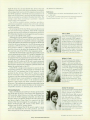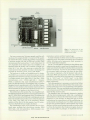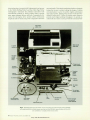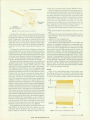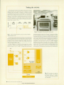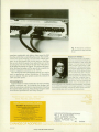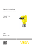
1
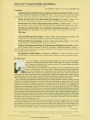
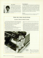
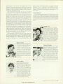
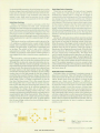
tolerant code-wheel-to-detector-plate spacing.
• Solid mounting of optics holder to endbell assembly. Careful
attention was given here to make sure that the optics holder
would not move or drift and become misaligned. Also we
brought the sides of the endbell up and mounted the encoder
optics assembly upside down compared to the way it is gener
ally done. This allows us to assemble the encoder easily down
onto the motor without the fear of damaging the code wheel.
A spec ¡ally designed fixture that simulates an actual encoder to
test the optical components to ensure operation under worstcase conditions.
LED
LED Holder
Ackno wledg ments
We would like to acknowledge Choung Ta for his efforts in
designing and testing the optical holder and components, code
wheel, and phase plate as well as his efforts on the printed circuit
board of which was inseparable from the product design of
the overall encoder. Also, we would like to thank John Powell for
his contribution in designing the encoder tester electronics.
Arthur K. Wilson
Art Wilson received an MS degree in
mechanical engineering from the
University of Arizona in 1970. He
joined HP that same year as a de
sign engineer. His most recent work
has been the development of the
7470A's optical encoders. He was
born in Tucson, Arizona, is married,
and has one son. Now living in San
' Diego, California, Art enjoys re| storing antique automobiles — his
*
; current project is a 1909 two-cylin» * der Maxwell.
Operational
Amplifiers
Fig. 2. Exploded view of encoder's optical and electronic
assembly.
after the optics assembly has been mounted.
Custom components such as special resistor networks where
applicable. This saves considerable space on the printed cir
cuit board, has a lower net cost, and reduces lead lengths in
low-level signal areas, minimizing electrical interference prob
lems.
Standard components with standard tolerances when possi
ble. For example, using standard-size composition resistors
with 5% tolerance reduces both material cost and, by making it
possible to use automatic insertion machines, labor cost.
Test and assembly tooling to minimize assembly time. For
example, the printed circuit boards are fabricated, loaded, and
tested ten at a time. Then, during final assembly, the encoder is
adjusted to ±10-degree phase accuracy using a specially
designed test fixture.
To meet 2) high-reliability objective the encoder design (Fig. 2)
uses the following;
A single light-emitting diode for the light source.
A custom detector consisting of a single monolithic chip with
four matched photodiodes driven in the short-circuit mode.
A dual on amplifier to drive a voltage comparator on
each channel.
• Collimated see-through method of light sensing that allows for
Daniel E. Johnson
Dan Johnson was born in
Washington, D.C. He attended
Lafayette College, Pennsylvania,
earning a BSEE degree in 1 965, and
the Polytechnic Institute of New
York, earning an MSEE degree in
1967. He came to HP in 1970 and
has made contributions to the 7040
family of X-Y recorders and, more
recently, the optical encoders for
the 7470A. Dan has written one
other article for the HP Journal, and
is a member of the IEEE and vicepresident of the San Diego chapter
of the California Society of Profes
sional Engineers. He is married, has two sons, and lives in Poway,
California. When he is not busy coaching Youth Soccer and Little
League, Dan enjoys travel, camping, reading, sports, and playing
in HP's local Softball league.
DECEMBER 1982 HEWLETT-PACKARD JOURNAL 27
© Copr. 1949-1998 Hewlett-Packard Co.