1
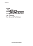
11: DATA LINK COMMUNICATION
Introduction
This chapter describes the data link communication function used to set up a distributed control system.
A data link communication system consists of one master station and a maximum of 31 slave stations, each station com‐
prising any all‐in‐one type or slim type CPU module. When the data link communication is enabled, the master station has 12 data registers assigned for each slave station, and each slave station has 12 data registers for communication with the master station. Using these data registers, the master station can send and receive data of 6 data registers to and from each slave station. No particular program is required for sending or receiving data in the data link communication system.
Data link communication proceeds independently of the user program execution, and the data registers for the data link communication are updated at the END processing.
When data of inputs, outputs, internal relays, timers, counters, or shift registers are moved to data registers using the move instructions in the user program, these data can also be exchanged between the master and slave stations.
The FC4A MicroSmart (except all‐in‐one 10‐I/O type CPU module), OpenNet Controller, MICRO3, MICRO3C, and FA‐3S series PLCs can also be connected to the data link communication system.
One CPU module can be either a master station or a slave station. Data link master and slave cannot be used at the same time.
Master Station
Slave Station 1
Slave Station 31
Data Link Specifications
Electric Specifications
Compliance with EIA‐RS485
Baud Rate
19,200, 38,400, 57,600 bps
Synchronization
Start‐stop synchronization
Start bit:
1
Data bits: 7
Parity:
Even
Stop bit:
1
Communication Cable
Shielded twisted pair cable, core wire 0.3 mm2
Maximum Cable Length
200m (656 feet) / 1200m (3937 feet) total (Note)
Maximum Slave Stations
31 slave stations
Transmit/Receive Data
Transmit data: 186 words maximum, Receive data: 186 words maximum
0 through 6 words each for transmission and receiving per slave station
Special Internal Relay
M8005‐M8007:
M8080‐M8116:
M8117:
communication control and error
communication completion for each slave station
communication completion for all slave stations
FC5A MICROSMART USER’S MANUAL FC9Y‐B1268
11‐1