1
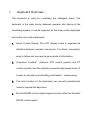
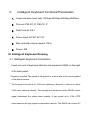
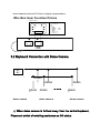
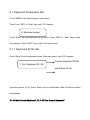
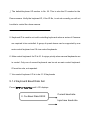
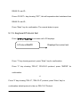
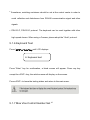
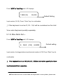
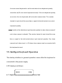
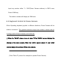
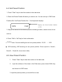
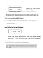
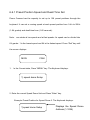
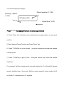
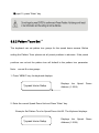
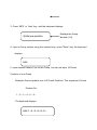
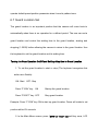
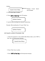
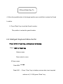
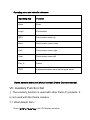
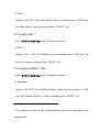
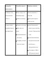
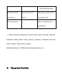
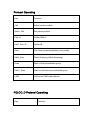
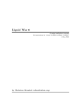
INDEX I. Keyboard Overview ---------------------------------------------------------------------------------------------- 1 II. Technical Parameters ------------------------------------------------------------------------------------------- 1 III. Keyboard Drawing --------------------------------------------------------------------------------------------- 1 3.1 The Keyboard Connection ----------------------------------------------------------------------------------- 2 3.2 The Keyboard Connection with the Dome Camera---------------------------------------------------- 2 IV. Function Key ----------------------------------------------------------------------------------------------------- 3 V Keyboard Parameters Setting --------------------------------------------------------------------------------- 4 5.1Keyboard Parameters Setting -------------------------------------------------------------------------------- 4 5.1.1Keyboard ID No Set ----------------------------------------------------------------------------------- 5 5.1.2 Keyboard Baud Rate Set ---------------------------------------------------------------------------- 5 5.1.3 key-press Sound Set ---------------------------------------------------------------------------------- 6 5.1.4.Matching Resistance Set --------------------------------------------------------------------------- 6 5.1.5.Keyboard Communication Protocol set --------------------------------------------------------- 6 5.1.6 Keyboard Test ------------------------------------------------------------------------------------------ 7 5.1.7 Max Vice Control Number Set --------------------------------------------------------------------- 7 5.1.8. Max Alarm Set ---------------------------------------------------------------------------------------- 8 VI. The Intelligent Keyboard Operation Way ---------------------------------------------------------------- 8 6.1 Keyboard Communication Address Set ------------------------------------------------------------ 9 6.2 The Keyboard Control for Dome Camera ------------------------------------------------------- 9 6.3 Auto Scanning ------------------------------------------------------------------------------------------- 9 6.4 Set Preset Position ----------------------------------------------------------------------------------- 10 6.5 View Preset Position ---------------------------------------------------------------------------------- 11 6.6 Preset Position Parameter Set for the Dome Camera ----------------------------------------- 11 6.6.1 Preset Position Speed and Dwell Time Set --------------------------------------------------- 12 6.6.2 Pattern Tours Set ------------------------------------------------------------------------------------- 14 6.7 Guard Location Set ------------------------------------------------------------------------------------ 16 6.8 Guard Location Parameter Set---------------------------------------------------------------------- 17 6.9 Dome Camera Menu Set ----------------------------------------------------------------------------- 18 VII Auxiliary Function Set -------------------------------------------------------------------------------------- 18 7.1 Wash Brush Set ----------------------------------------------------------------------------------------- 19 7.2 Heating Set ---------------------------------------------------------------------------------------------- 19 7.3Auxiliary Switch 1 Set -------------------------------------------------------------------------------- 19 7.4Auxiliary Switch 2 Set -------------------------------------------------------------------------------- 20 7.5 Proportion Joystick ------------------------------------------------------------------------------------ 21 IX. Exception Handles ------------------------------------------------------------------------------------------- 22 X. The keyboard Key-press Function --------------------------------------------------------------------- 23 I. Keyboard Overview The keyboard is used for controlling the intelligent dome. The keyboard is the main device between operator and device in the monitoring system. It can be regarded as the main control keyboard and as the vice control keyboard. 1. Liquid Crystal Display The LCD display board is regarded as interface between operator and device. It is direct, convenient, easy to follow and conveys large amounts of information. 2. Proportion Joystick1 (Options: PTZ control joystick and PT control joystick, Use this joystick to operate high-speed dome. It is easy to use with good handling and flexible maneuvering 3. The lock function of the keyboard can prevent unauthorized users to operate the keyboard. 4. Provide RS485 control output signal and also offer the standard RS232 control signal. II. Intelligent Keyboard Technical Parameters 1. Communication baud rate:1200bps;2400bps;4800bps;9600bps 2. Protocol: PELCO_D, PELCO_P 3. Data Format: N,8,1 4. Power input: AC/DC 9V-12V 5. Max controlled dome camera:1024 2 6. Power: 5W III. Intelligent Keyboard Drawing 3.1 Intelligent Keyboard Connection Insert one end of keyboard data line into keyboard A2,B2 on the right of its back panel.. Proportion Joystick: The speed of the joystick is a direct ratio to the running speed of the dome camera. 2. The keyboard can set up to 1024 sole addresses. However, it does not control 1024 dome cameras directly. The strength and weakness of the RS485 control signal determines the speed dome quantity. It can control up to 1024 VPTZ dome cameras through signal compensation devices. The RS485 can control 32 dome cameras at most if it has no signal compensation. Wire Box Inner Function Picture Conver t Box 4 5 3 6 2 7 1 8 PI N 1 2 3 4 5 6 7 8 Def i ne AC/DC9V GND RXD RS232 TXD RS232 GND RS485 B RS485 A 12345678 3.2 Keyboard Connection with Dome Camera A2 B2 R S4 R 85 RS485 A RS485 B S4 A dome camera 85 RS485 A RS485 B dome camera RS485 A RS485 B dome camera B △! When dome camera is furthest away from the control keyboard, Please set switch of matching resistance as ON status. 3. R is on behalf of matching resistance. The farthest dome from the control center should be set as its matching resistance in order to minimize RS485 bus reflection and disturbance. The 8thbit of SW3 shows ON status which means the BUS matching resistance has been connected. IV. Function Key Joystick: Control Dome Camera running: Up, down, Left, Right, Left-up, Left-down, Right-up, right-down, camera lens zoom in and zoom out Keyboard joystick can’t control Dome Camera lens zoom in and zoom out. Dome Camera Selection and Auto scanning Control Data Input, Clear and Confirmation Menu Turning, Exit and Preset Position Set Dome Camera Lens Control and Keyboard Lock and Unlock LCD Data Display Function Key Explanation is As Below: KEY Function 0-9 Data key Clear Clear the inputted number on the DATA display area. MON matrix monitor selection CAM Dome Camera address selection Enable Alarm open set 4 Shift+ Enable Alarm close set 4 Shift+Clear Clear Alarm Pan_A Set the start point of dome camera auto scanning. Pan_B Set the end point of dome camera auto scanning. Auto Finish Dome Camera auto action/ select menu items down Shift+ Auto Adjust Dome Camera pattern tour function Scan Startup scanning group(model NO.1) Shift+ Scan Startup scanning group(model NO.2) Call Call Dome Camera preset position function Shift+Call Set Dome Camera preset position function MPX Clear Dome Camera preset position function/ select menu items up MENU Enter keyboard menu Other key such as GRP, SEQ, NEXT, AREA, DVR, is designed for other terminal device. Camera Lens control Zoom in: Press <ZOOM in> key/ joystick make a veer rotation Zoom out: Press <ZOOM out> key/ joystick make a restores rotation Focusing Far: Press <FOCUS far> key Focusing near Press <FOCUS near> key IRIS open: Press <IRIS open> key IRIS close: press<iris close> key V. Keyboard Parameters Setting △! The keyboard intelligent keyboard baud rate and communication protocol should be consistent with that of the dome camera. 5.1 Keyboard Parameters Set Press “MENU” key enter Keyboard main menu Then Press “MPX” or “Auto” key until LCD displays: 2) Keyboard setup Press “Enter” key into keyboard set up menu. Press “MPX” or “Auto” key to enter the submenu. Press “EXIT” key to exit to the main menu. 5.1.1 Keyboard ID No Set Press “Enter” key on keyboard screen “Keyboard setup” until LCD displays: 1. Cur. Keyboard ID: XX 0=Mast,1→16=Slave:XX Current keyboard ID No. Input New ID No. Input the number (0-16), press “Enter” key for confirmation. New ID will be in effect immediately. ID: 00 Main Control Keyboard6, ID: 1-16 Vice Control Keyboard7. △! The default keyboard ID number is No. 00. This is also the ID number for the Dome camera. Verify the keyboard ID, if the ID No, is not set correctly you will not be able to control the dome camera. 5. Keyboard ID is used to set multi controlling keyboards when a series of Cameras are required to be controlled. A group of speed domes can be supported by one main control keyboard and 16 vice control keyboards. 6. Main control keyboard: Its ID is 00. It enjoys priority when several keyboards are in control. Only one of several keyboards can be set as main control keyboard. ID must be sole, not repeated. 7. Vice control keyboard: ID is to be 01-16 keyboards 5.1.2 Keyboard Baud Rate Set Press “MPX” or “Auto” key until LCD displays: 2. Cur.Baud Rate:XXXX 12/24/48/9600:XXXX Current baud rate. Input new baud rate Optional baud rate: 9600, 4800, 2400, and 1200 Default baud rate: 9600bps. Input your required baud rate in DATA area, and press “Enter” key for confirmation. New baud rate is in effect immediately. 5.1.3 Key-press Sound Set Press “MPX” or “Auto” key until LCD displays: 3. Current sound: ON Displays current set Select Sound preference Your select: Press < F1/ON > key showing “ON”; turns on the sound function. Press “Enter” key for confirmation. Press< F2/OFF > key showing “OFF”; turns off the sound function. Press “Enter” key for confirmation. The normal sound status is open. 5.1.4. Matching Resistance (150Ω) Set Press “MPX” or “Auto” key three times until LCD displays: 4. Match resister: ON Displays the current set Press< F1/ON > key showing “ON”, this will place suited resistance between Your select:ON RS485 D+ and D-, Press< F2/OFF > key showing “OFF”, this will separate suited resistance from RS485 D+ and D-, Press “Enter” key for confirmation. The normal status is open. 5.1.5. Keyboard Protocol Set Press “MPX” or “Auto” key four times until LCD displays: Displays the current set 5.Protocol:MatPD New Protocol: Press “1” key showing protocol, press “Enter” key for confirmation. Press “2” key showing “PEL-D”, PELCO-D 9protocol, press “ENTER” for confirmation. -6Press “3” key showing “PEL-P”, “PELCO-P” protocol, press “Enter” key for confirmation default protocol is the our PELCO-P Protocol. 8 Sometimes, matching resistance should be set at the control center in order to avoid reflection and disturbance from RS-485 communication signal and other signals. 9. PELCO-P, PELCO-D protocol: The keyboard can be used together with other high speed domes. When using a Camera, please adopt the “Vinte” protocol. 5.1.6 Keyboard Test Press “MPX” or “Auto” key until LCD displays: 6. Keyboard test Press “Enter” key for confirmation, a blank screen will appear. Press any key except the <EXIT> key, the relative name will display on the screen. Press <EXIT> to leave the testing status and return to the main menu. 5.1.7 Max Vice Control Number Set 10 Press “MPX” or “Auto” key until LCD displays: 7.MAX(16) SLAVE Default Setting ID:XX Input number (00-16), Press “ Enter” key for confirmation. Input new ID:XX △! If the keyboard is set as:01,02…16,it will be considered as the total Vice control keyboard quantity separately. 5.1.8. Max Alarm Set 11 Press “MPX” or “Auto” key until LCD displays: 8. MAX (239) ALARM Default setting ID:XX Input number, the biggest alarm input terminal number is 239. Press “Enter” key for Input new ID:XX confirmation △! If the keyboard is set as: 000,001,002…239,the total relative quantity for Alarm input terminal will be in operation. 10 When there are two or more than two keyboards in one system, please use the main control keyboard to set the total desired vice keyboard quantity should be set(16 vice control keyboard at most). If the vice keyboard quantity are not set, the vice keyboards will not control camera dome. The number desired to input should be more than or equal to the total actual vice control keyboard quantity. 11 You should set the total alarm input terminal quantity for alarm dome camera if such dome camera is adopted. The number desired to input should be more than or equal to the total actual alarm input terminal quantity. One dome camera has 4 alarm input, i.e. 59 alarm dome camera can be connected with the keyboard at most. VI. Intelligent Keyboard Operation The startup interface is general operation menu after the keyboard is connected to the power supply. LCD displays as follows: MON CAM 6.1 Keyboard Communication Address Set DATA 01 0001 0000 Input any number within “1~1024”(Dome Camera address) in DATA area, Press<CAM>key. The relative number will display on CAM area. 6.2 Keyboard Control for Dome Camera When Operating keyboard joystick in different directions, Dome Camera will do relative movement. The joystick excursion scope from center is direct ratio to running speed of Dome Camera.(0.4°/S-280°/S) △! When the “DATA” column does not show “0”,the “DATA” column displays the Address of the dome camera. When the “DATA” column shows “0”, the “CAM” column displays the address Of the dome camera. (Take “Pelco P” protocol for example to operate Dome Camera) 6.3 Auto Scanning (2 Points Scanning, 360°Scanning) A.2 Points Scanning 12 The operator can also run a simple point-to-point scan (also called back-and-forth scanning). To do this, set Preset Point A first (at the same time set the dwell 13 time at Point A), and then set Present Point B (at the same time set the dwell time at Point B). Finally execute an outer command to scan between points A and B. 12 2 points scanning: It means scanning between two points. The speed is: Grade1, Grade 2·····Grade64 (from slow to fast) Press “Clear” key on the keyboard DATA area to delete value on DATA column. 1. To set Point A. Move the joystick to the desired position. 2. In the Main Menu enter a dwell time for Point A. Example: If Dwell time is 2 seconds the keyboard displays: 3. Press “PAN A” key. 4. To set Point B, move the joystick to the desired position. 5. In the Main Menu enter a Dwell time for Point B. 6. Input the grade Speed (1-64) and Press “AUTO” key. This will start up 2 points Scan B.360°Scanning 14 The Operator can also start an auto cruise scan. This scan will rotate 360° from the desired position. Press “Clear” key on the keyboard DATA area to delete value on DATA column. 1. In the Main Menu, input desired cruise group No. Example: Desired Group No. is 4 the keyboard displays: MON CAM 2. Press “Shift + Scan” key to place PTZ into cruise scanning. DATA OR 01 0001 0000 1. Move the joystick to desired position. 2. Input the running speed (1-64) and then input Shift + AUTO key. △! Shake the keyboard joystick to stop auto scanning. 6.4 Set Preset Position 1. Press “Clear” key to clear the number in the data area. 2. Enter the Preset Position Number you wish to set. You can set up to 128 Preset Positions.Ex. Set Preset Position No. 1, the keyboard displays: MON CAM Displays the Preset Position Number (1-128) 3. Adjust the camera to the desired position including location, camera zoom, focus DATA and iris. 01 0001 0000 4. Press “Shift + Call” key for final confirmation. 13 Dwelling 14 time: Can set dwelling time at one preset position: 1S,2S ……. 60S 360°scanning: 360°scanning at one preset position. Dome speed is: Grade1, Grade 2, . Grade 64 ( from slow to fast) 6.5 View Preset Position 1. Press “Clear” key to clear the number in the data area. 2. Input the address of the dome in the Data area, press down<CAM> key and show it in DATA area. 3. Input the preset position you would like to view. Example: View preset position No. 5 MON 4. CAM Press “CALL” key. DATA Displays the Preset Position Number (1-128) The dome will move to the Preset Position No. “CALL” key. dome camera will nun to the present position you △! After pressing 01 0001 0000 Would like to view at Grade 64(280°/S) speed. 6.6 Preset Position Parameter Set for the Dome (Pelco P protocol has this function) 15 Press “MPX” or “Auto” key until LCD displays: 1) speed dome Setup Press “Clear “key to delete previous data. Input required address Number:0000 code XXXX(1-1024)for control. Press “Enter” key for confirmation Press “Enter” key into preset position set of dome camera. 6.6.1 Preset Position Speed and Dwell Time Set Dome Camera has the capacity to set up to 128 preset positions through the keyboard. It can set a running speed at each preset position from 0.4/s to 280/s (1-64 grades) and dwell time from (1-60 seconds). Note: can rotate at low speeds and at fast speeds. Its speed can be divided into 64 grades. 1 is the lowest speed and 64 is the fastest speed. Press “Exit” key until the screen displays: MON CAM DATA 1. In the Current state, Press “MENU” key. The Keyboard displays: 01 0001 0000 1) speed dome Setup Number:0000 2. Enter the correct Speed Dome Unit and Press “Enter” key. Example: Preset Position for Speed Dome 3. The Keyboard displays: 1)speed dome Setup Number:0003 Displays the Speed Dome Address (1-1024) 3. Now the Keyboard displays: Preset position (1-128) Running speed (1-64) 1)Position:000 Dwell time (1-60) Speed:00 Time:00 Press “F1/ON” the keyboard to move the cursor up and down 4. Press “Clear” key to delete previous data before programming to a new preset position. 5. Enter desired Preset Position and Press “Enter” key. 6. Press “F1/ON”key to get to Speed. Using the number keys enter the desired running speed. 7. Press “F1/ON”key to get to Time. Using the number keys enter the desired dwell time. For example: Set the running speed of preset position No. 6 as Grade 64 (fastest speed), dwelling time is 5 seconds. Set the running speed of preset position No.2 as Grade 10, dwelling time is 10 seconds. 1. Press “MPX” or “Auto” key. 2. Press “Clear” key to clear the data. 3. Input 06 (Note: Setting the Preset Position No. 6) press “Enter” Key to Confirm. 4. Press “F1/ON” key to move the cursor to Speed:00← 5. Input 64, press “Enter” key 6. Press “F1/ON” key to move the cursor to Time:00← 7. Input 05, press “Enter” key 8. Press F1/ON to move the cursor back to 1.Position:001← 9. Press “Clear” to delete 0006 10. Input 02, press “Enter”key 11. Press “F1/ON” key to move the cursor to Speed:64← 12. Press “Clear” to delete 64 13. Input 10, press “Enter”key 14. Press t “F1/ON” key to move the cursor to Time:05← 15. Press “Clear” to delete 05 16.Input 10, press “Enter” key 6.6.2 Pattern Tours Set 16 The keyboard can set pattern tour groups for the speed dome camera. Before setting the Pattern Tours please set all preset positions in advance. If the preset positions are not set the pattern tour will default to the pattern tour parameter. Note: can set 8 cruise groups. 1. Press “MENU” key, the keyboard displays: 1)speed dome Setup Displays the Speed Dome Address (1-1024) Number:0000 2. Enter the correct Speed Dome Unit and Press “Enter” key. Example: Set Pattern Tour for Speed Dome Unit 02. The Keyboard displays: 1)speed dome Setup Number:0002 Displays the Speed Address (1-1024) Dome 3. Press “MPX” or “Auto” key, until the keyboard displays: 3)Add pre-position Displays the Group Number (1-8) Group Number:0 4. Input a Group number using the number keys, press “Enter” key, the keyboard displays: Add 5. Input desired Pattern Tour for the Group. You can set up to 16 Preset Positions in one Group. Example: Desired pattern tour of 6 Preset Positions. The sequence is Preset Position No. 1–2–3–4–5–6– The keyboard displays: Add:1→2→3→4→5→2→ 6. Press ”Enter” key to confirm Pattern Tour. Note: When completed, Press “F1/ON” to close and exit. To Start the Scan: In the Main Menu enter the Group Number and Press SCAN. This dome can set 8 cruise groups with a Max of 16 cruise points. Each group (1-128 points at any preset position). Set the preset position at each of the cruise groups Dwell time at each preset position can be customized at a different time (1-60 seconds). The speed to each preset position can be different (1-64 grades) Default cruise group will auto scan by starting at present position point No. 1 to preset position point No. 16. 16 Pattern tours: Layout different preset position for Dome Camera as one group, make the camera scan as set route in advance. The running speed and dwell time of each preset position can be programmed. Two pattern tours styles can be used: A .To-and-from Scanning 1-2-···········.-16-1-2-···········-16-1-··········· Make an auto circle scanning by points. Press “EXIT” key and exit to default status of the keyboard. Input cruise Number adjust key SCAN into to-and-from scanning (as the above route) B. Cruise Scanning 1-2···········15-16-15-···········-2-1-2-···········-15-16-15-···········Make an auto cruise scanning Press “EXIT” key and exit to default status of the keyboard. Then input cruise group No and then input Shift + Scan. Into cruise scanning (as the above route). Select: Add the preset position to cruise Press “Enter” key for confirmation after adding a preset position. Press “F2/OFF” key exit when setting is finished. Please set the preset position parameter before setting its pattern tours. If not setting dome preset position, Dome Camera will operate default preset position parameter when it runs its pattern tours. 6.7 Guard Location Set The guard location is an important position that the camera will come back to automatically when there is no operation for a defined period. The user can set a guard location and control the waiting time to the guard location, starting and stopping (1-255S) before allowing the camera to return to the guard location. Use the keyboard to set the guard location and its waiting time. Turning the Guard Location On/Off and Setting delay time to Guard Location 1. To set the guard location to start or stop (The keyboard recognizes this action as a Switch): ON: Start OFF: Stop Press “F1/ON” key ON Press “F2/OFF” key OFF Startup the guard location Stop guard location Example: Press “F1/ON” key ON to start up guard location. Dome will rotate to set position within XX seconds. 2. In the Main Menu screen, press “MPX” or “Auto” key,until key once, LCD displays: 1)speed dome Setup Displays Current Speed dome address 3. Press “Enter” key to Confirm. Number:0000 4. Press “MPX” or “Auto” key,until LCD displays: 4)Watch Position Time:000 Switch 5. Input the desired waiting time using the number keys: Example: After inputting time: 05, press “Enter” key. 4)Watch Position Time:005 Switch 6.8 Guard Location Parameter Set 1. When the keyboard is under default (Main Menu) status, press “MPX” or “Auto” key, until the keyboard displays: 1) speed dome Setup Number:0000 2. Press “Enter” key to confirm. 3. Press “MPX” or “Auto” key, until the keyboard displays: 3.Press Enter Key To Setup Watch Position 4. Move the joystick/rocker to the target position you would like to set as the Guard Location. 5. Press “Enter” key to set the Guard Location. The position is set as the guard location. 6.9 Intelligent Keyboard Menu Set for Press “MPX” or “Auto” key, until keyboard will display: Press “MPX” or “Auto” key 5)dome menu Press enter to menu 5 Dome menu Data:0000: Data:0000 → Press “Clear” key to delete previous data, input required address of (1-1024),press “Enter” key. Operating menu see below for reference: Operating Key Function Enter Enter Login Exit function MPX Dome menu cursor up Auto Dome menu cursor down Call Dome menu cursor right Scan Dome menu cursor left Pan_A Select DVR Keyboard function menu exit to upper menu Dome camera menu set should consult Dome Camera manual. VII. Auxiliary Function Set △! The auxiliary function is used with other Pelco P products. It is not used with the Dome camera. 7.1 Wash Brush Set 17 Press “MPX” or “Auto” key until LCD display as below: 3) Wash Number: 0001 OFF→Set “Wash Brush” open by pressing down “F1/ON” key, Set “Wash Brush” close by pressing down “F2/OFF” key. 7.2 Heating Set 18 Press “MPX” or “Auto” key until LCD display as below: 4) Warm Number: 0001 OFF→Set “Heating” open by pressing down “F1/ON “key, Set “Heating” close by pressing down “F2/OFF “key. 7.3 Auxiliary Switch 1 Set Press “MPX” or “Auto” key until LCD display as below: 5) Auxiliary#1 Number: 0001 OFF→Set “Auxiliary Switch 1” open by pressing down “F1/ON “key, Set “Auxiliary Switch 1” close by pressing down “F2/OFF “key. 17 This function is used for the frontal terminal device with the wash brush function only. 18. The fan and heater in the speed dome camera is always under auto temperature control status. This function will auto start when the temperature reaches higher point or lower point. 7.4 Auxiliary Switch 2 Set Press “MPX” or “Auto” key until LCD display as below: 6) Auxiliary#2 Number:0001 OFF→Set “Auxiliary Switch 2” open by pressing down “F1/ON “key, Set “Auxiliary Switch 2” close by pressing down “F2/OFF “key. 7.5 Proportion Joystick △! This function has been set well before the keyboard leaves the factory. The speed of the Joystick is a direct ratio the running speed of the dome. If it is not a direct ratio; reset the keyboard joystick parameter. Press “MPX” or “Auto” key until LCD displays: 8) Joy Stick Set Tilt:000 Pan:00O→ Display Joystick value(Up, Down, Left, Right) 8.1 Set Joystick middle value (dwelling time) When stop on the middle part, set joystick middle status by pressing”AREA” key. 8.2 Set joystick up limit value Move the joystick to top (up), set its upper limit value by pressing ”SEQ” key 8.3 Set joystick down limit value Move the joystick to bottom, set its lower limit value by pressing ”MON” key 8.4 Set joystick left limit value Move the joystick to left side, set its left limit value by pressing ”GRP” key 8.5 Set joystick right limit value Move the joystick to right side, set its right limit value by pressing ”Next” key 8.6 Set joystick restores limit value (limited for PTZ keyboard –only)Move the middle pillar of joystick to the bottom extrorsely, set its restores limit value by pressing ”Pan_A” key 8.7 Set joystick veering limit value (limited for PTZ keyboard –only) Move the middle pillar of joystick to the bottom veer; set its veering limit value by pressing”Pan_B” key See below chart for setting reference. Operating Key Function Pan_A Set joystick restores limit value Pan_B Set joystick veer limit value GRP Set joystick left limit value Next Set joystick right limit value SEQ Set joystick up limit value MON Set joystick down limit value AREA Set Joystick middle value IX. Exception Handles Exception Possible reason Relative solution No display on the 1.Power supply is not 1.Check connection of screen when the connected properly power line power on 2. Watt is not enough 2.See if power supply is phenomena AC/DC 9V-12V No way to control 1.Protocol is not correct designated dome or 2.Baud rate is not protocol accords with that high speed dome correct of dome or high-speed ball 3.Controlled address is or not. not correct 4.the polarity of control line is not correct 1.Check if the keyboard 2.Check if the baud rate of the keyboard accord with that of dome or high-speed ball or not. 3. The number in CAM or DATA area can’t accord with the object address No Bi sound when Key-press sound is Start up key-press sound in pressing key closed the keyboard set Other phenomena Back to manufacturer for maintenance △! When using the keyboard to control other dome cameras, keep the keyboard setting (Baud rate, protocol, address) consistent with the dome camera. Some dome camera addresses have a±1 difference the keyboard does not. X. Key-press Function Protocol Operating Key Function Call Adjust preset position Shift + Call Set preset position Pan –A Limited Site A Shift_ Pan –A Limited B Auto Line Scan (scanning between two points) Shift _Auto Panel Scanning (Mode Scanning) Scan Start up the perambulate group Shift + Scan Start up intercourse perambulate group CAM LCD show CAM area address PELCO_D Protocol Operating Key Function Call Adjust preset position Shift + Call Set preset position MPX Clear preset position