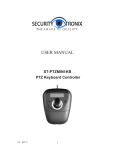
1
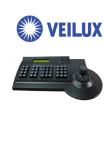
Keyboard Controller
Users' Manual
Contents
1
1. Summary ------------------------------------------------------------------------------------------------------------------- 3
1.1 Notice ---------------------------------------------------------------------------------------------------------------------- 3
1.2 Function & Characteristic -----------------------------------------------------------------------------------------------3
1.3 Technical Data ------------------------------------------------------------------------------------------------------------3
2. Keyboard connection ------------------------------------------------------------------------------------------------------- 4
2.1. RS485 interfaces-------------------------------------------------------------------------------------------------------------- 4
2.2 Connect matrix -----------------------------------------------------------------------------------------------------------------4
2.3 Direct connect with Dome--------------------------------------------------------------------------------------------------5
2.4 Keyboard connection in the System-----------------------------------------------------------------------------------------5
3. Keyboard operation instruction --------------------------------------------------------------------------------6
3.1 Electrify ------------------------------------------------------------------------------------------------------6
3.2 LED display screen ---------------------------------------------------------------------------------------------6
3.3 Joystick controls dome -------------------------------------------------------------------------------------7
3.4 Rigger the aim dome -----------------------------------------------------------------------------------------7
3.5 Dome lens control -----------------------------------------------------------------------------------------7
3.6 Set dome function--------------------------------------------------------------------------------------------7
3.6.1 Preset-----------------------------------------------------------------------------------------------------------7
3.6.2 Scan--------------------------------------------------------------------------------------------------------7
3.6.3 Pattern----------------------------------------------------------------------------------------------------------7
3.6.4 Cruise----------------------------------------------------------------------------------------------------------8
3.7 Call dome main menu------------------------------------------------------------------------------------------8
3.8 Matrix Control-----------------------------------------------------------------------------------------------8
3.8.1 Switch dome in order-----------------------------------------------------------------------------------------8
3.8.2 Call matrix main menu---------------------------------------------------------------------------------------8
3.8.3 Confirm after program---------------------------------------------------------------------------------------8
3.8.4 Change object monitor---------------------------------------------------------------------------------------8
4. Keyboard control---------------------------------------------------------------------------------------------------------------8
4.1 Keyboard parameter setup---------------------------------------------------------------------------------------------------9
4.1.1Keyboard ID setup-----------------------------------------------------------------------------------------------------------9
4.1.2 Keyboard baud rate setup-------------------------------------------------------------------------------------------------10
4.1.3 Navigation key adjust------------------------------------------------------------------------------------------------------10
4.1.4 Display Keyboard information -------------------------------------------------------------------------------------------11
4.2 Dome setup-------------------------------------------------------------------------------------------------------------------11
4.2.1 Pre-set setup----------------------------------------------------------------------------------------------------------------11
4.2.2 Dome Scan setup-----------------------------------------------------------------------------------------------------------12
4.2.3 Pattern setup----------------------------------------------------------------------------------------------------------------12
4.2.4 Tour setup---------------------------------------------------------------------------------------------------------------13
4.3 Protocol setup---------------------------------------------------------------------------------------------------------------14
4.4 Exit Keyboard menu-------------------------------------------------------------------------------------------------------14
5. Appendix ----------------------------------------------------------------------------------------------------------------------14
5.1 RS485 Bus general knowledge--------------------------------------------------------------------------------------------14
5.2 Keyboard shortcut instruction---------------------------------------------------------------------------------------------16
6. Keyboard menu index---------------------------------------------------------------------------------------------------------18
2
1. Summary
The keyboard is a universal keyboard of security monitoring series, which can control the ball-type
integrated camera of all kinds protocols matrix, which has been equipped with Joystick which can
control the revolving of the camera and the zoom magnification of lens; with the LCD screen and the
function of back-light; which can display the current operation order the control protocol name the
current dome ID the current monitor ID and the state of
joysticks. The user can control the CCTV
system more easily with the joystick and the LCD screen.
1.1Notice
Please read the manual carefully and reserve it.
Please advert to the notice in manual.
Please don't place the keyboard in the moist place.
1.2 Function
and Characteristic
●Rs485 Bus Line, and a keyboard can connect
31 domes at most in the direct control mode.
●can be compatible with all kinds of protocols.
●can control the Iris Focus and Zoom.
●can set and call
the preset, run the scanning the pattern and the tour。
●can control the matrix and through which
can control the dome indirectly.
●equipped with the 3D Joystick and a LCD screen
●The LCD can display the current operation order, the control protocol name, the current dome ID ,the
current monitor ID and the state of joysticks.
●Infrared ray emission,emission the same data & content as RS485
1.3 Technical
Data
★Electrical character
Input voltage:9V-12V DC
Rating Power:0.5W
★Communicate character
Communicate interface:RS485×1,infrared emission
Communicate frequency:2400、4800、9600、19200bps
Communicate distance:RS485 can reach 1.2Km,infrared emission reaches 10m.
★Operational environment
Operating temperature:0℃~50℃
Relative humidity less than 90%
★Physical property
L*W*H=168mm*136mm*105mm
Weight:0.400 kg
3
2.Keyboard Connection
There is interface on the back of the keyboard, which equipped with kinds of communication
Interface RS485 and infrared emission, which can connect with and control kinds of peripheral
equipments.
2.1. RS485 interfaces
Rs485 interfaces are on the 2bit ribbon cable connection of the keyboard.RS485 A+ B-) can
connect with the dome when the keyboard controls the dome directly;RS485 A+B-can connect with
DVR or other keyboards when the keyboard controls the dome by matrix
Power/RS485
IR remote control
2. 2 Direct connect with Dome
Keyboard connect the Dome wit RS485。The RS485 interface of the Dome is on the commutator of the
Dome.Press the metal button in the hanging frame,open the commutator, will find a 4bit power jack,follow the
surface instruction to find RS485(A+,B-)follow the instruction。Maybe a different connect way when come from
different manufacturer。
Figure 2-3.1
DC 12V A+ BRS485 A+B-
Dome
Keyboard
4
2. 3 Keyboard connection in the system
Indirect control the dome when connect with matrix(as figure 2-4.1)
。contrariwise will control the domes
directly,Parallel connect the keyboard and dome to the bus of RS-485,all the keyboard can control any dome
among them, under this way, the add of the main keyboard should be “1” and baud rate should be 9600bps(as
figure 2-3.1)
Figure
2 -4.1
matrix
Dome1
Keyboard
Dome2
Caution
1、the max quantity of master equip and be charged equip controlled by a RS485 bus is,so when use the
keyboard to control direct the max dome quantity is 3
2、max quantity keyboard in a system is 4,also the 4 keyboards should be different ID
Figure 2-4.2
Keyboard 1
Keyboard 3
Keyboard 4
Keyboard 2
Dome 1
Dome 5
Dome 2
Dome 6
5
Dome 3
Dome 7
Dome 4
Dome 8
3. Keyboard operation instruction
LCD screen
lens control
3D joystick
Number keys
Function keys
Figure 3-1.1
Attention please because different system have some different special operation ways, so should consider the
actual requirement when operation in some special systems
3.1 Electrify
When the power is on, the keyboard will automatically check the baud rate、protocol of the keyboard、aim
dome and the aim monitor, and all the info. will be displayed on LCD screen.
Attention
The joystick should be nil when keyboard is initializing
3.2 LCD display screen
LCD screen display contents:aim dome、aim monitor and baud rate etc. And at the end of the content will
show the current operation order and the states of joystick, as follows figure show .When operation,LCD
back light will on,and will be off 10s after the operation。
Camera
ID:001
Monitor
ID:001
Protocol : Pelco-d
Baud rate :2400bps
Figure 3-1.2
6
3. 3 Joystick Controls Dome
Functions of the Joystick: Dome rotation control and Object dome menu setup。
●When operate the joystick at will to any direction
Dome will rotate at the same direction ,and the direction will
be displayed below right corner as
When for menu setup,
save the setup;
for the upper menu item,
for the next menu;
“
” for the sub menu or
for un-save or exit。
●Direct proportion between the speed of the Dome and the lean angle of the navigation keys,lange lean
angle ,faster rotation speed。
3. 4 Rigger the aim dome
【N】+【CAM】
【N】for Number,input the serial number of the Dome,Press【CAM】key to amend the add of the aim dome。
3.5 Dome lens control
●Zoom:
Users can control the zoom by rotating the joystick
●Focus:
Press【FAR 】key
Press【NEAR】key
focus for far objects。
focus for vicinity objects。
Normally ,Zoom and focus will be adjusted automaticly by the dome, and with the【FAR 】
【NEAR】 to realize the
manual zoom and focus
●Iris:
Press【OPEN】key,manual Iris accretion,whole white picture means max iris
Press【CLOSE】key ,manual Iris minish,whole black picture means min.iris
3.6 Dome function operation
3.6.1 Pre-set
Pre set:
【SET】+【N】 + 【PRESET】
Adjust pre set:
【N 】+【PRESET】
【N】for the number of the pre-set。
3.6.2 Scan
Left borderline:
【SET】+【1】+【SCAN】
Right borderline:
【SET】+【2】+【SCAN】
star:
【1】+【SCAN】
Enter the menu to set when need change the scan speed。
3.6.3 Pattern
7
●design path setup:
【SET】+【N 】+【PATTERN】+path+【SET】+ 0 +【 PATTERN】
Press【SET】key,input the number of design scan(1-4)
,press【PATTERN】key,enter the path setup state,
when ending press 【SET】key first,then press【0】key,then 【PATTERN】key,
●starting the design scan:
【N】+【PATTERN】input the design scan number(1-4)
,press【PATTERN】key to
starting,
3.6.4 Cruise
starting: 【N】 +【TOUR 】/【TOUR】 cruise number first ,then 【TOUR】key,starting the cruise。
Direct press the 【TOUR】 key when the system only have one cruise .。
3.7 Call Dome main menu
【9】+【5】+【PRESET】
:Input 95,press【PRESET】key, aim Dome,menu will display on the monitor。
3.8 Matrix control
3.8.1 switch dome orderly
The matrix can connect the 16pcs High Speed Dome. All the information like the Series NO, Data and time will
display on the monitor while switch the speed dome camera. 【PREV】: switch to previous camera;Press 【PREV】
2 Sec,it will keep switch till the whole 16 high speed dome. Press【Stop】to stop the switching.【NEXT】
:back
forward. Press【NEXT】it will switch to the next camera; Press【NEXT】2 Sec, it will keep back forward switch
till the final 16th camera. You can use the 【Stop】key to stop the operate
3.8.2 Call matrix main menu
【SHIFT】+【SET】
: Call the main menu, the menu will display on the object monitor. How to use the keyboard
Setting the matrix? Pls refers the matrix operate manual.
3.8.3 Confirm after program
【ENTER】
:after the matrix is
programmed, press【ENTER】, reflects confirm after program.
As for the detail program, please refer to the matrix operation manual.
3.8.4 Change
object monitor
【N】+【MON】Input the monitor ID, then press MON the image and the menu of the dome that you
controlled by keyboard will display in the object monitor
4、
、Keyboard menu control
●Keyboard parameter set up
Turn on the power and press the【MENU】, the system information will display on the screen, like the
picture(4.1-1), press again the system information will disappear. You can do all the keyboard operation while in
the standby condition or the system information display condition.
Press【MENU】and hold on 2 sec, you will enter the main menu as the picture (4.1.1-1)show. All the menu
setting need enter the main menu first,and use the correspond NO or the Joy calibrate to move UP and DOWN.
While you find the item you need, move the joystick RIGHT or LEFT to enter the menu.
1. Keyboard setup
2. Dome setup
3. Protocol select
4. Exit menu
8
‘
Picture 4.1-1
● Save the setting
After setting the function you need, press【ENTER】to save the setting. After finishing the setting, the TFT will
display“Success”.
● Back to Previous menu
Press the【PREV】key to back to the previous menu.
4.1 Keyboard parameter setting
4.1.1 Keyboard ID set up
1、Enter the main menu
LCD will display (picture4.1.1-1)
1. Keyboard setup
2. Dome setup
3. Protocol select
4 .Exit menu
Picture4.1.1-1
2、Press【1】to select the keyboard setting as LCD(Picture4.1.1-2)
1.
2.
3.
4.
Set KB ID(1-64):Set Baudrate:2400bps
Joy calibrate
About keyboard
Picture 4.1.1-2
3、Press【1】again will show the picture(Picture4.1.1-3)
1.Set KB ID(1-64):Picture4.1.1-3
4、Press【1】to select the ID Setting (Picture4.1.1-4)
1.Set KB ID(1-64):-
Picture 4.1.1-4
Use the ”Number key” to select the camera ID in the range (1-64)
;And then press the 【Enter】to save, the screen
will display Success as picture( 4.1.1-5).
Success
Picture4.1.1-5
If the NO you input is beyond the range1~64, it will display Error as picture(4.1.1-6).
Error
Picture 4.1.1-6
9
5、Press 【PREV】or use the shake toward to LEFT to back to previous menu.
Warning::
The camera ID default is 1. only one keyboard in a system, it must set to ID as “1”.
Several keyboards work together at most is 4 keyboards, and it must has one keyboard
ID is ID1, otherwise all the keyboard can not work. And the LCD will show as picture
4.1.2 Keyboard Baud Rate Setting
Enter the main menu as the TFT picture (4.1.1-1) show..
Press【1】will show on the TFT as picture(4.1.1-2)
Press【2】select the Baud Rate setting, as Picture(4.1.2-1)
2. Set Baud rate: 2400bps (4800bps/9600bps/19200bps)
Picture 4.1.2-1
2400bps\4800bps\9600bps\19200bps is available(commonly under the IR emission mode, baud rate is 2400bps or
4800bps),You can select the Baud rate you need and press the 【ENTER】 to save. If you operate success, the
screen will show“Success”.
Press 【PREV】or move the joystick to LEFT to back to previous menu.
Warning:
If connect to the matrix, baud rate must be 9600bps. Several keyboards work together, it must use
9600bps or 19200bps
4.1.3. Joystick calibrate
When the joystick at midpoint position ,pls enter the menu to enter the “ joystick calibrate.” Item
When calibrating, the joystick must be in a natural state. Enter the main menu
LCD will display (picture4.1.1-1)
2、Press【1】to select the keyboard setting as LCD(Picture4.1.1-2)
3. 2.Press【3】into joystick calibrate as LCD(Picture4.1.3-1)
Joystick is free
then press Enter
Picture4.1.3-1
Press【Enter】and the joystick calibrate is finished as LCD display (Picture4.1.3-2)
Success
Picture4.1.3-2
Attention: when calibrating the joystick, pls make sure the joystick is in the midpoint position
4.1.4 Keyboard information display
10
Enter the keyboard information display menu as LCD(Picture 4.1.1-2)
Press【2】to check the keyboard information as LCD(Picture 4.1.4-1)
4.2 Dome set up
4.2.1 Preset set up
Enter the main menu as picture (4.1.1-1)and press【2】 to enter the dome setting menu as picture (4.2.1-1);
This part you can set the follow function: Preset, Scan, Pattern, Tour.
1.
2.
3.
4.
Set dome preset
Set dome scan
Set dome pattern
Set dome tour
Picture4.2.1-1
Press【1】 enter the dome Preset function setting as picture (4.2.1-2)
1. Save preset
2. Show preset
3. Clear preset
Picture 4.2.1-2
Item 1 : Save preset;item 2 : Show the preset; Item 3: delete the preset
Press【1】 enter the preset, you can input the preset NO as picture(4.2.1-3)show.
Preset num:
(1-128)
Press PREV to back
Picture 4.2.1-3
After enter the preset menu you can use navigate key control the dome directly, and input the preset NO to save as
the picture 4.2.1-4 show. And on the TFT screen will display SUCCESS.
Success!
Picture 4.2.1-4
Press【Prev】back to previous men.
Warning:
Under commonly mode, Dome can not control by operate the keys and move the joysticks ;
While enter the dome preset menu, the keyboard navigate keyboard can directly control the dome
and lens control zone also can control the dome’s lens.
Press【2】enter the “Show the preset” menu as picture 4.2.1-5
Preset num:
(1-128)
Press PREV to back
Picture 4.2.1-5
11
Input the Preset NO that want delete, and press the 【ENTER】to call it, and the TFT will display“Success" .
Use the navigate
Key or 【PREV】 back to previous menu. Press【3】 enter the “clear the Preset” to clear preset information as
picture 4.2.1-6 show.
Preset num:
(1-128)
Press PREV to back
Picture 4.2.1-6
Input the PRESET NO which you want to clear, and press the Enter to clear it, and it will show “Success"
and back to previous menu.
4.2.2 Dome Scan set up
Enter the menu(4.1.1-1)
Press【2】 enter the dome setting menu as the picture(4.2.1-1);
Press【2】again to enter the dome scan setting as picture 4.2.2-1;
1. Set left limit
2. Set right limit
3. Run scan
Picture4.2.1-1
Dome scan setting include the: Left limit, Right Limit and Run scan
Press【1】 to set the Left limit as picture 4.2.2-2 show.
Press ENTER sure
Press PREV to back
Picture 4.2.2-2
While enter the dome limit setting menu, move the dome to the suitable position, and press【Enter】to save and will
show “Success" and back to previous menu.
Select the item 2 to set the Right limit, and do the same as the left limit setting,
Back to the menu and press【3】to operate the Run Scan.
Warning:
Under commonly mode, Dome can not control by operate the keys and move the
joysticks ; While enter the dome preset menu, the keyboard navigate keyboard can directly
control the dome and lens control zone also can control the dome’s lens.
4.2.3 Pattern set up
Enter the menu as the picture (4.1.1-1)
Press【2】 enter the dome setting menu as the picture (4.2.1-1);
And then press【3】 enter the pattern setting as picture 4.2.3-1 show
1. Pattern num:
2. Set pattern
3. Run pattern
12
Picture4.2.3-1
After enter the menu, the system need input the pattern information you want, you can put in the NO1~4 and
Press the 【ENTER】. The mouse will skip to the next item automaticly to set the second patter you need. If you
already have it, you can skip it and select the 【3】 to run the pattern directly.
Pattern setting:After enter the pattern setting menu, move the dome do the suitable position and press the
【1】 to start record the scan track. The screen will display“Start ……,like the picture4.2.3-2. Press“0 ” to
finish the scan record, and the screen will show“Success” and back to the previous menu.
Press 1 to start
Press 0 to start
Press PREV to back
Picture 4.2.3-2
Warning:
Under commonly mode, Dome can not control by operate the keys and move the
joysticks ; While enter the dome preset menu, the keyboard navigate keyboard can directly
control the dome and lens control zone also can control the dome’s lens.
4.2.4 Tour set up
Press【2】 enter the dome setting menu, as the picture 4.2.1-1 show,
And then press【4】enter the tour setting as the picture 4.2.4-1 show.
1. Tour num:
2. Insert preset
3. Run tour
Picture 4.2.4-1
After enter the menu, you need input the TOUR information, the range you can put is 1~6, and press the
【ENTER】confirm. Then the mouse will auto skip to the second TOUR setting. If first one is ok, Users can skip it.
And it will show the“Success” and back to the previous menu.
Select the Item 2 as picture(4.2.4-2), you need input the tour preset, and in the second item you need put in
the speed information, the range is (1-127); In the third item you need input the time how long it need to stop,
the range is (1-255). After finishing all the step, press the 【ENTER】 and will display “Success”and back to
previous menu.
1. Preset num:
2. Speed
:
3. DWell
:
Picture 4.2.4-2
Press【3】Run the TOUR
Attention:
This model have no the insert tour preset function
13
4.3 Protocol set up
Enter the menu as picture (4.1.1-1), Press 【3】enter the Protocol setting as picture (4.3-1)
1. Matrix/DVR
2. Dome
Picture 4.3-1
4.3.1 Pelco Matrix model
Press【1】 enter the PELCO Matrix model as the picture (4.3.1-1);
And then press
the【ENTER】 to select the Protocol and back to previous menu.
1. Pelco Matrix
2. DH DVR
Picture 4.3.1-1
4.3.2 Dome control model
Press 【2】enter the dome control model as the picture ( 4.3.2-1).
According to the user’s need, select the suitable PROTOCOL and back to the previous menu.
1.Factory
2.Pelco-P
3.Pelco-D
Picture 4.3.2-1
Enter the menu as picture (4.1.1-1) and press the 【5】to exit the menu.
5. Appendix
5.1 RS485 Bus Basic Knowledge
●RS485 Bus Basic Character
According to RS485 industrial standards, RS485 Bus is of half-duplex data transmission cables
with characteristic impedance as 120. The maximum load capacity is 32 unit loads (including main
controller and controller equipment)
●Distance of RS485 bus transmission
While use the 0.56mm (24AWG) twisted cable as the communication, the farthest distance it can reach as
follow based on the different Baud rate:
Baud rate
Farthest Distance
2400bps
1800M
4800bps
1200M
9600bps
800M
19200bps
600M
14
If user selects thinner cables, or installs the dome in an environment with strong electromagnetic
interference, or connects lots of equipment to the RS485 Bus, the maximum transmitting distance will
be decreased. To increase the maximum transmitting distance, do the contrary.
● Connection and termination resistance
The RS485 standards require a daisy-chain connection between the equipment. There must be termination
resistance with 120 impedance at both ends of the connection (refer to picture 4-1.1).Please refer to picture 4-1.2
for simple connection But “D” should not exceed 7m.
………..
120Ω
1#
2#
3#
4#
32#
Picture 4-1.1
A+
…………
D
BA+
B-
120Ω
…………
1#
2#
3#
120Ω
4#
32#
Picture 4-1.2
●Problems in practical use
In some circumstances user adopts a star configuration in practical connection. The termination
resistors must be connected to the two equipments that are father away from each other, such as
equipment1# and 15# (refer to picture 4-1.3). As the star configuration is not in conformity with the
requirements of RS485 standards, problems such as signal reflections, lower anti-interference
performance arise when the cables are long in the connection. The reliability of control signals are
decreased with the phenomena that the dome dose not responds to or just responds at intervals to the
controller, or dose continuous operation without stop.
In such circumstances the factory will recommends the usage of Rs485 distributor. The distributor
can change the star configuration connection to the mode of connection stipulated in the
RS485standards. The new connection achieves reliable data transmission (refer to picture 4-1.4)
120Ω
1#
6#
Main Controller
32#
Picture 4-1.3
120Ω
15
15 #
A+
120Ω
1#
120Ω
2#
B-
.
.
.
3#
120Ω
Picture 4-1.4
5.2 Keyboard shortcut operation manual
Working
Mode
Direct
Control
Mode
shortcut
Operation object
Press【SET】for 2 seconds
Keyboard
Press 【MENU】for 2
seconds
Keyboard
【N】+【CAM】
High speed dome
【Rotate the joystick
anti-clockwise】
High speed dome
【Rotate the joystick
clockwise】
High speed dome
【FAR】
High speed dome
Press【FAR】, far focus
【NEAR】
High speed dome
Press【NEAR】, near focus
【CLOSE】
High speed dome
Press【CLOSE】, reduce iris
【OPEN】
High speed dome
Press【OPEN】, increase Iris
【SET】+【N】+
【PRESET】
High speed dome
Adjust the image to object
position, Press【SET】to input the
preset, and press【PRESET】to set
the preset
【N】+ 【PRESET】
High speed dome
Input preset ID, press【Preset】to
call the preset
【SHI】+【1】+【ENT】
High speed dome
ON/OFF water Wiper
【SHI】+【2】+【ENT】
High speed dome
ON/OFF auxiliary light
High speed dome
Adjust the image to object
position, press Set to input
【SET】+【1】+【SCAN】
Function
IR remote ON/OFF
Enter the system setting
Input Dome ID, press 【CAM】to
select object dome.
Zoom in
Zoom out
16
【1】,then press Scan to set【scan】
left limit.
【SET】+【2】+【SCAN】
High speed dome
Adjust the image to object
position, press Set to input【2】,
then press【Scan】 to set scan right
limit.
【1】+【SCAN】
High speed dome
Input 【1】, press 【Scan】 to run
scan.
【SET】+【N】+
【PATTERN】
High speed dome
Press 【 Set 】 to input pattern
number, press【Pattern】 to record
pattern path.
【SET】+【0】+
【PATTERN】
High speed dome
Press【SET】 and input0, Press
【PATTERN】to save path
【N】+【PATTERN】
High speed dome
Input the pattern path(1-4),Press
【PATTERN】to start pattern
【N】+ 【TOUR】/
【TOUR】
High speed dome
Input the TOUR NO, press
【 TOUR 】 or directly press
【TOUR】to start the Tour
【9】+【5】+【PRESET】
High speed dome
Input 95 and press【Preset】to call
the menu
【SHIFT】+ 【SET】
Matrix
Press【SHIFT】and 【SET】to call
the matrix menu
Matrix
Press 【 PREV 】 skip to the
previous dome, hold on 2sec on
【PREV】to continuously skip the
sixteen domes of connection
matrix forwards
【NEXT】
Matrix
Press 【 NEXT 】 skip to the
previous dome, hold on 2sec on
【NEXT】to continuously skip the
sixteen domes of connection
matrix backwards
【Stop】
Matrix
Stop switch
【ENTER】
Matrix
After program, press【Enter】to
confirm.。
【N】+ 【MON】
Matrix
Input monitor ID, press【Cam】 to
select object monitor
PELCO
Matrix
Mode
【PREV】
17
18