1
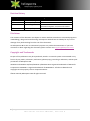
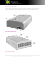
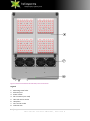
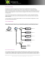
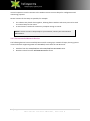
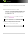
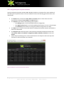
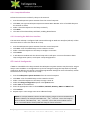
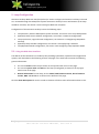
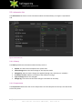
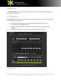
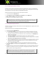
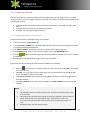
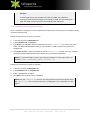
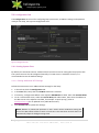
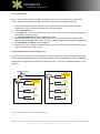
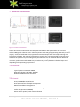
Heliospectra L4A Series 10 User Manual Version 4, 2013-05-24 2|Page L4A Series 10 User Manual, Version 3 Table of Contents 1. About this Document .......................................................................................................................... 6 1.1. Purpose......................................................................................................................................... 6 1.2. Scope ............................................................................................................................................ 6 1.3. Intended Audience ....................................................................................................................... 6 1.4. How to Read this Document ........................................................................................................ 7 1.5. Terminology.................................................................................................................................. 7 2. Welcome to the L4A Series 10 ............................................................................................................ 8 3. Installation ........................................................................................................................................... 9 3.1. Unpacking the L4A Series 10 ........................................................................................................ 9 3.2. L4A Series 10 Overview .............................................................................................................. 10 3.3. Mounting the L4A Series 10 ....................................................................................................... 12 3.4. Network Setup............................................................................................................................ 13 4. Heliospectra System Assistant .......................................................................................................... 15 4.1. Installation .................................................................................................................................. 15 4.2. Using Heliospectra System Assistant.......................................................................................... 16 4.3. Static IP Configuration ................................................................................................................ 17 5. Lamp Configuration ........................................................................................................................... 19 5.1. Using the Web User Interface .................................................................................................... 19 5.2. Information Tab .......................................................................................................................... 20 5.3. Operation Tab............................................................................................................................. 21 5.4. Configuration Tab ....................................................................................................................... 25 6. Maintenance ..................................................................................................................................... 29 6.1. Cleaning ...................................................................................................................................... 29 6.2. Firmware Upgrade...................................................................................................................... 29 7. Technical Specifications..................................................................................................................... 30 7.1. Electrical ..................................................................................................................................... 30 7.2. Control ........................................................................................................................................ 30 7.3. Physical ....................................................................................................................................... 31 7.4. Certification and Safety .............................................................................................................. 31 7.5. Package Contents ....................................................................................................................... 31 8. Warranty Information ....................................................................................................................... 32 3|Page L4A Series 10 User Manual, Version 3 8.1. Equipment Warranty .................................................................................................................. 32 8.2. Software Warranty ..................................................................................................................... 32 8.3. Disclaimers ................................................................................................................................. 32 9. Contact Information .......................................................................................................................... 34 4|Page L4A Series 10 User Manual, Version 3 Revision History Revision/Date 1 / 2011-11-09 2 / 2012-06-01 3 / 2013-03-29 Author Kirk Clendinning Anthony Gilley Jon Solberg 4 / 2013-05-24 Anthony Gilley Changes First version Second version Third version. Reworked document: new document template, structure and content Updates to reflect 2.0.0 firmware release Disclaimer The contents of this document are subject to revision without notice due to continued progress in methodology, design and manufacturing. Heliospectra AB shall have no liability for any error or damage of any kind resulting from the use of this document. At Heliospectra AB we aim to continuously improve our product documentation. If you have comments or ideas regarding this document, please contact us at [email protected]. Copyright and Trademarks No part of this publication may be reproduced, stored in a retrieval system or transmitted in any form or by any means, electronic, mechanical, photocopying, recording or otherwise, without prior permission of Heliospectra AB. Windows and Windows XP/Vista/Windows 7/Windows 8 are registered trademarks of Microsoft Corporation. NETGEAR is a registered trademark of NETGEAR Inc. All other trademarks and copyrights are the property of their respective owners. ©2011–2013 by Heliospectra AB. All rights reserved. 5|Page L4A Series 10 User Manual, Version 3 1. About this Document This document is the Heliospectra L4A Series 10 User Manual. 1.1. Purpose This document provides a full user description of the L4A Series 10. 1.2. Scope This document covers: Introduction to the Heliospectra L4A Series 10, see chapter 2 Welcome to the L4A Series 10 Initial installation, see chapter 3 Installation Heliospectra System Assistant, see chapter 4 Heliospectra System Assistant Lamp configuration, see chapter 5 Lamp Configuration Maintenance and firmware upgrading, see chapter 6 Maintenance Technical specifications, see chapter 7 Technical Specifications Warranty information, see chapter 8 Warranty Information The document is not intended to provide a complete description of all use scenarios possible with the L4A Series 10. 1.3. Intended Audience This document is aimed towards those who wish to setup, configure and use the L4A Series 10 for daily operation. 1.3.1. Prerequisites It is assumed the reader of this document is proficient with: Basic Microsoft Windows® operation and configuration Basic network configuration and troubleshooting To configure the lamp the reader will need a modern and up to date Web Browser. The L4A Series 10 has been tested with Internet Explorer 10, Firefox 20.0.1 and Google Chrome 26.0.1410.64 m. 6|Page L4A Series 10 User Manual, Version 3 1.4. How to Read this Document The typographic conventions used in this document are shown in Table 1 Typographic Conventions: Table 1 Typographic Conventions Format File Names Term GUI Objects Hyperlinks NOTE! Used For File names and paths Example The schedule rows are exported to the file schedule.txt. Terms and concepts, references to sections, chapters and documents, general emphasis Buttons, fields and other GUI objects Links to e-mail and web addresses Notes containing important information The L4A Series 10 can execute and repeat up to 15 light events per day. For information about how to perform a firmware upgrade for a lamp, see section 6.2 Firmware Upgrade. In the web UI, click the Operation tab. Download the latest firmware upgrade package from support section at www.heliospectra.com. NOTE! If unsure of how to setup lamps in your network, contact your local network administrator. 1.5. Terminology The terms and concepts used in this document are shown in Table 2 Terms and Concepts. New terms and concepts are always explained when introduced in the text. However, the reader may find it useful to be familiar with some central terms and concepts beforehand. Table 2 Terms and Concepts Term Cluster Light event Master Schedule Slave Web UI Explanation A cluster is a group of lamps on the same network controlled by a master lamp. A light event is a setting change of one or more of the light channels in the lamp. A master lamp controls one or several slave lamps in a cluster. A schedule is a sequence of light events repeated on a daily basis. A slave is a lamp controlled by a master lamp. The Web User Interface is used for configuring and monitoring a lamp in a network. 7|Page L4A Series 10 User Manual, Version 3 2. Welcome to the L4A Series 10 The Heliospectra L4A Series 10 is a 600W, programmable LED light source for research, teaching and plant growth purposes. The system is an excellent tool for use in plant labs and research greenhouses, including indoor and vertical farms, walk-in chambers and growth cabinets. The L4A Series 10 provides individual regulation of light intensity per wavelength allowing custom spectral distributions (from violet to far-red, max 400-735 nm). It comes complete with a built-in web user interface for easy web-based light configuration, scheduling and monitoring. Figure 1 The Heliospectra L4A Series 10 8|Page L4A Series 10 User Manual, Version 3 3. Installation This chapter covers initial installation of the L4A Series 10. The installation description covers the following areas: Unpacking, see section 3.1 Unpacking the L4A Series 10 Overview of the L4A Series 10, see section 3.2 L4A Series 10 Overview Initial installation; see section 3.3 Mounting the L4A Series 10 Network Setup, see section 3.4 Network Setup 3.1. Unpacking the L4A Series 10 The packing list is included in each shipment. It specifies the part numbers and descriptions of each part in your order. See Table 3 Package List for a listing of the contents of the L4A Series 10 package. Table 3 Package List Description Heliospectra L4A Series 10 lamp unit Eyelet bolt with nut and washer Power cord Ethernet cable Quick start guide Amount 1 2 1 1 1 Before continuing with installation: 1. Verify that all parts in each L4A Series 10 package have been received. 2. If any part is missing, contact your customer service representative. NOTE! When unpacking the L4A Series 10 make sure to have a sturdy surface to work on. Damage to the unit can occur if dropped. 9|Page L4A Series 10 User Manual, Version 3 3.2. L4A Series 10 Overview Figure 2 L4A Series 10 Main Connectors, Figure 3 L4A Series 10 Fan Outlet, and Figure 4 L4A Series 10 Indicator LED and Plates, Fans and Air Intake provides an overview of the L4A Series 10 lamp unit. Figure 2 L4A Series 10 Main Connectors Figure 3 L4A Series 10 Fan Outlet 10 | P a g e L4A Series 10 User Manual, Version 3 Figure 4 L4A Series 10 Indicator LED and Plates, Fans and Air Intake Legend: 1. 2. 3. 4. 5. 6. 7. 8. Mounting screw holes Ethernet port Power socket Wi-Fi antenna (not used) Heat sink and air outlet LED plates Fans and air intake Indicator LED 11 | P a g e L4A Series 10 User Manual, Version 3 3.3. Mounting the L4A Series 10 For proper operation the L4A Series 10 must be mounted horizontally from a support structure. The support structure needs to be sturdy enough to support the weight of lamps and any additional equipment. It must also allow for air to flow freely into the unit (an additional fan duct is available upon request; contact your Heliospectra sales representative for more information). Follow the instructions to mount the L4A Series 10: 1. Fasten the two eye bolts into the mounting screw holes ①; see Figure 2 L4A Series 10 Main Connectors. Use the supplied M6 washers and nuts to tighten the eye bolt screws. Verify that the eye bolt screws go approximately 10 mm into the mounting holes. Do not use excessive force when tightening the screws. 2. Use chains or cables to suspend the lamp levelly from the support structure. 3. If other mounting hardware is used make sure that the bolts go all the way in the mounting holes (10 mm). 4. Verify that the unit is securely fastened. NOTE! Verify that the air outlet ⑤ and intake ⑦ are not covered and that air is allowed to flow freely around the unit. Otherwise, overheating may occur and cause the unit to dim to counteract heat buildup. 5. Connect the supplied Ethernet cable to the Ethernet port ②. 6. Connect the Ethernet cable to a free port on the switch assigned to the cabinet (see Example Setup for more information). 7. To power up the lamp, connect the supplied power cord to the power socket ③, and then connect the cord to a grounded 120V/230V, 50/60Hz power outlet. The lamp will beep twice and the indicator LED ⑧ (see Figure 4 L4A Series 10 Indicator LED and Plates, Fans and Air Intake) will flash orange for approximately 15 seconds and then flash green. The lamp unit is now ready for use. NOTE! If the indicator LED does not flash green after 60 seconds, verify that all cables are securely attached and that the unit and switch are powered on. Also verify that DHCP is enabled in your network. If the problem persists, power cycle the lamp by removing and reinserting the power cable. 8. Repeat steps 1–7 to mount additional lamp units. 12 | P a g e L4A Series 10 User Manual, Version 3 3.4. Network Setup By default, the L4A Series 10 lamp uses the Dynamic Host Configuration Protocol (DHCP) to automatically receive an IP address from a router in the network. This is a commonly available feature in computer networks. The IP address is used when configuring and monitoring the lamp, see chapter 5 Lamp Configuration. A lamp can also be configured to use a static IP, see section 4.3 Static IP Configuration. If it is vital that each lamp always is assigned the same IP address, consider using DHCP and MAC address reservation (refer to your router documentation for more information how to setup static DHCP addresses). If unsure whether your network supports DHCP or if to use static IP address configuration, contact your local network administrator. 3.4.1. Example Setup When setting up several lamp units it is recommended to assign them to a dedicated network. An example lamp network is shown in Figure 5 Network Example Setup, with four lamps per cabinet: Control Control Computer Computer Wireless Router L4A 192.168.1.110 L4A 192.168.1.111 L4A 192.168.1.112 L4A 192.168.1.113 Switch Switch Lamps in cabinet 2 Figure 5 Network Example Setup In the example setup each cabinet is placed some distance apart. Therefore, each set of four lamps are connected to a different switch. Each lamp in the example has been assigned a unique IP address via DHCP in the private 192.168.1.X range. The switches are in turn connected to a wireless router. A 13 | P a g e L4A Series 10 User Manual, Version 3 control computer is used to connect to the wireless router to access lamps for configuration and monitoring purposes. Several variants of this setup are possible, for example: The cabinets are placed close together, allowing fewer switches with more ports to be used to connect lamps to the router. A wired router is used with a stationary computer acting as control. NOTE! If unsure of how to setup lamps in your network, contact your local network administrator. 3.4.2. Recommended Network Devices The following devices have successfully been used for setting up a network of lamps, but any generic router and switch supporting DHCP and 100 Mbit/s works with the L4A Series 10: Switches from the FS105/108/116 and GS105/108/116 NETGEAR® series Wireless routers from the WNR1000 NETGEAR® series 14 | P a g e L4A Series 10 User Manual, Version 3 4. Heliospectra System Assistant The Heliospectra System Assistant is an administrative standalone tool for the L4A Series 10, enabling easy identification of and access to configuration and monitoring functions of individual lamps in the network. The tool is also used for setting static IP to and upgrading lamp firmware. 4.1. Installation Before continuing with the installation of the System Assistant, verify that: Lamps are correctly installed and running on a dedicated network. The control computer is running Microsoft Windows XP/Vista/Windows 7/Windows 8® and is connected to the lamp network. An up to date version of the Java Runtime Environment. During the installation process you may be prompted to upgrade your runtime. Follow the instructions to install the Heliospectra System Assistant on the control computer: 1. Download the Heliospectra System Assistant installation package to the control computer from the support section at www.heliospectra.com. It is recommended to save the installation package to the desktop. NOTE! If the control computer does not have Internet access, download the installation package to another computer and transfer it to the control computer with an USB pen drive. 2. Double-click the installation file downloaded in step 1 to start the installation. 3. Complete the setup by following the on-screen instructions. 4. Verify that the installation was successful by double-clicking on the Heliospectra System Assistant icon on the desktop. The Heliospectra System Assistant should start. NOTE! The Heliospectra System Assistant needs access to the network. Verify that no firewall is blocking traffic to or from the tool. 15 | P a g e L4A Series 10 User Manual, Version 3 4.2. Using Heliospectra System Assistant Figure 6 Heliospectra System Assistant Main Window provides an overview of the main window of the Heliospectra System Assistant. The main window contains the following general functions and information: The Action menu contains the Scan, Blink and Launch actions. These actions are also accessible by clicking the Scan, Blink or Launch buttons. The System menu contains the following menu options: o The Settings option covers lamp blink and scan configuration. o The Update system option is used for updating the firmware in one or several lamps. o The Network option allows for setting the network configuration of a lamp. The Help menu contains version information of Heliospectra System Assistant and where to find more information. The lamp list field shows the lamp on the network with detailed information about each lamp (Name, MAC and IP address, Assignment, Mode, Schedule, Firmware version and Status). Select lamps by selecting one or several check boxes in the lamp list. Select the top-most check box to select all lamps in the network. Figure 6 Heliospectra System Assistant Main Window 16 | P a g e L4A Series 10 User Manual, Version 3 4.2.1. Lamp Identification Follow the instructions to identify a lamp in the network: 1. Start the Heliospectra System Assistant from the control computer. 2. Click Scan; see Figure 6 Heliospectra System Assistant Main Window. A list of available lamps on the network is shown. 3. Select a check box adjacent to the lamp to identify. 4. Click Blink. 5. The LEDs of the selected lamp will blink, enabling identification. 4.2.2. Accessing the Web User Interface The L4A Series 10 lamp is configured and monitored through its Web User Interface (web UI). Follow the instructions to access the web UI for a lamp: 1. 2. 3. 4. 5. Start the Heliospectra System Assistant from the control computer. Click Scan. A list of available lamps on the network is shown. Select a check box adjacent to the lamp to configure or monitor. Click Launch. A web browser window with the chosen lamp web UI will open. For more information about lamp configuration options, see chapter 5 Lamp Configuration. 4.3. Static IP Configuration If DHCP is unavailable in the lamp network the Heliospectra System Assistant may be used to assign a lamp a static IP address. IP configuration may also be changed through the lamp web UI (if already assigned an IP address; see section 5.4.2 Configuring Network Settings for more information). Follow the instructions to assign a static IP to a lamp: 1. 2. 3. 4. 5. 6. 7. 8. Start the Heliospectra System Assistant from the control computer. Click Scan. A list of available lamps on the network is shown. Select a check box adjacent to the lamp to assign a static IP. Select the Change Configuration option in the System menu. Select static in the DHCP field. Enter the appropriate values in the IP address, Netmask, Gateway, DNS1 and DNS2 fields. Click Confirm. Repeat steps 1–10 to assign static IPs to additional lamps. NOTE! For a simple address scheme consider assigning ranges of chosen IP addresses to different cabinets, for example: 192.168.1.110, …111, …112 and …113 to the lamps in the first cabinet, 192.168.1.120, …121, …122 and …123 to the second cabinet and so on. It is recommended to clearly label each lamp for future reference. 17 | P a g e L4A Series 10 User Manual, Version 3 4.3.1. Firmware Upgrade For information about how to perform a firmware upgrade for a lamp, see section 6.2 Firmware Upgrade. 18 | P a g e L4A Series 10 User Manual, Version 3 5. Lamp Configuration L4A Series 10 lamp Web User Interface (web UI) is used to configure and monitor each lamp. The web UI is accessed through the Heliospectra System Assistant or directly from a web browser (if the lamp IP address is known; see section 4.2.2 Accessing the Web User Interface). Configuration of the L4A Series 10 lamp covers the following steps: Lamp discovery with the Heliospectra System Assistant, see section 4.2.1 Lamp Identification (Optional) Lamp static IP address configuration, see section 4.3 Static IP Configuration Lamp system time, tags and name configuration, see section 5.3.1 Configuring Lamp Name and Tags (Optional) Lamp schedule configuration, see section 5.3.3 Configuring a Schedule Lamp Operation Mode Configuration, see section 5.4.3 Configuring Lamp Operation Mode 5.1. Using the Web User Interface The Web UI of the L4A Series 10 is made up tabs providing information, operation and configuration options, each described in the following sections. All pages in the web UI also contain the following general information: The current Status of the lamp is shown on the top left-hand corner of the page. The current System Time and Name of the lamp (if configured) is shown on the top righthand corner of the page. General information for the lamp, such as model, CPU firmware version, driver firmware version, MAC and IP address is shown on the bottom of the page. Click the Show Description link next to a web UI element to find out more information about its use. 19 | P a g e L4A Series 10 User Manual, Version 3 5.2. Information Tab The Information tab shows current information about the selected lamp, see Figure 7 Information Tab. Figure 7 Information Tab 5.2.1. History The History field shows information about the lamp such as: Uptime: The time that has elapsed since system start Latest change: When the latest change to the lamp was made Changed by: How the latest change was applied (through TCP, web client or schedule) IP address of client: Address of the device that made the change Type of change: What was changed? Change log: A text file with the latest changes is fetched from the lamp 5.2.2. Temperature The Temperature field shows the current temperature of each LED plate in the lamp. The L4As Series 10 has four plates. 20 | P a g e L4A Series 10 User Manual, Version 3 5.2.3. LED Status The LED Status field shows the current intensity setting of each LED wavelength in 0-1000 units (0100 % of max LED output). 5.3. Operation Tab The Operation tab is the main tab used for daily work with the L4A Series 10, see Figure 8 Operation Tab. The tab provides functions to: Configure the lamp name and user-defined tags describing the lamp, see section 5.3.1 Configuring Lamp Name and Tags Configure wavelength intensities for the lamp, see section 5.3.2 Setting Wavelength Intensities Configure a schedule for the lamp, see section 5.3.3 Configuring a Schedule Figure 8 Operation Tab 21 | P a g e L4A Series 10 User Manual, Version 3 5.3.1. Configuring Lamp Name and Tags Each lamp can be named and marked with tags for easy identification. Tags are user-defined keys with values that describe lamp specific features (for example, what crop that grows under the lamp, what experiment it is used for, and who is responsible for the lamp). Follow the instructions to add a name and custom tags for the lamp: 1. 2. 3. 4. In the web UI, click the Operation tab. In the Tags field, edit the lamp Name by clicking Edit next to the Name field. Add a tag Key and Value in the respective fields. Repeat step 3 to add additional tags for the lamp. NOTE! The Name tag is a protected key / value pair. Unlike other tags the Name cannot be removed. The value is used as the web UI title and as an identifier when setting up clusters of lamps (see section 5.4.3.2 Master/Slave Configuration). 5.3.2. Setting Wavelength Intensities Individual wavelength intensities of the L4A Series 10 can be independently set. Typically, this is used as part of a schedule. Follow the instructions to set wavelength intensities for the lamp: 1. In the web UI, click the Operation tab. 2. In the Intensities (0-1000) field, set the intensities for the individual wavelengths of the lamp: Use the differently shaded green up and down arrows to increase or decrease wavelength intensities in increments of 1, 10 or 100 units or enter a value directly in the INTENSITY text field for each wavelength. Click All 0 or All 1000 to set all wavelength intensities to 0 or 1000, respectively. Click Add to schedule to add the current wavelength intensities as a light event to a schedule (see section 5.3.3.1 Adding Light Events to a Schedule). Select the Lock ratio check box to lock the ratio between the wavelength intensities. Use this this option when the desired wavelength spectrum is already configured and only overall intensity level need to be changed. Select the Real time update check box for any change to be directly sent to the lamp. 3. If Real Time update is not selected click the Set now button to send the intensities settings to the lamp. 4. The lamp is now set to use the current wavelength intensities. The values will hold until they are changed or a schedule event occurs (see section 5.3.3 Configuring a Schedule). If power to the lamp is cycled the values settings will be lost. NOTE! Lamp intensity should not be dimmed lower than 150 units due to the physical characteristics of LEDs and how they are driven. In the L4A Series 10 the LEDs are driven with constant current and LEDs turn only on above a certain threshold current. 22 | P a g e L4A Series 10 User Manual, Version 3 5.3.3. Configuring a Schedule The L4A Series 10 can execute and repeat up to 150 light events per day. A light event is a setting change of one or more of the light channels in the lamp. For example, a schedule could comprise the following light events: At 07.00, set 400 and 420 nm LEDs to full power (1000 units). Set the 660 nm LED to 500 units. At 11.00, add set the 530 nm LED to 600 units output. At 23.00, turn off all light channels (0 units). 5.3.3.1. Adding Light Events to a Schedule Follow the instructions to add light events to a schedule: 1. In the web UI, click the Operation tab. 2. In the Intensities (1-1000) field, set the desired intensity levels for each wavelength (see section 5.3.2 Setting Wavelength Intensities). 3. Click Add to schedule. The intensity values are copied to the first schedule row. 4. In the Schedule field, enter a start time for the light event in the HH:MM:SS field. 5. Click the button to add the light event to the schedule. A new light event row is added to the schedule. 6. Repeat steps 2–5 to add additional light events to the schedule. Light events can also be edited and removed once added to the schedule: Click the button next to a schedule event row, then confirm by clicking OK in the popup to remove the row. Click Edit next to an event row to update start time and intensities for an individual light event. Click Save to update the settings. Click Delete schedule, then confirm by clicking OK in the popup to remove all light events from the schedule. Click Start schedule to start the current schedule. Click Stop schedule to stop the current schedule. NOTE! The schedule relies on the lamp system time. Verify that the lamp system time is set correctly. The clock in the L4A Series 10 will keep its time up to 48 hours without external power. After 48 hours the clock will be reset. Verify that the clock is set correctly if the lamp has been without power for any significant amount of time. Schedule events override manual events. 23 | P a g e L4A Series 10 User Manual, Version 3 Example: In a lamp light events are scheduled for 1300 and 1400. The schedule is running. At 1315 a manual change to the setting is made. The new setting will hold until 1400 at which time the next schedule event will be set. 5.3.3.2. Exporting and Importing a Schedule Once a schedule is configured, it can be exported and imported to other lamps. This simplifies setting up several lamps quickly. Follow the instructions to export a schedule: 1. In the web UI, click the Operation tab. 2. In the Schedule field, click Export. 3. Click Export. The schedule rows are exported to the file schedule.txt for later use in other lamps. The default download directory for your browser is used as destination path for the schedule file. 4. Click Export to CSV to export a schedule to the file schedule.csv for later use in any software supporting Comma Separated files (for example any spreadsheet application). NOTE! It is recommended to rename the exported schedule to a descriptive name, for example: <DATE>-<EXPERIMENT_NAME>-schedule.txt. Follow the instructions to import a schedule: 1. 2. 3. 4. In the web UI, click the Operation tab. In the Schedule field, click Choose file. Select a schedule file to import. Click Open. The schedule rows are updated. NOTE! Only the schedule.txt file from one lamp can be imported into another lamp. The schedule.csv file is formatted for ease of reading but is not compatible for lamp import. 24 | P a g e L4A Series 10 User Manual, Version 3 5.4. Configuration Tab The Configuration tab is used for configuring lamp system time, IP address settings, and operation mode for the lamp, see Figure 9 Configuration Tab. Figure 9 Configuration Tab 5.4.1. Setting System Time By default, the LA4 Series 10 uses a Network Time Protocol server for setting the lamp system time. The system time can also be configured manually if no NTP server is available. If unsure, it is recommended to use the default settings. 5.4.1.1. Setting Additional NTP Settings Follow the instructions to set additional NTP settings for the lamp: 1. 2. 3. 4. In the web UI, click the Configuration tab. In the Time field, verify that the Use NTP check box is selected. If necessary, configure NTP Offset in the adjacent HH:MM:SS text field. Then click Set NTP Offset. To set a custom NTP server, select the Custom NTP pool radio button, then enter the address to the NTP server in the adjacent text field, for example “se.pool.ntp.org” (refer to www.pool.ntp.org for an updated list of public NTP servers). 5. Click Set NTP Pool to update the settings. NOTE! Without an offset NTP operates on UTC. Under normal conditions setting the hour of the NTP offset suffices to work in local time. The L4A Series 10 clock does not automatically adjust for daylight savings time. 25 | P a g e L4A Series 10 User Manual, Version 3 5.4.1.2. Setting System Time Manually Follow the instructions to set the system time manually: 1. 2. 3. 4. In the web UI, click the Configuration tab. In the Time field, verify that the Use NTP check box is cleared. Enter the current time in the format HH:MM:SS in the field next to the Set Time button. Click Set Time to update the system time. 5.4.2. Configuring Network Settings The network field is used to configure the lamp to use either static or dynamic IP addresses. By default, the lamp is configured to use a dynamic IP address. If unsure, it is recommended to use the default settings. Follow the instructions to setup a static IP address for the lamp: 1. 2. 3. 4. 5. 6. 7. 8. In the web UI, click the Configuration tab. In the Network field, select the Static IP radio button. Enter IP address. Enter Subnet. Enter default Gateway. Enter primary DNS in the DNS1 field. Enter secondary DNS in the DNS2 field. Click Update. 5.4.3. Configuring Lamp Operation Mode The L4A Series 10 lamp can operate in any of the roles and modes described in Table 4 Lamp Roles and Operation Modes: Table 4 Lamp Roles and Operation Modes Role/Mode Schedule driven Manual control Master driven Independent Yes Yes No Master Yes Yes No Slave No No Yes Independent: An independent lamp is controlled through its web UI. Its light intensity settings can either be configured manually or automatically through a schedule. An independent lamp cannot be controlled by another lamp. 26 | P a g e L4A Series 10 User Manual, Version 3 Master: A master lamp controls a cluster of one or several slave lamps either by the use of a schedule or by setting light intensity levels manually in the master lamp web UI. This feature reduces the number of lamps that need to be configured in a fixed lamp installation. Slave: A slave lamp mirrors the change in light output of a master lamp (regardless of whether the master lamp changes are due to schedule events or manual changes). A slave can only be controlled via the master lamp. 5.4.3.1. Independent Configuration By default, the L4A Series 10 Lamp is configured to run in independent mode. If changed, follow the instructions to reset the lamp to independent mode: 1. Start the Heliospectra System Assistant to access the web UI for the lamp to be configured in independent mode (see section 4.2.2 Accessing the Web User Interface). 2. Click the Configuration tab. 3. In the Master/Slave field, select the Independent radio button. The lamp now runs in independent mode. 5.4.3.2. Master/Slave Configuration Configuring a cluster of master and slave lamps involves the following steps: Name and assign a master for the cluster (Optional) Configure a schedule for the master Name and assign slaves to the cluster master Master Configuration Follow the instructions to configure a master lamp: 1. Start the Heliospectra System Assistant to access the web UI for the lamp that should be configured as a master (see section 4.2.2 Accessing the Web User Interface). 2. Click the Operation tab. 3. In the Tags field, enter lamp name and custom tags for the master (see section 5.3.1 Configuring Lamp Name and Tags). 4. (Optional) Configure or import a schedule of light events for the master, see section 5.3.3 Configuring a Schedule. 5. Click the Configuration tab. 6. In the Master/Slave field, select the Master radio button. The master lamp will now inform other lamps on the network that it is a master. All light intensity changes in the master are broadcasted to the network. Other lamps may now tune in and follow the master. NOTE! Several master lamps can be configured in the same network, see section Multiple Master/Slave Cluster Configuration. The master lamp will override any schedule or manual setting of its assigned slave lamps. 27 | P a g e L4A Series 10 User Manual, Version 3 Slave Configuration Once a master lamp has been configured, configure and add one or several slave lamps to the cluster. Follow the instructions to add a slave to a cluster with a preconfigured master: 1. Start the Heliospectra System Assistant to access the web UI for the lamp that should be configured as a slave (see Lamp Configuration and Monitoring). 2. Click the Operation tab. 3. In the Tags field, enter a descriptive lamp name for the slave and custom tags (see Configuring Lamp Name and Custom Tags). 4. In the Master/Slave field select the Slave radio button. 5. Choose which master to use from the drop-down list. If several masters are present in the network choose the applicable master, see section Multiple Master/Slave Cluster Configuration. 6. Click Set Master. The Slave is now configured. 7. Repeat steps 1–6 to configure additional slaves in the cluster. A maximum of eight slave lamps may be controlled by a single master. Multiple Master/Slave Cluster Configuration The master/slave mechanism of the L4A Series 10 allow for dynamic cluster allocation with several master lamps and assigned slaves in the same network. In the example shown in Figure 10 Multiple Master/Slave Configuration Example slave lamps in Cluster 1 and 2 are controlled by Master 1 and Master 2. Wireless Router L4A Switch L4A L4A L4A Master Cluster 1 Switch L4A Slave Cluster 1 Slave Cluster 1 Cabinet 1 L4A L4A Master Cluster 2 Slave Cluster 2 Slave Cluster 2 Slave Cluster 2 Cabinet 2 Figure 10 Multiple Master/Slave Configuration Example 28 | P a g e L4A Series 10 User Manual, Version 3 6. Maintenance The following chapter covers maintenance schedules and practices for the L4A Series 10. It also covers firmware upgrade of the lamp unit. 6.1. Cleaning Clean the L4A Series 10 regularly to ensure proper operation: If the clear plastic plate covering the LEDs becomes dirty it should be wiped off with a soft damp cloth. A mild detergent can be used if the plate has finger prints or similar smudges. Check monthly. If the air inlet or outlets become clogged with dust or large particles they can be carefully vacuumed. Check monthly. NOTE! Do not use any strong detergents on the plastic housing or LED plates. They can be damaged by certain household cleaners or solvents such as kerosene. 6.2. Firmware Upgrade The firmware of the L4A Series 10 is upgraded with the Heliospectra System Assistant. Follow the instructions to perform a firmware upgrade: 1. Check under the support section of www.heliospectra.com if there are any upgrades and how to acquire the upgrade file. 2. Download the upgrade file to the computer running the Heliospectra System Assistant. 3. Start the Heliospectra System Assistant from the control computer on the lamp network. 4. Click Scan to update the lamp list. 5. Select one or several lamps to upgrade from the list. 6. Select System > Update system from the menu. 7. Select the firmware package downloaded in step 1, then click Open. 8. The upgrade will start. A progress bar will show the progress of the firmware upgrade process. 9. Wait until the upgrade process completes. NOTE! Do not turn off the lamp or close the Heliospectra System Assistant during the upgrade process. 10. Click Scan to refresh the lamp list. After an upgrade it takes 10-15 seconds for the lamp to respond. Click Scan an extra time if to refresh the list if the lamp(s) do not show up the first time. 11. Verify that the Firmware column shows the new firmware version number for the updated lamps. 29 | P a g e L4A Series 10 User Manual, Version 3 7. Technical Specifications Figure 11 Technical Specifications Photon flux measured 63 cm from the lamp with OceanOptics JAZ spectrometer in a Conviron Adaptis 1000 growth cabinet at 25°C. Values represent each LED group operating separately at 100 % capacity. Total and Total PAR values represent the maximal output when the lamp is running at its full capacity of 600W. The user has full freedom to regulate the current provided to each LED group therefore the spectrum of produced light may be tailored to suit an individual demand. Maximum irradiance, peak maxima and FWHM may somewhat vary (<2.5%) between individual lamps and depending on the operating temperature. 7.1. Electrical • • • Typical power consumption 600W Operating voltage 120V/230V, 50/60Hz Wieland RST20I3S female connector 7.2. Control • • • • • • RJ 45, 10/100Mbit IPv4 Ethernet HTTP web interface for simple management DHCP for IP address management TCP and UDP for external control and monitoring 32-bit microprocessor (80MHz) Status LED for power/system status indication 30 | P a g e L4A Series 10 User Manual, Version 3 7.3. Physical • • • • • • • • Weight: 13 kg Dimensions: 157 x 385 x 594 mm (height x width x depth) Temperature: Operating -10–40 °C Storage -20–70°C Operation humidity 90 % (max) relative humidity, non-condensing Storage humidity 95 % (max) relative humidity, non-condensing Durable plastic housing Highly light trans missive polycarbonate front cover Ingression protection: IP 23, for indoor use only 7.4. Certification and Safety • • CE marked Risk group 2 certified in accordance with SS-EN 62471 7.5. Package Contents • • • • • Heliospectra L4A Series 10 lamp unit Eyelet bolts with nut and washer 1m power cord with connector 2m Ethernet cable Quick installation guide 31 | P a g e L4A Series 10 User Manual, Version 3 8. Warranty Information The following chapter covers warranty information for: Equipment Software Disclaimers 8.1. Equipment Warranty Heliospectra warrants that for a period of 1 year from the shipment date, the Equipment will be free from defects in material and workmanship under normal use. This limited warranty extends only to the original user of the Product. Equipment support is defined as “Return to Factory” which means the customer is responsible for obtaining an RMA number and shipping the unit to Heliospectra’s principal place for logistics. Heliospectra will either repair and return the original unit or provide a reconditioned unit within 30 days of receipt of the defective unit. The customer is responsible for shipping costs associated with shipping the unit to Heliospectra. Heliospectra will provide for return shipment free of charge (excluding Tax & Duty). The warranty period for the Equipment starts the day it is shipped from Heliospectra. 8.2. Software Warranty Heliospectra warrants that for a period of ninety (90) days from the shipment date, the media on which the software embedded in the Equipment (“Software”) is recorded shall be free from defects in material and workmanship under normal authorized use consistent with the product instructions. This limited warranty extends only to the customer who is the original licensee. In no event does Heliospectra warrant that the Software is error free or that the customer will be able to operate the Software without problems or interruptions. This warranty does not apply if the Software, Product, or any other equipment upon which the Software is authorized to be used (a) has been altered, except by Heliospectra or its authorized representative, (b) has not been installed, operated, repaired, or maintained in accordance with instructions supplied by Heliospectra, (c) has been subjected to abnormal physical or electrical stress, abnormal environmental conditions, misuse, negligence, or accident; or (d) is licensed for beta, evaluation, testing or demonstration purposes. 8.3. Disclaimers To the full extent permitted by law, Heliospectra will not be liable to the customer for any loss or damage arising from the use of the Equipment, or any defect, in the Equipment, however it may arise. 32 | P a g e L4A Series 10 User Manual, Version 3 Apart from the above Equipment and Software warranties, Heliospectra has no obligation to provide support, maintenance, upgrades, modifications or new releases. Heliospectra disclaims all liability and responsibilities pertaining to and arising under this Agreement as a result of Customer integrating, connecting or networking the Equipment in any manner whatsoever. If technical advice or support is given or offered in connection with the use or implementation of the Equipment, it will be solely as an accommodation to the Customer and without charge unless otherwise agreed upon. Heliospectra shall have no responsibilities or liabilities whatsoever for the content or use of such advice. In no event will Heliospectra be liable to Customer or any other person for special, consequential, indirect or incidental loss or damage of any kind or any direct loss or damage of any kind suffered or incurred by the Customer or any other person in connection with the Equipment provided hereunder. THE ABOVE STATE HELIOSPECTRA’S ENTIRE RESPONSIBILITY AND CUSTOMER’S SOLE AND EXCLUSIVE REMEDY WITH RESPECT TO ANY BREACH OF ANY WARRANTY REGARDING THE HARDWARE AND SOFTWARE. HELIOSPECTRA, ON BEHALF OF ITSELF AND ITS AFFILIATES AND SUPPLIERS HEREBY EXPRESSLY DISCLAIMS ALL OTHER WARRANTIES, WHETHER EXPRESS, IMPLIED, OR STATUTORY REGARDING OR RELATING TO THE HARDWARE, DOCUMENTATION, SOFTWARE, MEDIA, OR THE SERVICES FURNISHED OR PROVIDED TO CUSTOMER. HELIOSPECTRA SPECIFICALLY DISCLAIMS ALL IMPLIED WARRANTIES OF MERCHANTABILITY AND FITNESS FOR A PARTICULAR PURPOSE. 33 | P a g e L4A Series 10 User Manual, Version 3 9. Contact Information Heliospectra AB Box 5401 SE-402 29 Göteborg Sweden Visiting & Delivery Address Frans Perssons väg 6 / Delsjömotet SE-412 76 Göteborg Sweden Phone: +46 31 40 67 10 Fax: +46 31 83 37 82 e-mail: [email protected] www.heliospectra.com 34 | P a g e L4A Series 10 User Manual, Version 3 35 | P a g e L4A Series 10 User Manual, Version 3