1
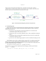
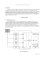
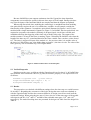
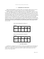
Sixth American Nuclear Society International Topical Meeting on Nuclear Plant Instrumentation, Control, and Human-Machine Interface Technologies
NPIC&HMIT 2009, Knoxville, Tennessee, April 5-9, 2009, on CD-ROM, American Nuclear Society, LaGrange Park, IL (2009)
VERIFICATION OF SAFETY LOGIC DESIGNS BY MODEL CHECKING
Kim Björkman1, Juho Frits2, Janne Valkonen1, Jussi Lahtinen1, Keijo Heljanko2, Ilkka
Niemelä2 and Jari J. Hämäläinen1
1
Technical Research Centre of Finland (VTT)
P.O. Box 1000, FI-02044 VTT, Finland
[email protected]; [email protected]; [email protected]; [email protected]
2
Helsinki University of Technology (TKK)
Department of Information and Computer Science
P.O. Box 5400, FI-02015 TKK, Finland
[email protected]; [email protected]; [email protected]
ABSTRACT
In nuclear power plants, novel digitalized I&C systems have brought out new needs for
safety evaluation. The programmable digital logic controllers enable complicated control
functionalities and, thus, their comprehensive verification is a difficult task. Model checking is a
promising method that enables complete verification of the logic design when a finite state
machine model of the control logic is available. The paper investigates the verification of a power
plant related safety logic system which combines real-time aspects through the use of timers with
control logic. Because of the involved combination a comprehensive and reliable analysis by
manual inspection and testing is challenging. For analyzing the logic design of the system, we
employed two model checking tools. The Uppaal model checker was selected for its good
handling of real time aspects while the NuSMV model checker was selected because it is tailored
for the analysis of large systems. The safety logic system was modeled using NuSMV and Uppaal
and the model checking capabilities of the systems were studied by analyzing whether the key
requirements for safety are satisfied. Then three increasingly challenging failure models were
created for NuSMV to check the fulfillment of the single failure criterion. The analysis clearly
demonstrates the benefits of model checking in the verification and licensing of digital
automation. The analysis also demonstrates strengths and limitations of the two model checking
tools.
Key Words: safety logic, digital I&C, model checking, verification, automation
1
INTRODUCTION
In nuclear power plants (NPPs), novel digitalized I&C systems enable complicated control
tasks which create new challenges for safety evaluation. However, validation of safety logic
designs still relies heavily on subjective evaluation that covers only a limited part of the possible
behaviors. Formal methods are available (see, for example, [10] for an overview) but often they
are only used for certain tasks as indicators of possible problems. Model checking [6] is a
promising formal method that, at least theoretically, enables complete verification of the desired
properties, which is typically not possible with traditional simulation methods. A detailed
dynamic model of the process and automation can be utilized in simulation-based analysis, but in
most cases it cannot be used for verifying the correct system behavior covering all possible
Björkman et al.
situations. Model checking is based on a so-called state machine model of the logic and the
essential surrounding systems. A number of efficient model checking systems have been
developed offering analysis tools which are able to determine automatically whether a given
state machine model satisfies desired safety properties for realistic designs. See [11]
demonstrating the use of model checking on two NPP-related case studies. Model checking can
also handle delays and other time-related operations, which are crucial in safety I&C systems
and are challenging to design and verify.
This paper describes the use of two model checking tools, NuSMV [8] and Uppaal [9], for
the verification of a power plant related safety logic system. The capacity and scalability of the
tools are compared using two alternative versions of the example logic that, at first sight, seem to
have identical behavior. However, verification by model checking reveals a hidden design error
in one of the designs that would be difficult to find by manual inspection. In addition to verifying
the correct behavior of the design, the fulfillment of the single failure criterion is verified by
model checking.
2
MODEL CHECKING
Model checking [6] is a computer aided verification method developed to formally verify
the correct functioning of a system design model against its formal specification. Typically, some
variant of state machines are used to model the system, while the specifications are formalized
with temporal logics. Efficient model checking algorithms employed in model checking tools
(see, e.g., [3]) are used to verify whether all the behaviors of the system model satisfy their
specification given in temporal logic. In case the specification is violated, the model checking
tools help debugging the system by creating a counterexample, an execution of the system model
violating the property. In this work, we employ two different model checking tools, Uppaal [9]
and NuSMV [8], to formally verify properties of safety logic designs.
2.1 Uppaal Model Checker
Uppaal [9] is a model checking tool for timed systems based on modeling the system as a
network of timed automata that communicate through message channels and shared variables.
The timed automata have a finite control structure and real-valued clocks [1, 7]. Networks of
timed automata can express the real-time behavior of the system in continuous time but can still
be automatically analyzed. This is possible because a finite graph induced by the behavior of the
system exists where different clock valuations with, intuitively, the same behavior are grouped
into a finite number of equivalence classes called regions [1]. The model checking algorithms
employed inside Uppaal [7] are able to check a subset of the temporal logic TCTL (Timed
Computation Tree Logic) [2] by explicit state model checking that explicitly traverses the finite
graph induced by the behavior of the system. The main strength of Uppaal is in analyzing
complex timing behavior of a system but it is not too well suited with systems with a very high
amount of non-determinism as induced by e.g., reading a large number of input variables (sensor
readings) provided by the environment, because each combination of inputs is explicitly
explored by the used model checking algorithms.
Page 2 of 12
Verification of Safety Logic Designs by Model Checking
2.2 NuSMV Model Checker
NuSMV [8, 5] is a state-of-the-art symbolic model checker that supports synchronous state
machine models where the real-time behavior has to be modeled with discrete time steps using
explicit counter variables. NuSMV supports model checking using the Linear Temporal Logic
(LTL) and Computation Tree Logic (CTL) [6]. The model checking algorithms employed in this
work are based on symbolically representing and exploring the state space of the system by using
Binary Decision Diagrams (BDDs) [4, 6]. In addition, SAT (propositional satisfiability) based
bounded model checking is also supported by NuSMV [3] for finding bugs in larger designs.
The sophisticated model checking techniques used by NuSMV can handle non-determinism
induced by free input variables well but modeling the real-time aspects can be more challenging
due to the discrete time nature of the synchronous state machine model employed by NuSMV.
3
DESCRIPTION OF THE SYSTEM
The safety-related system analyzed in the research is called the stepwise shutdown logic. It
is used for stepwise control of the process towards the normal operating state in case of
disturbances. The system is triggered if some of the process variables, for example the
measurement of the reactor temperature, deviate from the values set for normal operation. The
purpose of the system is to reduce the possibility that the process enters a state where the actual
shutdown function of the process is needed. The stepwise shutdown logic is a softer way to
control the process and provides savings in time and cost compared with the actual shutdown.
Both shutdown systems use partly the same process variables but in the stepwise shutdown the
limit values are reached earlier.
The stepwise shutdown system is a two-redundant system with respect to its input signals.
Besides providing signal values (analogue and binary), the underlying platform allows also to
process information of the validity of the signals. The used signal validity information is the fault
status, which enables the identification of faulty signals, and processing of faulty signals
according to predetermined rules. For example, if all signals of the same measurement have the
fault status on, the default value of the output of a process variable measurement is zero.
Figures 1 and 2 illustrate two alternative logic diagrams, A and B, that have been designed
for implementing the stepwise shutdown. The stepwise shutdown is performed when the
measurements of the process variables reach and remain a certain period over the releasing limit
values. The process is driven towards a safer state for 3 seconds. After that, there is a delay of 12
seconds (the time left of the 15 s time pulse block after the 3 second control). If the criteria for
the stepwise shutdown are still valid after the delay, the process is afresh driven towards a safer
state for 3 seconds. This is repeated until the process is back in the safe state or completely shut
down (or the actual shutdown is triggered). During the 12 second delay, the following 3 second
control can be accelerated through a manual trip from the control room.
Both alternative designs try to realize the same functionality. The main difference is how
they manage the manual trip from the control room. In design A, the 12 second delay is
interrupted by resetting the time pulse block, thus, hastening the following control. As for the
time pulse blocks, the reset is triggered by a rising edge. In design B, the 3s time pulse block of
the manual trip is directly connected to the output and there are no resettable delays.
Page 3 of 12
Björkman et al.
Figure 1. Stepwise shutdown system, design A
Figure 2. Stepwise shutdown system, design B
Page 4 of 12
Verification of Safety Logic Designs by Model Checking
4
UPPAAL MODEL
4.1 Timed Automaton
A timed automaton [1] is a finite state automaton extended with real-valued clock variables.
The clocks are increased at the same rate and they can be reset in transitions of the automaton.
The edges of a timed automaton can have guard constraints which have to evaluate to true in
order to the transition to be enabled.
In Uppaal's modeling language [7], automata can synchronize with each other over channels.
An edge of an automaton can be declared to send or receive synchronization. Two automata can
synchronize through a binary synchronization channel and then the automata participating in the
binary synchronization must fire the corresponding edges simultaneously. Broadcast channels
allow many receiving edges to participate in the synchronization.
4.2 Modeling the System
Two Uppaal models were created based on the designs A and B in Figures 1 and 2. All input
signals were modeled as Boolean variables. No assumptions about the environment of the system
were made and the input signals were allowed to have non-deterministically any value at any
given moment.
In the Uppaal models, there is an automaton for each of the timer components and an
automaton taking care of input sampling assigning values for the input variables nondeterministically. Hence, the Uppaal model for design A consists of four timed automata. The
model of design B has one additional automaton because of the third time pulse block for the
manual trip signals. The signal logic of the system is modeled as part of those automata as guard
constraints of the corresponding edges.
The automata synchronize with each other through channels. Processes send synchronization
events to a channel to inform other automata about important events, for example the change of a
signal state. The models also have global variables for communication. Such variables can be
used in the guards.
Figure 3 shows a timer automaton modeling the functioning of the pulse block for delay
time units generating the output of the system where the parameter delay is set to 3 (seconds).
The automaton has three locations: initial location Out0, committed location Trigger, and
location Out1. The automaton transfers from location Out0 to location Trigger if it receives
synchronization from channel T2_change or channel input_change and the corresponding guard
evaluates to true. These transitions mean that the input of the timer block has changed from 0 to
1. The automaton receives synchronization from channel T2_change only when there is a falling
edge in the output of the time pulse block of 15 seconds. Respectively, the input_change
synchronization is only sent in case of rising edge of the output of the OR gate. The guard
constraints of those transitions model the other input of the AND block not taking part in the
synchronization. The channels T2_change and input_change are declared as broadcast channels
where synchronization is required only if the corresponding guard holds.
Uppaal supports committed locations which do not allow time to pass and can be used to
model instantaneous state changes in control. In Figure 3, such a construct is used in the location
Page 5 of 12
Björkman et al.
Trigger where the automaton immediately takes a transition to location Out1 sending a
synchronization to channel output_change and resetting the clock variable d. After delay time
units have passed, the automaton takes a transition back to Out0.
Figure 3. Timed automaton modeling time pulse block of delay time units
4.3 Verified Properties
Each of the two models was checked against four properties that formalize a specification
stating that each of the process variable measurements should trigger the stepwise shutdown
system. The properties are:
1. If at least two of the temperature measurement signals are over the limit, then
eventually the output of the system gets value 1.
2. If at least one of the over pressure signals has value 1, then eventually the output gets
value 1.
3. If at least one of the two water inflow signals has been on at least five seconds, then
eventually the output gets value 1.
4. If at least one of the manual trigger signals is on, then eventually the output gets value
1.
In all properties, there is also a condition that the output of the 15 seconds time pulse block
must be zero. This ensures that the input signal gets detected by the time pulse block of three
seconds. The properties can be formalized with TCTL [2]. For example, the second property can
be captured by the following TCTL formula:
A (((In.P121 or In.P221) and T2_out == 0) imply A T1.Out1) .
This formula was expressed in the Uppaal specification language with the special leads-to
operator “-->” as follows:
((In.P121 or In.P221) and T2_out == 0) --> T1.Out1.
Page 6 of 12
Verification of Safety Logic Designs by Model Checking
4.4 Results
A design error of logic design A was found in verification of the system model with Uppaal.
The design error causes the output of the system to freeze to zero value if the manual trip
pushbutton is pushed during the 3 second time pulse. Then the 15 second block is reset and the 3
second block will not receive a rising edge ever again. This feature of design A causes the
violation of all the four checked properties. Design B was found to operate correctly with respect
to the four properties. The model checking times are presented for design A in Table I and for
design B in Table II in Section 6.
5
NUSMV MODEL
5.1 Modeling the System
Two NuSMV models of the stepwise shutdown system were built based on the logic
diagrams presented in Figures 1 and 2. Both models were divided into several sub-modules
according to Figure 4 below. The basic function blocks were modeled as individual modules to
improve component reusability. Each sub-module contained the input signals and their
processing and voting logics for a particular process variable measurement. The environment
was allowed to behave as freely as possible, i.e., the input signals were allowed to get any value
at any given moment.
Figure 4. Module division
Page 7 of 12
Björkman et al.
Because NuSMV does not support continuous time like Uppaal, the time dependent
components were modeled to operate in discrete time steps of fixed length. During each time
step, first the inputs of the functional blocks are sampled and then the outputs are updated.
When using discretized time, modeling the control logic is straightforward but modeling
time pulse blocks requires the use of so-called timer variables. As an example consider the
functionality of the rightmost 3 second time pulse block illustrated in Figures 1 and 2. It was
modeled with a single automaton in Uppaal (see Figure 3). In NuSMV, the time pulse block was
captured as a separate code module consisting of an input signal, a local timer variable and
conditions allowing the triggering of the timer only with the rising edge. The output of the
module remains 1 as long as the timer is running. Figure 5 illustrates the NuSMV code when the
length of the time step is 1 second and therefore the timer variable Timer can have values from 0
to 3. The timer is triggered if input of the module is 1, the previous value is 0, and the value of
the timer is 0. When timer gets value higher than or equal to 3, the timer is reset. The value of the
timer grows by one at each time step, if it is higher than 0.
Figure 5. NuSMV model of the 3 second time pulse
5.2 Verified Properties
Similar properties were verified as with the Uppaal model (see Section 4.3). In NuSMV, the
specifications were formalized with LTL [6] and, for instance, property 2 was expressed in LTL
as follows:
LTLSPEC G(((press.I121 | press.I221)&
stepwiseshutdown.tp2.output = 0) ->
F(stepwiseshutdown.Output));
5.3 Results
The properties were checked with different settings where the time step was varied between
10 ms and 1 s. Regarding the correctness of the logics design the same result was obtained as
with the Uppaal models and also the erroneous behavior of design A was discovered in all the
considered settings. When using the time step of 10 ms, the size of the state space of the models
of designs A and B is 3·1015 and 1018 and that of the reachable state space 2·1012 and 4·1014
respectively. The model checking times are presented for design A in Table I and for design B in
Table II.
Page 8 of 12
Verification of Safety Logic Designs by Model Checking
6
COMPARISON OF RESULTS
Both Uppaal and NuSMV revealed the design error causing the output to freeze to zero in
logic design A. Design B was found to operate correctly according to the specification.
Model checking was carried out with Uppaal version 4.0.6 and NuSMV version 2.4.3 on a
PC with 2 GB of RAM and Intel Core 2 Duo E6320 processor running at 1.86 GHz. The model
checking times of the verification runs for Uppaal and NuSMV (with 3 different time steps) are
presented in Tables I and II. The model checking times of Uppaal models were between 9 and 21
seconds and NuSMV models between 1 and 31 seconds. In most cases, the model checking times
of property 3 were the longest due to the 5 second delay element related to the water inflow
signals (see Figures 1 and 2). Except for property 3, the model checking times of design B with
Uppaal were about two times longer than those of design A. This is because the error in design A
caused the properties to be violated and, thus, the model checker did not have to go through the
whole state space of the model. In NuSMV, the model checking times of both designs were of
the same order.
Table I. Model checking times for design A (s)
Design A
Property
Uppaal
Property 1
Property 2
Property 3
Property 4
9.1
9.1
20.6
9.1
NuSMV
1s
100 ms 10 ms
0.6
1.6
7.1
0.6
1.6
7.2
0.6
1.4
16.4
0.6
1.6
6.1
Table II. Model checking times for design B (s)
Design B
Property
Uppaal
Property 1
Property 2
Property 3
Property 4
17.7
18.0
17.7
17.6
7
NuSMV
1s
100 ms 10 ms
0.3
1.2
7.7
0.3
1.2
7.6
0.6
1.5
30.4
0.3
0.8
7.0
FAILURE MODELS
In addition to verifying the correct behavior of the stepwise shutdown logic (design B), the
fulfillment of a single failure criterion was analyzed with the NuSMV model. Given a failure
model, such a criterion means that a system must be capable of performing its task in the
presence of any single failure.
Page 9 of 12
Björkman et al.
In failure models we assume that a failure can only affect one input signal of each process
variable measurement at a time and that the logical components function correctly. Different
failures were classified according to their effect and diagnostic perceptivity.
The following three models were considered:
1. All failures are detected, failed input signals get a non-deterministic value, and input
signals may fail or recover at any time step.
2. Failures may remain undetected, failed input signals keep their previous values, and
input signals may fail or recover at any time step.
3. Failures may remain undetected, failed input signals get a non-deterministic value,
and input signals may fail or recover at any time step.
Each measurement was given an additional Boolean variable for representing the fault
status. The following properties were checked:
1. A single failure should not spuriously trigger the stepwise shutdown.
2. A single failure should not prevent the actual execution of the stepwise shutdown.
Design B fulfilled both of the single failure criterion properties completely with failure
models 1 and 2. With failure model 3, the design did not fulfill the property 1 because a single
undetected faulty binary signal with value 1 could spuriously trigger the stepwise shutdown
system. As the design is two-redundant based on 1 out of 2 voting, this property cannot even be
expected to be fulfilled. However, in this case, the system fails in the safe direction. With failure
model 3, design B fulfills property 2, i.e., no failures with dangerous consequences were
discovered.
The introduction of the failure models increased the size of the state space. When using the
time step of 10 ms, the state space of design B was 3·1022 and the model checking times were
between 1 and 70 seconds. The longest model checking times were measured for property 1 with
failure model 3 when the time step was 10 ms.
8
CONCLUSIONS
Modern digitalized I&C systems include more and more complicated control tasks. Such
systems often combine real-time aspects such as timers with non-trivial control logic making
their design and validation very challenging. Model checking is a promising formal method that
enables complete verification of designs of such systems. Design verification is a key task in the
design flow because it can eliminate tricky design errors which are hard to detect later in the
development process and are very expensive to repair leading often to a major redesign and
reimplementation cycle. Model checking requires a state machine model of the design and its
relevant environment. It seems to lend itself well to verification of safety logic designs because
forming a state machine model of such a design is often quite unproblematic.
In this paper we studied the use of two types of model checking approaches to verifying
safety logic designs involving timing aspects. One approach is to use timed automata as the
modeling framework and the other is to employ finite state machines typically used in verifying
hardware. For the former approach we used the Uppaal model checking system and for the latter
NuSMV. The approaches were compared using two similar designs of a safety logic
Page 10 of 12
Verification of Safety Logic Designs by Model Checking
demonstrating clearly how small subtle changes in design lead to unexpected errors which are
hard to detect without exhaustive model checking techniques. We developed a straightforward
approach to modeling such designs using timed automata and finite state machines and studied
the performance of the model checking tools when verifying safety requirements of the designs.
Uppaal allows direct modeling of timers using real-valued clock variables in timed automata
so that also the control logic is easy to capture. However, the analysis techniques in Uppaal are
based on state space enumeration techniques which scale poorly when the number of input
variables in the model grows. NuSMV is well-suited for handling control logic but modeling
time dependent components is less straightforward as such components need to be modeled
operating in discrete time steps. However, the symbolic model checking techniques used in
NuSMV scale much better as the number of input variables grows. Both approaches are able to
verify moderate size designs indicating that current model checking techniques are already
applicable to verifying involved safety logic designs. However, the challenge in validating such
safety logics is the combination of timing aspects with control logic in a setting where
requirements need to be verified in all possible combinations of a large number of input
variables. For such more involved designs, new techniques combining the strengths of timedautomata based modeling and symbolic model checking techniques are needed.
It was shown that it is possible to determine the fulfillment of single failure criteria. Even a
case when the input signals were allowed to fail arbitrarily at any time step could be checked.
The results show that model checking has potential to become a valuable tool that can be used
both in the design and licensing of safety automation.
9
REFERENCES
1. R. Alur and D. L. Dill, “A theory of timed automata”. Theoretical Computer Science, 126(2):
pp.183–235, (1994).
2. R. Alur, C. Courcoubetis, and D. L. Dill, “Model-checking for real-time systems”. Fifth
Annual IEEE Symposium on Logic in Computer Science, Philadelphia, Pennsylvania, June 47 1990. IEEE Computer Society Press. pp. 414-425 (1990).
3. A. Biere, K. Heljanko, T. Junttila, T. Latvala, and V. Schuppan, “Linear Encodings of
Bounded LTL Model Checking”, Logical Methods in Computer Science 2(5:5):1-64, 2006
4. R. E. Bryant, “Graph-Based Algorithms for Boolean Function Manipulation”. IEEE Trans.
Computers 35(8): 677-691 (1986).
5. R. Cavada, A. Cimatti, C. A. Jochim, G. Keighren, E. Olivetti, M. Pistore, M. Roveri, and A.
Tchaltsev, “NuSMV 2.4 User Manual”, ITC-IRST, http://nusmv.irst.itc.it/ (2009).
6. E. M. Clarke, Jr., O. Grumberg, and D. A. Peled, Model Checking, The MIT Press, (1999).
7. K. G. Larsen, P. Pettersson, and W. Yi, “Uppaal in a nutshell”. International Journal on
Software Tools for Technology Transfer, 1(1-2):134-152, (1997).
8. NuSMV Model Checker v.2.4.3. http://nusmv.irst.itc.it/ (2009).
9. Uppaal integrated tool environment v. 4.0.6, http://www.uppaal.com/ (2009).
10. J. Valkonen, I. Karanta, M. Koskimies, K. Heljanko, I. Niemelä, D. Sheridan, R. E.
Bloomfield, “NPP Safety Automation Systems Analysis - State of the Art”, VTT Working
Page 11 of 12
Björkman et al.
Papers 94, VTT Technical Research Centre of Finland, Espoo, Finland, April 2008, 62 p.
(2008).
11. J. Valkonen, M. Koskimies, V. Pettersson, K. Heljanko, J.-E. Holmberg, I. Niemelä, and J. J.
Hämäläinen, “Formal verification of safety I&C system designs: Two nuclear power plant
related applications”, Enlarged Halden Programme Group Meeting - Proceedings of the
Man-Technology-Organisation Sessions, C4.2., Institutt for Energiteknikk, Halden, Norway,
(2008).
Page 12 of 12