1
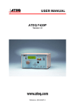
USER MANUAL
ATEQ D520
Version 1.32
Reference: UM-22100F-U
REVISION OF THE D520 USER MANUAL
Edition/
Revision
First edition
Second edition
Reference
Date
(week/year)
Chapters updated
UM-22100A-U
22/2003
-----
10/2004
All chapters. Evolution of the programme
from the 1.00 to 1.10 version. Integration
of two capillaries. Addition of the "Single
CAL" and "No negative" functions, version
"High precision".
UM-22100B-U
Third edition
UM-22100C-U
41/2004
Evolution of the program version from the
1.10 to the 1.20. Add "High precision"
function, electronic regulator instruction
recover function and pressure filtering.
Fourth edition
UM-22100D-U
08/2005
Evolution to the 1.21 version: gas version
(option).
Fifth edition
UM-22100E-U
38/2009
Evolutions to the 1.32 version, add the
"Sequence" function, add bar code option
and add flow regulation function.
Sixth edition
UM-22100F-U
47/2009
Preamble: add 1 l/h and 80 l/h capillary,
correction of the principle scheme for the
indirect measurement (recovery).
Recommendations for leak testing
instruments
Precautions for the test environment
• Keep the test area as clean as possible.
Precautions for the operators
• ATEQ recommends that the operators using the instruments should have a
suitable qualification and training with respect to the work bench requirements.
General precautions
• Read the user manual before using the instrument,
• all electrical connections to the instrument must be equipped with a safety
system (fuse, circuit breaker…) appropriate to its needs and complying with the
standards,
• to avoid electromagnetic interference, the cable connections to the instrument
should be less than two meters in length,
•
it is essential that the electrical main is earthed,
• disconnect the electrical connections to the equipment before maintenance,
• cut the air supply for any kinds of operation on the pneumatic assembly,
• do not open the instrument when it is powered up,
• avoid water spillage near of the instrument,
• ATEQ is at your disposal for any further information concerning the use of the
instrument under maximum safety conditions.
We would like to bring to your attention that ATEQ will not be held responsible
for any accident connected to the improper use of the instrument, to the work
bench or to the lack of compliance with safety rules.
ATEQ Company is free from any responsibility for any adjustment of its
instrument which would not have been done by its own technicians.
The ATEQ cannot be held responsible if the instrument (program, mechanics or
electronics) has been modified without prior written consent.
0039/Ret-U
ATEQ, THE ASSURANCE OF A COMPETENT AFTER SALES
SERVICE
THE ATEQ AFTER SALES SERVICE IS :
• a team of qualified technicians,
• a permanent telephone assistance,
• agencies close to you for faster reaction,
• a stock of spare parts available immediately,
• a car fleet for rapid intervention,
• a commitment to quality ...
THE OVERHAUL
ATEQ carries out the overhaul of your instruments at interesting prices.
The overhaul corresponds to the maintenance of the instrument (checking, cleaning, replacing of used
parts) as part of preventive maintenance.
Preventive maintenance is the best way to guarantee reliability and efficiency. It allows the
maintenance of a group of instruments in good operational order and prevent eventual break-downs.
MAINTENANCE KITS
The ATEQ After Sales Service proposes, two kits destined for the preventive maintenance of the
pneumatic circuits of instruments.
CALIBRATION
This may be carried out on site or in our offices.
ATEQ is attached to the COFRAC and delivers a certificate following a calibration.
TRAINING COURSES
In the framework of partnership with our customers, ATEQ offers two types of training in order to
optimise the usage and knowledge of our instruments. They are aimed at different levels of technician:
• method / control training,
• maintenance / upkeep training.
A TARGETED TECHNICAL DOCUMENTATION
A number of technical documents are at your disposal to allow you to intervene rapidly in the event
minor breakdowns:
• problem sheets describing and offering solutions to the main pneumatic and electronic
problems,
• several maintenance manuals.
A QUALITY GUARANTEE
The instruments are guaranteed for parts and labour in our offices:
• 2 years for leak detection equipment,
• 1 year for electrical tests to norms instruments,
• 1 year for the accessories.
Our After Sales Service is capable of rapidly answering all your needs and queries.
We strongly recommend to send the instrument
back to ATEQ once a year for re-calibration
SAV-Uc/0650
PREFACE
Dear Customer,
You have just purchased an ATEQ instrument, we thank you for the trust you have
placed on our brand. This instrument has been designed to ensure a long and
unparalleled life expectancy, and we are convinced that it will give you complete
satisfaction during many long years of operation.
In order to maximise the life expectancy and reliability of your ATEQ instrument, we
recommend that you install this instrument on a secured workbench and advise you to
consult this manual in order to familiarise yourself with the functions and capabilities of
the instrument.
Our ATEQ After Sales Service centre can give you recommendations based on your
specific operation requirements.
ATEQ
0650/PREFd-U
Table of contents
TABLE OF CONTENTS
PREAMBLE
5
1. DEFINITION OF THE ATEQ D520 ......................................................................................................5
2. CHARACTERISTCS OF THE MEASUREMENT ................................................................................6
2.1. Pressure drop measurement........................................................................................................6
2.2. Test pressure measurement ........................................................................................................6
2.3. Mechanical pressure regulation ...................................................................................................6
3. THE DIFFERENT MEASUREMENT PRINCIPLES .............................................................................7
3.1. Direct measurement.....................................................................................................................7
3.2. Indirect measurement (or recovery mode)...................................................................................8
4. PRESSURE, TEMPERATURE & VISCOSITY EFFECT ON THE MEASUREMENT .........................9
4.1. Pressure variation ........................................................................................................................9
4.2. Viscosity and temperature variation .............................................................................................9
5. CALIBRATION...................................................................................................................................10
5.1. Factory calibration......................................................................................................................10
5.2. Manual calibration ......................................................................................................................10
6. PRINCIPLE OF A CYCLE .................................................................................................................11
7. PRESENTATION OF THE SYMBOLS ..............................................................................................12
Chapter 1
INSTALLATION OF THE INSTRUMENT
1. PRESENTATION OF THE ATEQ D520 ............................................................................................15
2. INSTALLATION OF THE INSTRUMENT ..........................................................................................16
2.1. Presentation of the connectors on the case of the D520...........................................................16
2.2. Connector details .......................................................................................................................17
Chapter 2
USER INTERFACES
1. PRESENTATION OF THE FRONT PANEL OF THE D520 ..............................................................27
2. PRESENTATION OF THE KEYBOARD KEYS ................................................................................28
2.1. Navigation keys ..........................................................................................................................28
2.2. Cycle keys ..................................................................................................................................29
3. KEY LOCK .........................................................................................................................................29
4. REGULATOR.....................................................................................................................................30
5. INFRA-RED INTERFACE ..................................................................................................................30
6. 4 LINE LCD DISPLAY .......................................................................................................................30
7. QUICK CONNECTOR........................................................................................................................30
8. FUNCTIONNALITY OF THE INDICATORS ......................................................................................31
Chapter 3
STARTUP AND ADJUSTMENTS
1. POWERING UP THE ATEQ D520 ....................................................................................................33
2. CREATION OF A TEST PROGRAM.................................................................................................34
2.1. Choice of the program number ..................................................................................................34
2.2. Selection of the test type............................................................................................................35
2.3. Adjustment of the parameters ....................................................................................................36
3. COPYING A TEST PROGRAM .........................................................................................................40
4. DELETING A PROGRAM OR THE NAME OF A PROGRAM..........................................................42
5. LAUNCHING OF A CYCLE ...............................................................................................................43
5.1. Choice of the program number to be launched..........................................................................43
5.2. Setting the test pressure ............................................................................................................44
6. STARTING A MEASUREMENT CYCLE...........................................................................................45
7. STOPPING A CYCLE ........................................................................................................................45
UM-22100F-U
User manual ATEQ D520 Page 1/122
Table of contents
Chapter 4
FUNCTIONS OF THE INSTRUMENT
1. MENU STRUCTURE..........................................................................................................................47
1.1. Main menu..................................................................................................................................47
1.2. "FUNCTIONS" menu when activated.........................................................................................52
2. CONFIGURATION MENU .................................................................................................................55
2.1. Extended menus ........................................................................................................................55
2.2. Automatic save...........................................................................................................................72
2.3. Program sequences ...................................................................................................................73
2.4. Ready status ..............................................................................................................................76
2.5. Reference cal .............................................................................................................................76
2.6. Bar Graph...................................................................................................................................76
2.7. Hour............................................................................................................................................77
2.8. Regulator learning......................................................................................................................77
2.9. RS232 ........................................................................................................................................78
2.10. RS485 ......................................................................................................................................81
2.11. Modbus.....................................................................................................................................81
2.12. Security ....................................................................................................................................81
2.13. Lighting the screen...................................................................................................................82
2.14. Bar code (option)......................................................................................................................83
2.15. I/O configuration.......................................................................................................................85
2.16. Remote control.........................................................................................................................86
3. SPECIAL CYCLES MENU.................................................................................................................87
3.1. Special cycles available .............................................................................................................87
3.2. Regulator....................................................................................................................................88
3.3. Calculation of the automatic thresholds .....................................................................................89
3.4. Infinite fill ....................................................................................................................................91
3.5. Piezo reset (auto zero)...............................................................................................................92
3.6. Manual calibration ......................................................................................................................93
3.7. ATR learning ..............................................................................................................................96
4. SERVICE MENU ................................................................................................................................97
4.1. Servicing of the parameters .......................................................................................................97
4.2. Servicing of the sensors.............................................................................................................98
5. RESULTS MENU ...............................................................................................................................99
6. LANGUAGE MENU ...........................................................................................................................99
7. STAND-BY MENU .............................................................................................................................99
7.1. Standby using the menu ..........................................................................................................100
Chapter 5
ACCESSORIES
1. ACCESSORIES SUPPLIED WITH THE INSTRUMENT.................................................................101
1.1. Power supply............................................................................................................................101
2. OPTIONAL ACCESSORIES............................................................................................................102
2.1. Flow master leaks ....................................................................................................................102
2.2. Needle valve and leak flow calibrator ......................................................................................103
2.3. Automatic connectors with expandable joints ..........................................................................104
2.4. Filtration kit ...............................................................................................................................104
2.5. Remote controls .......................................................................................................................105
2.6. Remote front panel RC5 ..........................................................................................................106
2.7. Intelligent remote control..........................................................................................................108
2.8. External cutting valve ...............................................................................................................110
Chapter 6
ERROR MESSAGES
ERROR MESSAGES .................................................................................................. 111
UM-22100F-U
User manual ATEQ D520 Page 2/122
Table of contents
Chapter 7
OPERATIONAL PROBLEMS
1. PHENOMENON NOTED..................................................................................................................113
1.1. Condition of the machine's seals .............................................................................................113
1.2. Damaged instrument seals ......................................................................................................113
1.3. Bumper pad..............................................................................................................................113
1.4. Pneumatic Link.........................................................................................................................113
1.5. Environment .............................................................................................................................114
1.6. Calibration ................................................................................................................................114
1.7. Concerns about reliability of the instrument’s circuits ..............................................................114
Appendices
ATEQ D520
1. TECHNICAL CHARACTERISTICS OF THE D520 .........................................................................115
2. DIMENSIONS OF THE D520...........................................................................................................116
3. CONVERSION TABLE ....................................................................................................................117
4. PARAMETERS SAVED...................................................................................................................118
5. VALVE CODES USED IN YOUR APPLICATION ...........................................................................119
6. PERSONAL NOTES ........................................................................................................................120
Index
UM-22100F-U
121
User manual ATEQ D520 Page 3/122
Table of contents
UM-22100F-U
User manual ATEQ D520 Page 4/122
Preamble
PREAMBLE
1. DEFINITION OF THE ATEQ D520
The ATEQ D520 is a flow meter which measures a drop in pressure with a differential
sensor (transducer) which is placed at the extremities of a calibrated flow tube.
Absolute pressure
sensor
Caloibrated flow tube
Regulator
Dp
Atmosphere
Air pressure
supply
Flow
Test part
Differential
pressure sensor
When fluid (gas) moves through a calibrated flow tube (laminar flow), a drop in pressure
occurs, the value of which is proportional to flow.
∆P = 8µLQ/πR4
µ: viscosity of the fluid
L: length of the calibrated flow tube
R: radius of the calibrated flow tube
Q: flow
∆P: drop in pressure in the calibrated flow tube
UM-22100F-U
User manual ATEQ D520 Page 5/122
Preamble
2. CHARACTERISTCS OF THE MEASUREMENT
2.1. PRESSURE DROP MEASUREMENT
RANGE L/H
ACCURACY
MAXIMUM
RESOLUTION L/H
1
+/- (2,5% of the flow + 0,001 l/h)
0,001
5
+/- (2,5% of the flow + 0,005 l/h)
0,001
30
+/- (2,5% of the flow + 0,03 l/h)
0,01
80
+/- (2,5% of the flow + 0,08 l/h)
0,01
150
+/- (2,5% of the flow + 0,150 l/h)
0,1
500
+/- (2,5% of the flow + 0,5 l/h)
0,1
1500
+/- (2,5% of the flow + 1,5 l/h)
1
4000
+/- (2,5% of the flow + 4 l/h)
1
+/- (2,5% of the flow + 10 l/h)
1
10000
(20° / 1013 mbar)
2.2. TEST PRESSURE MEASUREMENT
RANGE
ACCURACY
PE = 7.5 kPa
(PE < 75 mbar)
+/- (1,5% of the pressure + 0,2 hPa)
PE < 30 kPa
(PE < 0,3 bar)
+/- (1,5% of the pressure + 1 hPa)
30 kPa ≤ PE ≤ 100 kPa
(0,3 bar ≤ PE ≤ 1 bar)
+/- (1,5% of the pressure + 3 hPa)
100 kPa < PE ≤ 500 kPa
(1 bar < PE ≤ 5 bar)
+/- (1,5% of the pressure + 7.5 hPa)
MAXIMUM
RESOLUTION
0,1 % PE
2.3. MECHANICAL PRESSURE REGULATION
- 600 kPa to -10 kPa / 800 Pa to 6 kPa / 500 Pa to 14 kPa / 6 kPa to 100 kPa / 5 kPa to
210 kPa / 10 kPa to 350 kPa.
UM-22100F-U
User manual ATEQ D520 Page 6/122
Preamble
3. THE DIFFERENT MEASUREMENT PRINCIPLES
There exists two measurement principles, they are: direct measurement and the indirect
measurement (also known as with recovery or under bell).
The instrument can work in depressurisation (optional) both in direct and indirect
measurement.
3.1. DIRECT MEASUREMENT
Calibrated flow tube
Regulator
Dp
Absolute
pressure
sensor
Atmosphere
Air pressure
supply
Flow
Test part
Differential
pressure sensor
As shown in the diagram above the test pressure is applied directly to the test part input
after having flowed through the calibrated flow tube.
Once the test part is filled, the ATEQ D520 measures the drop in pressure at the
extremities of the calibrated flow tube with a differential sensor.
UM-22100F-U
User manual ATEQ D520 Page 7/122
Preamble
3.2. INDIRECT MEASUREMENT (OR RECOVERY MODE)
Regulator
Absolute
pressure
sensor
Calibrated flow tube
Dp
Atmosphere
Air supply
Test part
Flow
Differential
pressure sensor
The calibrated flow tube is placed following the output of the test part. The output of the
calibrated flow tube is to the atmosphere.
Depending on the part type, it may be possible to use a bell (ex: shower head where it
is impossible to recover the flow other than through the use of a bell). This method can
only be used if the recovery of the flow is easy.
The indirect measurement allows a considerable gain in time as the flow which arrives
in the calibrated flow tube is already stabilised.
UM-22100F-U
User manual ATEQ D520 Page 8/122
Preamble
4. PRESSURE, TEMPERATURE & VISCOSITY EFFECT ON THE MEASUREMENT
4.1. PRESSURE VARIATION
As shown in the direct measurement diagram, the test part is in series in the test circuit,
the test pressure set by the regulator is not entirely restored at the input of the test part
due to pressure losses caused by the calibrated flow tube. Additionally the output
pressure of the regulator changes depending on the flows.
The results are always expressed as a function of the test pressure. That is why a
silicium sensor constantly monitors the real test pressure applied to the part. Depending
on the pressure value read the ATEQ D520 applies a correction factor which allows a
constant compensation for the pressure drops in the test circuit.
Note that the further the test part is from the cell, the higher the pressure drop is. This
should be avoided (possibility of pressure measurement on the part).
4.2. VISCOSITY AND TEMPERATURE VARIATION
The viscosity of a gas is directly linked to its temperature. The higher the temperature is,
the greater the viscosity. The law of “Poiseuille” shows that when the viscosity
increases, the pressure drop increases.
These two parameters, temperature and viscosity have an influence on the accuracy of
the measurement. A correction is applied depending on the real temperature of the gas
flowing through the system.
Variations in the temperature of the parts during the test and in relation to each other
should be avoided by the "High precision" mode (optional):
An automatic acquisition cycle on a known master value is realised before each test
cycle, it allows calculating the test part value with the current atmospherics conditions.
UM-22100F-U
User manual ATEQ D520 Page 9/122
Preamble
5. CALIBRATION
There exist 2 different types of calibration.
5.1. FACTORY CALIBRATION
The factory calibration is set in the instrument.
Display
1000
Master leak
1000 l/h
Calibrated flow
tube
1000 l/h
Note: this calibration does not take into account tube lengths, seal jig restrictions, ...
5.2. MANUAL CALIBRATION
It is possible that the unit the instrument is delivered in or some external elements
(seals, pipes...) result in the factory calibration being unsatisfactory.
In this case a manual calibration taking into account the previously stated elements, can
be carried out by the operator. For this calibration, the calibrated master leak should be
used in the same conditions as the parts to be measured (diameter, length of the pipes).
UM-22100F-U
User manual ATEQ D520 Page 10/122
Preamble
RESET*
RESET*
6. PRINCIPLE OF A CYCLE
COUPLING
FILL
STABILISATION
TEST
The measurement cycle is made of 4 phases:
Start
1
2
3
4
5
1'
(Reset)*
Coupling
Fill
Stabilisation
Test
(Reset)*
Start
Cycle
end
Start of the cycle.
(Reset)*
Reset of the pressure sensor to correct the eventual drifts, this phase
can be placed at the start or at the end of a cycle depending on the
requirement of the operator. Parameter to be set.
The
coupling
time
Time during which the sealing jig of the parts is put in place before the
part is filled. The instrument can be fitted with the automatic connector
option (this option adds a valve). This valve which is piloted throughout
the cycle time allows a control of the jig setup.
The fill time
This is the time during which the part is pressurised until the
compensation flow is obtained.
The
stabilisation
time
This is the time during which the flow value stabilises.
The differential pressure sensor measures the pressure difference on
the extremities of the calibrated flow tube. The signal is treated by the
The test time
electronics which display the result and indicate whether a part is good
or bad.
(Reset)*
Pressure sensor reset to correct eventual drifts. This phase can be
placed at the start of the cycle or at the end of the cycle depending on
the requirement of the operator. Parameter to be set.
End of
Cycle
The instrument stops the measurement and sends an end of cycle
signal.
UM-22100F-U
User manual ATEQ D520 Page 11/122
Preamble
7. PRESENTATION OF THE SYMBOLS
Symbol
!
UM-22100F-U
Name
Function
Adjust leak
connector
Pneumatic connector for the plugging of a calibrated leak
(ruby kind) or an adjustable leak.
Pressure
connector
Pneumatic connector for the plugging of a manometer for an
external checking of the pressure.
Pressure
supply
of the air supply from the 6 bar network.
Test circuit
supply
Pneumatic connector (according to option) for the plugging
of a supplementary pneumatic supply, used in case of test
pressure greater than 8 bar.
Ground
connector
Connector for the electric plugging to the ground.
Automatic
connector
Pneumatic connector for the driving of an external logic or
pneumatic components (pneumatic sealing connector).
Connector
Connector for pneumatic output.
Connector
Connector for pneumatic input.
Warning!
Read and respect the instructions of the user manual,
before plugging and using the instrument.
Remote
control
Connector for a remote control.
Printer
Connector for printer plugging.
User manual ATEQ D520 Page 12/122
Preamble
Symbol
Name
Bar code
reader
Output
Input
Infrared link
UM-22100F-U
Function
Connector for bar code reader plugging.
Dry contact output.
Dry contact input.
Infrared link, at this place there's the receiver and
transmitter of the infrared link.
Analogue
output
Analogue output.
Analogue
input
Analogue input for the temperature sensor.
User manual ATEQ D520 Page 13/122
Preamble
UM-22100F-U
User manual ATEQ D520 Page 14/122
Chapter 1 – Installation of the instrument
Chapter 1
INSTALLATION OF THE INSTRUMENT
1. PRESENTATION OF THE ATEQ D520
www.ateq.com
<
>
N.
D520
C
The ATEQ D520 is presented in a painted and formed metal case which rests on four
rubber feet. The upper cover is linked to the structure with 2 screws.
The format of the case has been reduced to allow easy insertion of the instrument.
The instrument is delivered with an external 24 V DC power supply.
UM-22100F-U
User manual ATEQ D520 Page 15/122
Chapter 1 – Installation of the instrument
2. INSTALLATION OF THE INSTRUMENT
2.1. PRESENTATION OF THE CONNECTORS ON THE CASE OF THE D520
ATM
CE
J1
J3
I I I I I I I I I I I I I I I I I (Output) :
► O1 O2 O3 ►O4 O5 O6 T1 T2 T3 T4 S1 S2 S3 S4 100 mA
24 V ===
24 V ===
NET
J2
24 V ===
I I I I I I I I I I I I I I I I I (Output) :
► I1 I2 I3 ► I4 I5 I6 I7 ►O1 O2 O3 O4 O5 ► 200 mA
24 V ===
24 V ===
C
0V
2A
J4
SERVICE
PIN
M1
J5
RS485
M2
ENTREE/IN
J6
P
RS485
!
SORTIE/OUT
J7
RS232/485
TEST
MADE BY ATEQ
www.ateq.com
UM-22100F-U
A
B
J8
User manual ATEQ D520 Page 16/122
Chapter 1 – Installation of the instrument
2.2. CONNECTOR DETAILS
2.2.1. Electrical connectors
The ATEQ D520 operates under a power of 24V DC with either :
9 the transformer delivered with the instrument,
9 or through the network cable when the instrument is a slave.
2.2.1. 1) J1 connector (Output
Temperature sensors)
codes
/
Analogue
outputs /
1 2 3 4 5 6 7 8 9 10 11 12 13 14 15 16
Pin 1
Pin 2
Pin 3
Pin 4
Pin 5
Pin 6
Pin 7
Pin 8
Pin 9
Pin 10
Pin 11
Pin 12
Pin 13
Pin 14
Pin 15
Pin 16
COMMON (outputs 1, 2, 3) + 24 V DC
Output n°1, open collector
Output n°2, open collector
Output n°3, open collector
COMMON (outputs 4, 5, 6) + 24 V DC
Output n°4, open collector
Output n°5, open collector
Output n°6, open collector
12V DC Sensor power supply (2 mA max)
0V Sensor power supply
Sensor input n°1
Sensor input n°2
Analogue output n°1
COMMUN (analogue output 1)
Analogue output n°2
COMMUN (analogue output 2)
OUTPUT CODES
24V DC 100mA Max
outputs
TEMPERATURE
SENSOR
ANALOGUE
OUTPUTS
Charge / Load
24 V DC
1
2
0,1 A max
3
4
5
6
7
Obligatory
diode for an
inductive load.
8
2.2.1. 2) J2 connector
Telephone network socket. Not used.
UM-22100F-U
User manual ATEQ D520 Page 17/122
Chapter 1 – Installation of the instrument
2.2.1. 3) J3 connector (Inputs/Outputs All or Nothing)
1 2 3 4 5 6 7 8 9 10 11 12 13 14 15 16
Pin 1
Pin 2
Pin 3
Pin 4
Pin 5
Pin 6
Pin 7
Pin 8
Pin 9
Pin 10
Pin 11
Pin 12
Pin 13
Pin 14
Pin 15
Pin 16
RESET input (input 1)
Common (+ 24 V)
START input (input 2)
Common (+ 24 V)
Input 3 (program selection)
Input 4 (program selection)
Input 5 (program selection)
Input 6 (program selection)
Input 7 (programmable input)
Common floating outputs
Good part output
High bad part output
Low bad part output
Warning output
End of cycle output
0V
INPUTS
(Activation by
24 V DC)
DRY CONTACT
OUTPUTS
60V AC / DC Max
200mA Max
2.2.1. 4) Activation of a program on the J3 connector inputs
To activate a program on the J3 connector inputs, it is necessary to select pins 5 to 8
(one or more at a time). Binary weighting n + 1.
Combinations of the pins to be activated to select the programs
UM-22100F-U
Program
number
Pin 5
(input 3)
Pin 6
(input 4)
Pin 7
(input 5)
Pin 8
(input 6)
1
2
3
4
5
6
7
8
9
10
11
12
13
14
15
16
0
1
0
1
0
1
0
1
0
1
0
1
0
1
0
1
0
0
1
1
0
0
1
1
0
0
1
1
0
0
1
1
0
0
0
0
1
1
1
1
0
0
0
0
1
1
1
1
0
0
0
0
0
0
0
0
1
1
1
1
1
1
1
1
User manual ATEQ D520 Page 18/122
Chapter 1 – Installation of the instrument
2.2.1. 5) J3
connector
(Inputs/Outputs
All
programmable input
Input 7 can be programmed in the CONFIGURATION/INPUT 7 menu.
or
Nothing)
The functions programmable on this input are all the special cycles, which are :
9 Program selection,
9 Regulator adjustment request,
9 Infinite fill request,
9 Piezo reset request,
9 Manual differential reset request,
9 Calibration learning request,
9 Calibration check request,
9 ATR learning request,
9 Reference adjustment request.
Some possibilities only appear if the function is used.
UM-22100F-U
User manual ATEQ D520 Page 19/122
Chapter 1 – Installation of the instrument
2.2.1. 6) J3 connector (Inputs/Outputs AON) diagram
1 2 3 4 5 6 7 8 9 10 11 12 13 14 15 16
a) PLC in NPN mode connection
Customer
J3
Input boards
16/32 programs
I1 (Reset)
2
I2 (Start)
INPUTS
24 V DC
3
4
I3 (Pr 1 + 1)
5
I4 (Pr 2 + 1)
6
I5 (Pr 4 + 1)
7
I6 (Pr 8 + 1)
8
I7 (Programmable input)
OUTPUTS
OUTPUTS
1
9
Common
10
Good part
11
Test fail part
12
Reference fail part
13
Alarm
14
End of cycle
15
Ground
16
(0,3 A max)
24 V DC
ATEQ or customer
Customer
+
-
+ 24 V DC
0V
INPUTS
NPN MODE
Note: The 24V power supply must be provided by the internal power supply of the
ATEQ instrument (0,3A maximum) OR through an external power supply provided by
the customer.
In the case of customer external supply, the ATEQ instrument can be supply by the 2
and 4 pins on the J3 connector too.
UM-22100F-U
User manual ATEQ D520 Page 20/122
Chapter 1 – Installation of the instrument
b) PLC in PNP mode connection
Customer
J3
Inputs board
16/32 programs
I1 (Reset)
2
3
I2 (Start)
4
INPUTS
24 V DC
I3 (Pr 1 + 1)
5
I4 (Pr 2 + 1)
6
I5 (Pr 4 + 1)
7
I6 (Pr 8 + 1)
8
I7 (Programmable input)
OUTPUTS
OUTPUTS
1
(0,3 A max)
Customer
+
9
Common
10
Good part
11
Test fail part
12
Reference fail part
13
Alarm
14
End of cycle
15
Ground
16
24 V DC
ATEQ or customer
+ 24 V DC
-
Note: The 24V power supply
must be provided by the internal
power supply of the ATEQ
instrument (0,3A maximum) OR
through an external power
supply
provided
by
the
customer.
In the case of customer external
supply, the ATEQ instrument
can be supply by the 2 and 4
pins on the J3 connector too.
0V
INPUTS
PNP MODE
c) Lights connection
Customer
J3
Inputs board
16/32 programs
I1 (Reset)
2
I2 (Start)
INPUTS
24 V DC
OUTPUTS
3
4
I3 (Pr 1 + 1)
5
I4 (Pr 2 + 1)
6
I5 (Pr 4 + 1)
7
I6 (Pr 8 + 1)
8
I7 (Programmable input)
(0,3 A max)
+ 24 V DC
In the case of customer external
supply, the ATEQ instrument
can be supply by the 2 and 4
pins on the J3 connector too.
9
Common
10
Good part
11
Test fail part
12
Reference fail part
13
Alarm
14
End of cycle
15
Ground
16
UM-22100F-U
OUTPUTS
1
Note: The 24V power supply
must be provided by the internal
power supply of the ATEQ
instrument (0,3A maximum) OR
through an external power
supply
provided
by
the
customer.
0,2 A
Max
!
0,3 A Max
with ATEQ
24 V DC
0,2 A
Max
User manual ATEQ D520 Page 21/122
Chapter 1 – Installation of the instrument
2.2.1. 7) J4 connector
Allows the connection of the power supply.
The instrument can be powered directly through the relay
board J3 connector on one of the 24 V DC pins.
2.2.1. 8) J5 remote control connector (RS232)
1
2
Allows the connection of an intelligent remote control.
(Female Lumberg type connector). Optional.
4
3
PIN 1
PIN 2
Network (TXD)
Power + 24V
PIN 3
PIN 4
Network (RXD)
Ground 0V
2.2.1. 9) J6 input connector (RS485)
2
1
ATEQ only network.
3
Allows the connection to other ATEQ instruments. (Male
Lumberg type connector).
4
PIN 1
PIN 2
Network (D+)
Power + 24 V
PIN 3
PIN 4
Network (D-)
Ground 0V
2.2.1. 10) J7 output connector (RS485)
1
2
ATEQ only network.
Allows the connection to other ATEQ instruments. (Female
Lumberg type connector).
4
3
PIN 1
PIN 2
Network (D+)
Power +24V
PIN 3
PIN 4
Network (D-)
Ground 0V
2.2.1. 11) J8 connector (RS232)
5
1
9
6
PIN 1
PIN 2
PIN 3
PIN 4
PIN 5
UM-22100F-U
Allows the connection of a printer, a bar code reader, a PC,
a memory module.
Not connected
RXD Reception of the data
TXD Sending of the data
Not connected
Ground
PIN 6
PIN 7
PIN 8
PIN 9
+ 5 V DC 200 mA max
RTS request to send
CTS clear to send
Not connected
User manual ATEQ D520 Page 22/122
Chapter 1 – Installation of the instrument
2.2.1. 12) Examples of RS232 cables
9 pin SubD
connector
ATEQ
RX
TX
GND
RTS
CTS
1
2
3
4
5
6
7
8
9
9 pin SubD
Operator ATEQ
connector
1
1
2 RX RX 2
3 TX TX 3
4
4
5 GND GND 5
6
6
RTS
7
7 RTS
8 CTS CTS 8
9
9
9 pin SubD
connector
25 pin SubD Operator
connector
1
2 TX
3 RX
4 RTS
5 CTS
6
7 GND
8
25
2.2.2. Pneumatic connectors
For the ATEQ D520, the automatic connectors can be installed on the front panel or on
the rear panel depending on the option chosen.
These pneumatic outputs can take on different functionalities depending on the
configuration requested following the purchase of the instrument (stamping, cut off,
dump, second test output, etc.).
"Automatic connector A" output
"Automatic connector B" output
Automatic connector A
Automatic connector B
Automatic connector A
Stamping
Automatic connector A
Cut off
Stamping
External dump
2.2.2. 1) Automatic connector A
Allows the pneumatic management of a sealing jig.
2.2.2. 2) Automatic connector B
Allows the pneumatic management of a second sealing jig.
2.2.2. 3) Take pressure socket (option)
P
UM-22100F-U
This optional connector allows to plug the absolute pressure sensor
the nearest as possible to the part to be controlled. Connector
dimensions: 2.7/4 tube.
User manual ATEQ D520 Page 23/122
Chapter 1 – Installation of the instrument
2.2.2. 4) Test pneumatic inputs / outputs
These outputs allow the connection of the parts.
Direct flow measurement mode output:
CE
ATM
NET
J2
J1
I I I I I I I I I I I I I I I I I (Output) :
► O1 O2 O3 ►O4 O5 O6 T1 T2 T3 T4 S1 S2 S3 S4 100 mA
24 V ===
24 V ===
J3
24 V ===
2A
I I I I I I I I I I I I I I I I I (Output) :
► I1 I2 I3 ► I4 I5 I6 I7 ►O1 O2 O3 O4 O5 ► 200 mA
24 V ===
24 V ===
C
0V
J4
SERVICE
PIN
M1
J5
RS485
M2
ENTREE/IN
J6
P
RS485
!
Measurement output
SORTIE/OUT
J7
RS232/485
MADE BY ATEQ
www.ateq.com
J8
B
A
Indirect flow measurement mode output:
CE
ATM
NET
J2
J1
Measurement input
I I I I I I I I I I I I I I I I I (Output) :
► O1 O2 O3 ►O4 O5 O6 T1 T2 T3 T4 S1 S2 S3 S4 100 mA
24 V ===
24 V ===
J3
24 V ===
2A
I I I I I I I I I I I I I I I I I (Output) :
► I1 I2 I3 ► I4 I5 I6 I7 ►O1 O2 O3 O4 O5 ► 200 mA
24 V ===
24 V ===
C
0V
J4
SERVICE
PIN
M1
J5
RS485
M2
ENTREE/IN
J6
P
RS485
Regulator output
!
ATM
SORTIE/OUT
J7
RS232/485
MADE BY ATEQ
www.ateq.com
J8
B
A
2.2.2. 5) "Gas" option
CE
(DIR.)
CUT OFF VALVE
J1
TEST
J3
(IND.)
I I I I I I I I I I I I I I I I I (Output) :
► O1 O2 O3 ►O4 O5 O6 T1 T2 T3 T4 S1 S2 S3 S4 100 mA
24 V ===
24 V ===
NET
J2
24 V ===
I I I I I I I I I I I I I I I I I (Output) :
► I1 I2 I3 ► I4 I5 I6 I7 ►O1 O2 O3 O4 O5 ► 200 mA
24 V ===
24 V ===
C
0V
2A
J4
SERVICE
Pressure
PIN
M1
J5
M2
RS485
P
J6
GAS EXIT
T°
TEST
GAS INPUT
TEST
ENTREE/IN
RS485
!
SORTIE/OUT
J7
(DIR.)
RS232/485
ATM
(IND.)
UM-22100F-U
MADE BY ATEQ
www.ateq.com
A
B
J8
User manual ATEQ D520 Page 24/122
Chapter 1 – Installation of the instrument
2.2.2. 6) Pneumatic air supply
The air is supplied through the filter placed on the back
panel of the instrument.
The air supply must absolutely be clean and dry. The presence of dusts, oil or
impurities, causes a risk of improper operation of the instrument despite the filter
supplied.
When the instrument operates in vacuum the entry of debris into the instrument must be
avoided. For this purpose it is highly recommended that an appropriate leak proof filter
is fitted between the test part and the instrument. This filter can be supplied by ATEQ.
The presence of impurities, oil or humidity in the air may cause a deterioration for
which the guarantee will not be valid.
According to the ISO 8573-1 norm concerning the quality levels of compressed
air for measurement instruments in industrial environments:
ATEQ recommends:
• Grain size and concentration
CLASS 1
(0,1 µm and 0,1 mg/m3)
• Dew point under pressure
CLASS 2
(- 40° of dew)
• Maximal concentration in oil
CLASS 1
(0,01 mg/m3)
ATEQ recommends the installation:
• Of an air drier allowing the obtaining of a dry air with a dew point at less than 40°,
• Of a 25 microns and 1/100 of a micron double filter.
Optimisation of the operation:
The air supply pressure must be between 400 kPa and 800 kPa (4 and 8 bar) to ensure
a perfect operation of the pneumatic distributors.
In the event of the use of a mechanical regulator, it is necessary to have an air
pressure supply which is at least 100 kPa (1 bar) over the test pressure with a
minimum of 400 kPa (4 bar).
In the event of the use of an electronic regulator, the input pressure must be at
least 10 % over the full scale value of the electronic regulator + 100 kPa (+ 1 bar).
UM-22100F-U
User manual ATEQ D520 Page 25/122
Chapter 1 – Installation of the instrument
UM-22100F-U
User manual ATEQ D520 Page 26/122
Chapter 2 – User interfaces
Chapter 2
USER INTERFACES
1. PRESENTATION OF THE FRONT PANEL OF THE D520
4 lines LCD
display
Results
indicators
Key lock
www.ateq.com
<
>
N.
D520
C
Quick
connectors
UM-22100F-U
Pressure
regulator
Navigation
keys
Cycle
keys
User manual ATEQ D520 Page 27/122
Chapter 2 – User interfaces
2. PRESENTATION OF THE KEYBOARD KEYS
2.1. NAVIGATION KEYS
KEY
FUNCTION
Move up or increase of the numerical
values
Move down or decrease of the numerical
values
Not used
Not used
ENTER key
Enter the
Parameter edition menu
Validation of a parameter
C
UM-22100F-U
« C » for CANCEL
Return to the previous menu or function
Escape a parameter without modifying it
User manual ATEQ D520 Page 28/122
Chapter 2 – User interfaces
2.2. CYCLE KEYS
KEY
FUNCTION
START key
Launching a measurement cycle
Reset key (Reset to 0)
Stopping of the measurement cycle in
progress
3. KEY LOCK
POSITION
FUNCTION
LOCK position.
The access to the adjustable parameters is
not possible.
ACCESS position.
Access to the adjustable parameters.
Note: whatever the position of the key-lock is (LOCKED or ACCESS), it is possible to
start and stop test cycles.
UM-22100F-U
User manual ATEQ D520 Page 29/122
Chapter 2 – User interfaces
4. REGULATOR
Allows the adjustment of the test pressure.
5. INFRA-RED INTERFACE
Not functional.
6. 4 LINE LCD DISPLAY
ATEQ D5
Version XX.XXi
0->500 mbar
Flow FS 30.00 l/h
Allows the display of the measurements and
adjustable parameters. In the example to the left,
XX.XXi represents the program version of the
instrument.
7. QUICK CONNECTOR
A quick connector may be mounted on the front
panel of the instrument. It allows the easy
checking of the pressure. It is used for the
regulator circuit. It allows the checking of the
test pressure displayed by the instrument with a
precision manometer or the ATEQ Leak/Flow
calibrator.
UM-22100F-U
User manual ATEQ D520 Page 30/122
Chapter 2 – User interfaces
8. FUNCTIONNALITY OF THE INDICATORS
The
symbol represents a lit indicator.
Pass part indicator.
Fail large flow indicator
(flow too big).
Fail low flow indicator (flow too weak).
Warning.
Standby, (intermittent flashing).
Recoverable parts (indicator constantly lit).
UM-22100F-U
<
>
<
>
<
>
<
>
<
>
<
>
User manual ATEQ D520 Page 31/122
Chapter 2 – User interfaces
UM-22100F-U
User manual ATEQ D520 Page 32/122
Chapter 3 – Start-up and adjustments
Chapter 3
STARTUP AND ADJUSTMENTS
1. POWERING UP THE ATEQ D520
Supply the instrument with
24 V DC.
When switched on the
instrument :
displays the version and the
sensor full scales …
…then displays the main
menu.
UM-22100F-U
ATEQ D5
Version XX.XXi
0->
2 bar
Flow FS
5 L/h
RUN/Pr:001
PRESS = 0.000 bar
READY
User manual ATEQ D520 Page 33/122
Chapter 3 – Start-up and adjustments
2. CREATION OF A TEST PROGRAM
To be able to modify the
parameters, place the key in
the ACCESS position.
To access the main menu,
press on the ENTER key.
From the main menu, place
the cursor in front of the
PARAMETERS menu.
Confirm with the ENTER key.
The PARAMETERS menu
allows the management of test
programs.
)If the different programs to
be created have different
parameters, it is necessary to
create them one by one.
)If these programs have
identical parameters, a base
program can be created and
the Copy – Paste function
used to duplicate this program
as many times as necessary.
RUN/Pr :001
PRESS = 0.000 bar
READY
MAIN MENU
RUN PROG. : --PARAMETERS
SPE CYCLE:Disabled
PARAMETERS
Copy-Paste
Pr :01 ---------Pr :02 ----------
2.1. CHOICE OF THE PROGRAM NUMBER
Position the cursor in front of
the chosen program number.
Confirm with the ENTER key.
UM-22100F-U
PARAMETERS
Copy-Paste
Pr :01 ---------Pr :02 ----------
User manual ATEQ D520 Page 34/122
Chapter 3 – Start-up and adjustments
2.2. SELECTION OF THE TEST TYPE
Two test types are available.
The PARAMETERS menu
gives access to two possible
test types: Indirect or direct
flow test (FLOW. CYCLE) and
an operator test
(OPERATOR) non functional;
refer to the following
paragraph for explanations.
Place the cursor in front of the
required test type and confirm
with the ENTER key.
PARAM/TYPE
DIRECT FLOW
OPERATOR
2.2.1. Flow test (direct or indirect)
When a fluid (gas) passes through a calibrated flow tube (laminar flow), a pressure drop
takes place, the value of which is proportional to the flow.
2.2.2. Test with reference
This kind of test is an option. It's named "Rich" or "High Precision". It's allows shifting
the pneumatic circuit to a master (reference program), this is to make a learning before
measuring on the test part (flow program).
The master characteristics are to be informed in the (single) "reference" program. See
the "reference" function in the chapter 4.
Procedure for test with reference:
¾ Program the reference cycle.
¾ Program the flow test cycles with the same parameters as the reference one.
¾ Activate the reference function in the flow cycle.
2.2.3. Operator mode test
This test type allows the operator to carry out actions (or checks) on the part undergoing
a test then to confirm them with the "START"
good, or on the "RESET"
UM-22100F-U
key if the test is considered to be
key if the test is considered to be bad.
User manual ATEQ D520 Page 35/122
Chapter 3 – Start-up and adjustments
2.3. ADJUSTMENT OF THE PARAMETERS
Once the test type is chosen, the cycle parameters must be adjusted.
The procedure to follow to adjust all the test parameters is identical. Example with the
Coupling time A.
First, place the cursor in front
of the chosen parameter with
the navigation keys
(here, wait time A).
PARAM/Pr001
TYPE : DIRECT FLOW
COUPL. A : 00.00 s
FILL
: 00.00 s
Next, confirm with the ENTER
key. The cursor moves to the
right hand side of the screen.
PARAM/Pr001
TYPE : DIRECT FLOW
COUPL. A : 00.00 s
FILL
: 00.00 s
Modify the value with the
navigation keys.
PARAM/Pr001
TYPE : DIRECT FLOW
COUPL. A : 00.03 s
FILL
: 00.00 s
Once the value is modified,
confirm with the ENTER key.
PARAM/Pr001
TYPE : DIRECT FLOW
COUPL. A : 03.00 s
FILL
: 00.00 s
To move to the next
parameter, use the navigation
keys.
PARAM/Pr001
TYPE : DIRECT FLOW
COUPL. A : 03.00 s
FILL
: 00.00 s
To exit the menu, use the
CANCEL key.
UM-22100F-U
C
PARAMETERS
Copy-Paste
Pr:001 FLOW
Pr:002 FLOW
User manual ATEQ D520 Page 36/122
Chapter 3 – Start-up and adjustments
2.3.1. Coupling time
The coupling (also known as wait) times A and B are cycle start parameters.
When there is no automatic connector, the coupling time A is a part of the cycle.
In the event of an instrument with automatic connector the coupling time A allows the
activation of a first connector as soon as the cycle starts and to delay the pressurisation
of the test part. The coupling time B allows the activation of a second automatic
connector. These coupling times ensure a better stabilisation of the seals placed on the
test part.
)Adjust this parameter according to the method described in § 2.3.
2.3.2. Fill time
This is the time taken to pressurise and initialise the flow in the test part.
) Adjust this parameter according to the method described in § 2.3.
2.3.3. Stabilisation time
This time allows the stabilisation of the flow in the part. If the stabilisation time is too
short, parasite flow variations can cause inaccurate readings.
It is therefore recommended to start with a long stabilisation time and to progressively
reduce it until a stable reading of flow can be made.
) Adjust this parameter according to the method described in § 2.3.
2.3.4. Test time
The test time can be a set value or infinite. During all this time the instrument indicates if
the flow in the part measured is between the minimum and maximum reject values.
When the test time is infinite, the fill pressure monitoring is inoperative. It is
therefore necessary to be careful not to apply an excessive pressure to the part being
tested.
) Adjust this parameter according to the method described in § 2.3.
2.3.5. Pressure unit
The different units are: bar, mbar, PSI, Pa, kPa, MPa.
) Adjust this parameter according to the method described in § 2.3.
UM-22100F-U
User manual ATEQ D520 Page 37/122
Chapter 3 – Start-up and adjustments
2.3.6. Max fill
This function allows the setting of a maximum fill pressure which sets off an alarm if it is
exceeded.
) Adjust this parameter according to the method described in § 2.3.
2.3.7. Min fill
This function allows the setting of a minimum fill pressure threshold which sets of an
alarm if the pressure is not reached. This function is not active when an infinite test time
is set.
) Adjust this parameter according to the method described in § 2.3.
2.3.8. Reject unit
The reject units available depending on the system chosen by the operator are:
SI System: ml/h, l/h, ml/s, ml/min.
USA System: in3/h, ft3/h, in3/min, in3/h, ft3/h, in3/min.
Personalised system: no units, as chosen by the operator (CAL) only a unit name is
required, then the input of the maximum authorised drift. A learning cycle is then
necessary; it is carried out through the "CAL learning" special cycle.
) Adjust this parameter according to the method described in § 2.3.
2.3.9. Maximum reject
This parameter allows the definition of the upper limit of the authorised flow range in the
test part, above this limit the part is considered as bad.
) Adjust this parameter according to the method described in § 2.3.
2.3.10. Minimum reject
This parameter allows the definition of the lower limit of the authorised flow range in the
test part, under this limit the part is considered as bad.
) Adjust this parameter according to the method described in § 2.3.
UM-22100F-U
User manual ATEQ D520 Page 38/122
Chapter 3 – Start-up and adjustments
2.3.11. Range (second capillary option)
The second capillary is an option on the D520 instrument, it allows having two flow
measurement ranges so that to have best adapt of the measurement extend of the
capillary in function of the part to be controlled.
When this option exists in the instrument, the "Range" parameter appears in the
parameters menu, so you have to choose the capillary (the range), then the best
measurement range adapted to the part to be controlled.
The choice of the range is function of the capillaries installed in the instrument: the
available ranges are: 5 l/h, 30 l/h, 150 l/h, 500 l/h, 1500 l/h, 4000 l/h and 10000 l/h.
) Adjust this parameter according to the method described in § 2.3.
2.3.12. Functions
The FUNCTION menu allows access to additional parameters which must first be
activated in the CONFIGURATION menu, then in EXTENDED MENUS.
If no additional parameters have been activated in the EXTENDED MENUS, the
FUNCTION menu is empty.
To activate these parameters, refer to chapter 4 § 2.
UM-22100F-U
User manual ATEQ D520 Page 39/122
Chapter 3 – Start-up and adjustments
3. COPYING A TEST PROGRAM
To be able to modify the
parameters, place the key in
the ACCESS position.
From the main menu, place
the cursor in front of the
PARAMETERS heading.
Validate with the ENTER key.
The cursor will place itself in
front of the Copy-Paste
function. Confirm this function
again with the ENTER key.
Next, validate the COPY
function.
Display the number of the
program to be copied by using
the navigation arrows.
(Here, program n°1).
MAIN MENU
RUN PROG.
: 001
PARAMETERS
SPE CYCLE: Disabled
PARAMETERS
Copy-Paste
Pr :001 VALVE 1
Pr :002 VALVE 2
PARAM/Copy-Paste
COPY
:Pr --PASTE
:Pr ---
PARAM/Copy-Paste
COPY
:Pr 001
PASTE
:Pr ---
Confirm with the ENTER key.
PARAM/Copy-Paste
COPY
:Pr 001
PASTE
:Pr ---
Place the cursor in front of
Paste.
PARAM/Copy-Paste
COPY
:Pr 001
PASTE
:Pr ---
Confirm with the ENTER key.
Attribute a number to this new
program by using the
navigation keys (for example
n°3).
Confirm with the ENTER key.
The display confirms the copy
of the program.
UM-22100F-U
PARAM/Copy-Paste
COPY
:Pr 001
PASTE
:Pr 003
COPY IN PROGRESS...
User manual ATEQ D520 Page 40/122
Chapter 3 – Start-up and adjustments
From this moment, the
parameters for program 1 are
duplicated into program 3. In
this example, program n°3 is
therefore an exact copy of
program n°1.
Press twice on CANCEL to
return to the main menu.
UM-22100F-U
PARAM/Copy-Paste
COPY
:Pr 001
PASTE
:Pr 003
C
C
MAIN MENU
RUN PROG
:
001
PARAMETERS
SPE CYCLE :Disabled
User manual ATEQ D520 Page 41/122
Chapter 3 – Start-up and adjustments
4. DELETING A PROGRAM OR THE NAME OF A PROGRAM
To be able to modify the
parameters, turn the key to
the ACCESS position.
Position the cursor in front of
PARAMETERS.
Confirm with the ENTER key.
MAIN MENU
RUN PROG.
:
001
PARAMETERS
SPE CYCLE: Disabled
Place the cursor in front of the
program number to be deleted
or the name of the program to
be deleted.
PARAMETERS
Copy-Paste
Pr:001 VALVE 1
Pr:002 VALVE 2
Confirm a first time to enter
the program.
Confirm a second time to gain
access to the delete menu.
Two possibilities are available:
delete the name of the
program or delete the whole
program.
1°) Confirm a third time. The
name of the program is
deleted.
2°) Place the cursor in front of
delete program.
Confirm with ENTER. The
program is deleted.
Note: if the "Delete a
program" operation is done
first, then the program name is
also deleted.
UM-22100F-U
PARAM/Pr001
TEST : PRESS. CYCLE
COUPL. A : 00.0 s
INIT.PRES:
0000
M/Pr001/TEST TYPE
Delete name
Delete program
PARAMETERS
Copy-Paste
Pr:001 ---------Pr:002 VALVE 2
M/Pr001/TEST TYPE
Delete name
Delete program
PARAM/Pr001
TEST : PRESS. CYCLE
COUPL. A : 00.0 s
INIT.PRES:
0000
User manual ATEQ D520 Page 42/122
Chapter 3 – Start-up and adjustments
5. LAUNCHING OF A CYCLE
5.1. CHOICE OF THE PROGRAM NUMBER TO BE LAUNCHED
Position the key in the
ACCESS position.
Starting from the main menu,
place the cursor in front of the
RUN PROG. function.
MAIN MENU
RUN PROG.: 001
PARAMETERS
SPE CYCLE :Disabled
Confirm with the ENTER key.
MAIN MENU
RUN PROG.: 001
PARAMETERS
SPE CYCLE :Disabled
Display the number of the
program required by scrolling
through the numbers with the
navigation keys.
MAIN MENU
RUN PROG. : 004
PARAMETERS
SPE CYCLE :Disabled
Confirm your choice with the
ENTER key.
MAIN MENU
RUN PROG. : 004
PARAMETERS
SPE CYCLE :Disabled
UM-22100F-U
User manual ATEQ D520 Page 43/122
Chapter 3 – Start-up and adjustments
5.2. SETTING THE TEST PRESSURE
5.2.1. Manual setting with a mechanical regulator
Position the cursor in front of
the SPE CYCLE function and
confirm with the ENTER key.
SPE CYCLE
Disabled
Regulator adjust
Infinite Fill
Next, position the cursor in
front of Regulator adjust and
confirm with the ENTER key.
SPE CYCLE
Disabled
Regulator adjust
Infinite fill
The display confirms that the
special cycle has been
selected.
MAIN MENU
RUN PROG. : 001
PARAMETERS
SPE CYCLE :Regul
Press the START key to
launch a special cycle.
RUN/Pr:001
PRESS = 355.5 mbar
COMPUTE LIMITS
REGULATOR ADJUST
Set the test pressure by using
the regulator.
RUN/Pr:001
PRESS = 1000 mbar
COMPUTE LIMITS
REGULATOR ADJUST
_
+
RUN/Pr:001
PRESS = 0.000 bar
Once the pressure is set,
press the RESET key to stop
the special cycle.
READY
5.2.2. Setting an instruction with an electronic regulator
5.2.2. 1) Pressure adjustment
When the instrument is equipped with an electronic regulator, the test pressure value is
that which is displayed as the fill instruction. There is no special cycle to be carried out.
To input a fill instruction, refer to the previous paragraph.
Reminder: the input pressure with an instrument fitted with an electronic regulator must
be at least superior by 100 kPa (1 bar) of the test pressure.
UM-22100F-U
User manual ATEQ D520 Page 44/122
Chapter 3 – Start-up and adjustments
6. STARTING A MEASUREMENT CYCLE
Press the START key to start
a measurement cycle.
The cycle phases are
displayed on the LCD window:
COUPL.,
FILL,
STAB,
TEST.
RUN/Pr:004
PRESS =0.500 bar
READY
RUN/Pr:004
PRESS =1.00 bar
STABILISATION
7. STOPPING A CYCLE
Press the RESET key to stop
the measurement. The display
“READY” indicates that the
instrument is ready to perform
a new measurement test.
UM-22100F-U
RUN/Pr:004
PRESS =0.500 bar
READY
User manual ATEQ D520 Page 45/122
Chapter 3 – Start-up and adjustments
UM-22100F-U
User manual ATEQ D520 Page 46/122
Chapter 4 – Functions of the instrument
Chapter 4
FUNCTIONS OF THE INSTRUMENT
1. MENU STRUCTURE
1.1. MAIN MENU
MAIN MENU
ACTIVE PROGRAM
Sub menu 1
>
1 to 64
>
Copy Paste
Sub menu 2
Sub menu 3
Sub menu 4
v
PARAMETERS
v
v
v
v
v
Programs
01 to 64
>
Copy
Paste
>
DIRECT FLOW
(or INDIRECT)
>
Type: direct flow
(or indirect)
>
Delete name
nd
v
Range (2
capillary option)
Delete program
v
v
Coupling A
Delete name CAL
v
v
Fill
v
v
Stabilization
v
Test
v
v
Dump
v
v
Pressure unit
v
v
Maximum fill
v
v
Minimum fill
v
v
Fill instruction
>
Bar > Mpa > kPa
> Pa > PSI >
mbar
>
SI : ml/h > l/s >
ml/s > ml/mn >
ml/h
USA : in3/h > ft3/h
3
3
> in /mn > in /h >
3
3
ft /h > in /mn
Refer to note
v
v
Reject unit
v
v
Maximum reject
v
v
Minimum reject
v
v
Functions
>
v
v
v
REFERENCE
Type : reference
>
v
v
Coupling A
v
v
Fill
v
v
Stabilization
v
v
Test
v
v
Dump
v
v
Pressure unit
v
v
Maximum fill
v
v
Minimum fill
UM-22100F-U
>
Delete name
Delete program
>
Bar > MPa > kPa
> Pa > PSI >
mbar
User manual ATEQ D520 Page 47/122
Chapter 4 – Functions of the instrument
v
v
Fill instruction
v
v
Reference flow
>
SI : ml/h > l/s >
ml/s > ml/mn >
ml/h
USA : in3/h >
ft3/h > in3/mn >
in3/h > ft3/h >
in3/mn
Functions
>
Refer to note
Type: operator
>
v
v
Reference unit
v
v
Reference
pressure
v
v
Reference
atmospheric
pressure
v
v
Reference
temperature
v
v
Reference drift
v
v
v
v
v
OPERATOR
>
v
Coupling A
v
Test
v
Functions
Delete name
Delete program
>
Refer to note
v
SPECIAL CYCLES
>
Disabled
v
Electronic
regulator learning
v
Regulator
adjustment
v
Infinite fill
v
CAL learning
v
CAL check
v
ATR learning
v
Atmospheric
conditions
Reference
calibration
v
Piezo auto zero
v
CONFIGURATION
v
>
Extended menus
v
>
Name
Cycling
Reference
v
v
Automatic mode
v
v
Units
v
v
Filter
v
v
Standard
conditions
v
v
Pressure
correction
v
v
Pressure auto
zero
v
v
Offset
v
v
ATR1
v
v
ATR2
UM-22100F-U
User manual ATEQ D520 Page 48/122
Chapter 4 – Functions of the instrument
v
v
Peak hold
v
v
Recovery
thresholds
v
v
P1 – P2
v
v
P1 –P2 correction
v
v
Fill type
v
v
Automatic
connector
v
v
Valve codes
v
v
Stamping
v
v
Mini valve
v
v
No negative
v
v
Cycle end
v
v
Gas (option)
v
v
v
Automatic save
>
Yes/no
Sequence
>
Yes/no
v
Bar graph
>
yes / no
>
30 % > 50 % >
70 % >
v
v
v
Ready status
>
Yes/no
>
Blow
v
v
v
v
v
v
Electronic
Regulator
>
Reference > test
> stop
>
Instruction > zero
v
v
Cal ref
v
v
v
Regulator
learning
v
v
v
v
v
Output
configuration
v
v
reference
v
v
External 3
v
v
External 4
v
v
External 5
v
v
External 6
v
v
Internal 7
v
v
Internal 8
v
v
Auxiliary 1
v
v
Auxiliary 2
v
v
automatic
Connector
v
v
automatic
Connector
v
v
v
Hour
UM-22100F-U
>
Yes/no
>
yes / no
>
Frequency
Number of cycles
>
>
Cut
Hour
User manual ATEQ D520 Page 49/122
Chapter 4 – Functions of the instrument
v
v
Minute
v
v
Day
v
v
Month
v
v
Year
v
v
v
RS232
v
v
v
v
>
C540/F580
Printer
>
RS parameters
>
Speed:
4800 > 9600 >
19200 > 28800 >
38400 > 57600 >
115200
v
v
Serial port:
1st-7bit-="0" >
1st-7bit-="1" >
1st-7bit-even >
1st-7bit-odd >
1st-8bit-without >
1st-8bit-="0" >
1st-8bit-="1" >
1st-8bit-even >
1st-8bit-odd >
v
v
v
v
v
v
v
v
Frame
v
v
v
Personalization
v
v
v
Time keeper
v
v
v
Before results
v
v
v
After results
v
v
v
Line feed
v
v
v
v
v
Sending
conditions
v
v
v
Part OK
v
v
v
Maximum part
v
v
v
Minimum part
v
v
v
Warning
v
v
v
Pressure error
v
v
v
Recoverable
v
v
v
v
v
Export
v
v
V
v
v
Print parameters
v
v
v
RS485
>
C540/F580
>
yes / no
>
Mode
v
v
v
Security
v
v
v
Light
v
v
v
Manual
v
v
v
Automatic
v
v
v
v
v
Intensity
UM-22100F-U
>
>
>
>
Pressure
All
Permanent
00 to 07
User manual ATEQ D520 Page 50/122
Chapter 4 – Functions of the instrument
v
v
v
I/O group
v
v
v
I/O configuration
v
v
Electronic
regulator learning
v
v
Regulator adjust
v
v
Infinite fill
v
v
ATR learning
v
v
Atmospheric
conditions
>
1 to 2
>
Input 7 (IN7)
Program
selection
Reference
calibration
v
v
Piezo auto zero
v
v
Manual
differential reset
v
SERVICE
v
>
PARAMETERS
>
Save
v
v
Recover
v
v
Delete
v
v
v
SENSOR
>
v
Pressure
Leak
v
RESULTS
>
Program
v
v
v
Statistics
v
v
Total
v
v
Part OK
v
v
Maximum part
v
v
Minimum part
v
v
Recoverable
v
v
Warning
v
Reset
v
Print
>
Program
v
LANGUAGE
>
v
English
French
v
STAND-BY
>
Now
v
Power on time
>
v
Hour
Minute
v
Power off time
>
Hour
Minute
Delay
UM-22100F-U
User manual ATEQ D520 Page 51/122
Chapter 4 – Functions of the instrument
1.2. "FUNCTIONS" MENU WHEN ACTIVATED
MENU PRINCIPAL
FUNCTION
Sub menu 1
>
Sub menu 2
Sub menu 3
Sub menu 4
NAME
v
CYCLING
Inter cycle
v
All
v
Part OK
v
Maximum part
v
Minimum part
v
Warning
v
Pressure error
v
Recoverable
v
Reference
>
Mode
v
v
v
Reference
program
>
Manual
Automatic
v
Automatic mode
>
Yes/No
>
Units
v
Units
v
>
SI > USA >CAL
v
v
Reject unit
v
Drift CAL
v
Name
v
Single CAL
v
Delete CAL name
SI: ml/h > l/s >
ml/s > ml/min >
3
ml/h. USA: in /h >
ft3/h > in3/min >
3
3
in /h > ft /h >
in3/min
>
Yes/No
v
Filter
v
Standard
conditions
v
>
Temperature
Atmospheric
pressure
v
v
Pressure
correction
>
Instruction
>
Before
v
Pressure auto
zero
v
After
v
Without
v
UM-22100F-U
User manual ATEQ D520 Page 52/122
Chapter 4 – Functions of the instrument
Offset
>
Offset
>
Initial
v
ATR 1
v
Transient
v
Drift
v
ATR 2
>
Initial
v
Transient
v
Drift
v
Peak hold
v
Recovery
thresholds
>
Maximum
recoverable
Minimum
recoverable
v
v
P1 – P2
>
v
P1 – P2 max.
P1 – P2 min.
v
Correction
P1 – P2
>
Instruction
>
Standard
v
Fill mode
v
v
v
Instruction
v
v
v
Ballistic
>
Fill instruction
v
Auto connector
>
v
Coupling A
Coupling B
v
Valves codes
>
Stamping
v
Dump
v
External 3
v
External 4
v
External 5
v
External 6
v
Stamping
v
Dump
v
Stamping
v
>
Maintain
all
v
Part OK
v
Maximum part
v
Minimum part
v
Warning
v
Pressure error
v
UM-22100F-U
User manual ATEQ D520 Page 53/122
Chapter 4 – Functions of the instrument
Mini valve
>
Differential auto
zero
>
Yes/No
>
Automatic reset
v
No negative
v
Cycle end
Dump + Reset
Fill
Gas (option)
>
User gas
>
Viscosity
v
% / degree C
v
Full scale flow
v
G110
>
Viscosity
v
% / degree C
v
Full scale flow
v
Propane
>
Viscosity
v
% / degree C
v
Full scale flow
v
Butane
>
Viscosity
v
% / degree C
v
Full scale flow
v
Natural gas
>
Viscosity
v
% / degree C
v
Full scale flow
v
Nitrogen
>
Viscosity
% / degree C
Full scale flow
UM-22100F-U
User manual ATEQ D520 Page 54/122
Chapter 4 – Functions of the instrument
2. CONFIGURATION MENU
2.1. EXTENDED MENUS
The extended menus give access to additional functions. If these functions are
activated, they can be found under the FUNCTIONS menu when a program is created.
If no additional function is activated, the FUNCTIONS menu is empty when a new
program is created.
2.1.1. Activation of the additional functions
MAIN MENU
CYCLE SPE: Disabled
CONFIGURATION
SERVICE
In the main menu, place the
cursor in front of the
CONFIGURATION label.
CONFIGURATION
EXTENDED MENUS
BARGRAPH
: Yes
OUTPUTS CONF.
Confirm using the ENTER
key.
Next, confirm the EXTENDED
MENUS function with the
ENTER key. The list of
additional functions is
displayed.
CONFI/EXTENDED MENU
NAME
: No
CYCLING
: No
AUTO CONNECT :No
To activate a function (e.g. the
NAME function), validate it
with the ENTER key. Next,
choose YES with the
navigation keys then confirm
again with the ENTER key.
Restart the operation if
necessary to activate other
functions.
CONFI/EXTENDED MENU
NAME
: Yes
CYCLING
: No
AUTO CONNECT :No
Once all the chosen functions
have been activated, press
twice on the CANCEL key to
return to the main menu.
MAIN MENU
SPE CYCLE: Disabled
CONFIGURATION
RESULTS
UM-22100F-U
C
C
User manual ATEQ D520 Page 55/122
Chapter 4 – Functions of the instrument
2.1.2. Adjustment of the additional functions
9 Place the key in the ACCESS
position.
9 Create a new program (refer to chapter 3 paragraph 2 "Creation of a test program").
9 In the parameters list of this new program, validate the FUNCTIONS parameter
(refer to chapter 3 paragraph 2.3 "Adjustment of the parameters").
Only the functions activated according to the method described in the
previous paragraph will appear in the FUNCTIONS parameter.
2.1.3. List of additional functions
2.1.3. 1) Name
This function allows the personalization of a program, for example to identify it by the
name of the test part.
)Select the option and adjust settings if necessary.
2.1.3. 2) Cycling
This function enables several tests to be carried out by the instrument one after the
other.
The instrument offers 8 chaining criteria. When this function is activated it is possible to
carry out a special “Step by Step” cycle as part of the initialization, which chains cycles
without conditions.
Associated parameters to adjust: INTER-CYCLE (wait time between two cycles).
Chaining conditions: ALL (under all conditions), part good, rise error, drop error,
warning, pressure error.
)Select the option and adjust settings if necessary.
2.1.3. 3) Reference
The validation of the "Reference" function in a flow cycle program is associating to this
cycle the "Reference" cycle. During this "Reference" cycle, the measurement circuit is
shifting to a circuit equipped by a master jet or a master part with known characteristics.
This proceeding is correcting the possible atmospherics conditions variations.
The activation of the "Reference" phase can be done by following two ways:
¾ Manually, the instrument shift to the reference circuit with the operator request,
or automatic. Selection by the front panel or the inputs/outputs of the concerned
program.
¾ Automatically the instrument shift to the reference circuit before each test cycle.
UM-22100F-U
User manual ATEQ D520 Page 56/122
Chapter 4 – Functions of the instrument
It must also configure the reference program with the master parameters.
¾ Calibration pressure.
¾ Master flow.
¾ Atmospheric pressure of the calibration.
¾ Calibration temperature.
¾ Drift.
The drift is calculated between the first and the last master jet measurement (reference
cycle realization). If it's higher than the programmed level, a error message appears.
Only a manual acquit can be possible ("Drift acquit" special cycle).
) Select the option and adjust settings if necessary.
2.1.3. 4) Automatic mode
This function launches the test cycle automatically, it therefore avoids the need for a
pressing of the cycle start by the operator. The cycling of this test is on is own part.
The automatic function allows launching a test cycle as the part to be tested to the
measurement circuit connection. The start cycle is made when the test pressure is
between the minimum and the maximum levels.
In the case of use of the personalized measurements units (CAL) it's
imperative to make a learning cycle before starting a test cycle. The learning error
can generate an instrument blocking mode.
) Select the option and adjust settings if necessary.
2.1.3. 5) Units
This function allows the operator to choose the units system required: SI, international
metric unit system, USA, Anglo-Saxon international units system (inches, feet) and
CAL, the operator personalized unit system (this system requires the carrying out of a
learning cycle.
) Select the option and adjust settings if necessary.
2.1.3. 6) Filtering
This function ensures the slowing or the acceleration the sampling speed, by carrying
out an average over the measurement time set, making the reading of the measurement
more user friendly.
) Select the option and adjust settings if necessary.
2.1.3. 7) Standard conditions
The "Standard conditions" function allows the returning of the results measured by the
instrument to defined atmospheric conditions.
The measurements depend on the ambient temperature and atmospheric pressure.
When the function is activated, the instrument recalculates the flow results according to
the atmospheric conditions inputted. Therefore the results of the measurements will not
take into account the ambient variations.
To confirm this function, an asterisk is displayed after "FLOW".
) Select the option and adjust settings if necessary.
UM-22100F-U
User manual ATEQ D520 Page 57/122
Chapter 4 – Functions of the instrument
2.1.3. 8) Pressure correction
The "pressure correction" function allows the conversion of the results by the instrument
to a defined pressure instruction.
When the function is activated, the instrument recalculates the flow results depending
on the instruction pressure. The measurement results will therefore no take into account
pressure variations.
) Select the option and adjust settings if necessary.
2.1.3. 9) Pressure reset
The reset cycle in an ATEQ D520 instrument is carried out for each test cycle. This
function allows the positioning of the auto zero (reset) in the test cycle. The positioning
can be done BEFORE (just after the cycle start order and before the test cycle and
before the test cycle), AFTER (just after the test time) or WITHOUT (no pressure auto
zero).
) Select the option and adjust settings if necessary.
2.1.3. 10) Offset
This function allows the subtraction of the value set in the parameters from the value
actually measured by the instrument. Example: if the measurement of the flow is of 14
litres a minute and the value of the offset set is of 5, then the instrument will display a
flow value of 9 litres per minute (9 = 14 – 5).
) Select the option and adjust settings if necessary.
2.1.3. 11) ATR (Transient attenuation)
An ATR cycle enables time to be gained over a traditional cycle by enabling the
stabilization time to be reduced and absorbing the transient pressure. The transient
pressure is an unexpected drop in pressure caused by a stabilization time which is too
short. The ATR may require a “learning cycle” to enable the transient pressure to be
measured.
a) ATR1
The value of the transient is unknown. A special learning cycle must be carried out.
Associated parameters to be set: Initial (Initial value of the transient), Transit (actual and
non modifiable value of the transient), Tolerance (Drift tolerance on acquisition of the
transient, % of the reject level).
) Select the option and adjust settings if necessary.
UM-22100F-U
User manual ATEQ D520 Page 58/122
Chapter 4 – Functions of the instrument
b) ATR2
Corresponds to ATR 1 but the potential leakage of the part is taken into account when
the value of the transient is determined during the special cycle.
Associated parameters to be set: Initial (Initial value of the transient), Transit (actual and
non modifiable value of the transient), Tolerance (Drift tolerance on acquisition of the
transient, % of the reject level).
) Select the option and adjust settings if necessary.
For ATR learning cycles, see paragraph 3.7. "ATR learning".
When a parameter is modified but no learning cycle has been carried out, an "ATR"
fault occurs. The "alarm" and "end of cycle" outputs are activated.
Learning may be carried out on a value greater than the reject level and the "Pass" and
"end of cycle" outputs are then activated. However, the "ATR" fault appears if the
difference between the transient and the initial value is greater than the reject level.
2.1.3. 12) Peak hold
FLOW
The peak hold mode allows the
measurement
a
part
MAXIMUM
VALUE
dynamically. The instrument
MEASURED
measures the flow which can
evolve at a given time during
the test. The instrument
memorizes the most important
flow, then displays it at the end
of the test.
0
TIME
Note: The peak hold mode excludes any use of the ATR mode.
2.1.3. 13) Recovery thresholds
This option offers the possibility of having two reject levels: the level of intolerance (the
part is bad and irrecoverable) and the level of recoverable reject (the part is bad but can
be reworked to be accepted). This option is particularly used in casting for parts which
may be impregnated.
REFERENCE REJECT
LEVEL
TEST REJECT LEVEL
0
RECOVERABLE
GOOD
PARTS
PARTS
PARTS
TEST REJET
RECOVERABLE LEVEL
REF REJECT
RECOVERABLE LEVEL
Example
BAD
0
10
20
FROM 0 TO 10 THE PARTS ARE GOOD
FROM 10 TO 20 THE PARTS ARE RECOVERABLE
OVER 20THE PARTS ARE BAD
UM-22100F-U
User manual ATEQ D520 Page 59/122
Chapter 4 – Functions of the instrument
Associated parameters to be adjusted: Max RECOV, Min RECOV.
If in multi measurement instrument configuration the parts are recoverable, the good
part (POK) and bad part (PNOK) outputs are activated simultaneously.
) Select the option and adjust settings if necessary.
2.1.3. 14) P1 – P2 Function
CYCLE/Pr:001
This function allows the taking away of the pressure PRESS : 18.9 mbar
measurement of piezo sensor 2 (if installed depending FLOW
: 97.7 ml/s
on options) from that of piezo sensor 1.
P1-P2 : 18.9 mbar
) Select the option and adjust settings if necessary.
2.1.3. 15) P1 – P2 Correction
This function can on the basis of the P1 – P2 result (refer to the paragraph above) allow
a correction to be made on the flow result of P1 - P2. Function similar to the function
"pressure correction" paragraph 2.1.3.8.
) Select the option and adjust settings if necessary.
2.1.3. 16) Fill mode
This function gives the choice of three types of fill operation.
a) Standard
With a mechanical regulator
Adjust the value of the fill pressure manually by using the regulator handle during a
"regulator adjust" special cycle.
With an electronic regulator
The fill pressure is adjusted automatically on the value chosen when the test program is
created.
b) Instruction
The operator adjusts an instruction value for the fill pressure and opens the regulator.
When the instruction pressure is reached the fill is stopped.
Associated parameters to be adjusted: I. FILL (Instruction fill).
c) Ballistic
This type of fill allows a fluctuation of the air pressure (filling of highly deformable parts)
and enables an exceeding of the maximum fill threshold without stopping the cycle and
delivering an error message. Never the less, to move into stabilization, the test pressure
must be between the thresholds at the end of the fill.
UM-22100F-U
User manual ATEQ D520 Page 60/122
Chapter 4 – Functions of the instrument
2.1.3. 17) Automatic connector
The automatic connector is a pneumatic command allowing the control of an external
logic (pneumatic seal jig). This command is carried out as soon as the cycle is started
and stopped at the end of the cycle (refer to paragraph 2.1.3.22) "Cycle end").
If several programs are cycled the automatic connectors are activated with the set times
in the first program and are deactivated with the time set for the last program in the
cycle.
They remain active during all the cycles between the first and the last program in the
chain.
The various coupling times are respected by the intermediate programs.
Associated parameters to be adjusted: COUPLING A, COUPLING B.
) Select the option and adjust settings if necessary.
2.1.3. 18) Valve codes
The instrument has 8 electrical programmable outputs (24V DC / 100 mA maximum) of
which 4 may be reserved through the presence of the stamping (valve code 1 internal
and external) and external dump (valve code 2 internal and external). These outputs
(one or more) may be assigned to program numbers. They are generally used to select
the valves in a sequence of cycles. The desired outputs can be activated for each
program (see Chapter 1 paragraph 2.2.1.1.).
Associated parameters to be set: External 1, External 2, External 3, External 4, External
5, External 6, Internal 1, Internal 2.
) Select the option and adjust settings if necessary.
UM-22100F-U
User manual ATEQ D520 Page 61/122
Chapter 4 – Functions of the instrument
2.1.3. 19) 24V Auxiliary outputs
On the instrument main board there are four programmable electrical outputs (24V DC /
100 mA maximum, outputs).
Unlike the valve code outputs, the auxiliary outputs reserved for a pneumatic function
are identified by the name of the function: stamping, automatic connector, etc. When
they are free and available for the operator to use they are called: auxiliary and the
position number.
Associated parameters to be adjusted: Auxiliary 1, Auxiliary 2, Auxiliary 3, Auxiliary 4.
) Select the option and enter settings if necessary.
AUTO J1
+ 24 V
Aux 4
Aux 3
AUX J10
Gnd
+ 24 V
Aux 1
Aux 2
2.1.3. 20) Mini valve
This function is dedicated to applications for small volume parts (below 10 cm3), and
has a base time of 0.01 s instead of 0.1 s.
Programming for the ATEQ D520 mini valve is identical to that for the standard ATEQ
D520.
Associated parameters to be set: A-Z Diff (Differential Auto-zero). This time can be
reduced as long as the values obtained are stable and repeatable.
) Select the option and adjust settings if necessary.
2.1.3. 21) No negative
The "No negative" function allows to reset the display of the measurement when the
flow goes to the negative, in this case, the display of the flow comes to 0 (zero).
This function is useful in the case of we don't want to give the information of a negative
flow to the operator (display) or to a PLC connected to the instrument.
) Select the option and adjust settings if necessary.
UM-22100F-U
User manual ATEQ D520 Page 62/122
Chapter 4 – Functions of the instrument
2.1.3. 22) Stamping function
This option is used to activate a pneumatic output which marks the part (for example
using a pneumatic cylinder).
Parameters can be set for the conditions and duration of marking.
This option requires two electrical outputs:
9 an internal one for the internal cabling on the pneumatic output,
9 an external one for "customer" cabling
One of the pneumatic outputs on the automatic connectors is used.
The output is activated at the end of test time for the programmed hold time.
Use the following procedure to use the inking function.
First, in the
CONFIGURATION menu,
confirm the STAMPING
function.
CONFI/EXTENDED
FILL MODE
:
AUTO CONNECT :
STAMPING
:
MENU
Yes
Yes
Yes
In the program's
PARAMETERS/FUNCTIONS
menu, confirm the STAMPING
function.
PARAM/Pr001/FUNCTION
AUTO CONNECT : No
STAMPING
: Yes
MINI-VALVE
: Yes
Set the inking hold value (can
be set between 0 and 650
seconds).
Pr001/FUNCT/STAMPING
MAINTAIN
: 00.5 s
ALL
: No
OK
: Yes
Then select the inking
conditions from those offered.
Pr001/FONCT/STAMPING
MAINTAIN : 00.5 s
ALL
: Non
OK
: Oui
When the instrument possesses this option, the internal and external valve codes 1 are
no longer available.
UM-22100F-U
User manual ATEQ D520 Page 63/122
Chapter 4 – Functions of the instrument
2.1.3. 23) Cycle end
This function allows the choosing of a different cycle end depending on the
configuration of the instrument (connection to a PLC or robot…).
a) Relay sequencing depending the End of Cycle
In order to interface the ATEQ D520 with its environment (PLC, PC …), the timing
charts below give the sequence for the electrical outputs (relay board on J8 connector)
and pneumatics (automatic connectors) according to the commands entered on the
front panel or on the J8 connector (START, RESET).
Legend
A
Coupling time for automatic connector A
B
Coupling time for automatic connector B
AZ
Piezo auto-zero time.
F
Fill time
S
Stabilization time
Undetermined time between the end of the programmed test time and
#
the pressing of the RESET
T
Test time
D
Dump time
START
Press on the start
key
key on the front panel or on pins 2-3 of the J3
connector.
RESET
Press on the reset
key on the front panel or on pins 1-2 of the
J3 connector.
Automatic
connector
Active (high level): the pneumatic output is active (air exiting)
Inactive (low level): the pneumatic output is inactive (absence of air)
POK or PNOK Good part or bad part relay on the J3 connector.
EoC
End of Cycle relay on the J3 connector
t mini
Minimum time for the taking into account of an input, 500 ms on the J8
connector of a central module and 50 ms on the J3 connector of an
instrument.
Actual times are not those displayed but those on the print-out.
UM-22100F-U
User manual ATEQ D520 Page 64/122
Chapter 4 – Functions of the instrument
b) "Automatic RESET" cycle end
If the part is OK, at the beginning of the test time, the good part relay is activated until
the following test cycle. After the dump time, the end of cycle relay is activated (or after
the coupling time B if it is present).
If the part is fail, the fail part relay is activated as soon as the test is completed. The
instrument sends a cycle end signal. A new cycle can then be launched.
F
S
T
D
Test cycle
A
PRESSURE
t
t
t mini
RESET
t
Control actions
t mini
START
t mini
Program N°
t
Auto
connector A
Active
Time B
Disabled
Active
Auto
connector B Disabled
t
Time B
t
Part good or
part bad
t
Cycle end
t
The active program is the one selected before starting up. It remains active even if the
program inputs on the connector are no longer activated. This selection can only be
modified during the inter cycle period.
To return to program 1, when a cycle is not in progress, press any of the program
selection inputs.
UM-22100F-U
User manual ATEQ D520 Page 65/122
Chapter 4 – Functions of the instrument
c) Stopping the cycle with the RESET key
F
D
Test cycle
A
PRESSURE
t
t
t mini
RESET
t
Control actions
t mini
START
t mini
Program n°
t
Auto
connector A
Active
Time B
Disabled
Active
Auto
connector B Disabled
t
Time B
t
Part good or
bad
t
Cycle end
t
The active program is the one selected before starting up. It remains active even if the
program inputs on the connector are no longer activated. This selection can only be
modified during the inter cycle period.
To return to program 1, when a cycle is not in progress, press any of the program
selection inputs.
UM-22100F-U
User manual ATEQ D520 Page 66/122
Chapter 4 – Functions of the instrument
d) End of cycle and "Dump + Reset" (automatic dump)
If the part is OK, at the beginning of the test time, the pass part relay is activated and
stays activated until the start of the next cycle.
At the end of the dump time, the end of cycle relay is activated (or after the coupling
time B if it is present).
If the part is fail, at the beginning of the test time, the fail part relay is activated until the
end of the cycle, the dump phase is carried out. The end of the cycle is obtained by
pressing on the Reset
key or by activating the Reset input.
R
S
T
D
Test cycle
A
PRESSURE
t
t
t mini
RESET
t
Program n°
t mini
Control actions
t mini
START
t
Auto
connector A
Active
Time B
Disabled
Active
Auto
connector B Disabled
t
Time B
t
Part
bad
t
End of cycle
t
The active program is the one selected before starting up. It remains active even if the
program inputs on the connector are no longer activated. This selection can only be
modified during the inter cycle period.
To return to program 1, when a cycle is not in progress, press any of the program
selection inputs.
UM-22100F-U
User manual ATEQ D520 Page 67/122
Chapter 4 – Functions of the instrument
e) End of Cycle "FILL"
If the part is OK, the pass part relay is activated at the end of the test time until the start
of the following cycle.
As soon as the test time is finished, if the part is fail the fail part relay stays activated.
In infinite fill mode, the instrument awaits an operator or PLC initiated reset to start the
dump time and send an end of cycle signal (or after the coupling time B if it is present).
R
S
T
#
D
Test cycle
A
PRESSURE
t
t
t mini
RESET
t
Program
N°
t mini
Control actions
t mini
START
t
Auto
connector A
Active
Time B
Disabled
Active
Auto
connector B Disabled
t
Time B
t
Bad
part
t
End of Cycle
t
UM-22100F-U
User manual ATEQ D520 Page 68/122
Chapter 4 – Functions of the instrument
2.1.3. 24) Sign
The SIGN function enables the inversion of the sign (positive or negative) of the
measurement result. This function is useful in the event of vacuum or recovery
measurement as it allows the display of a positive leak result.
PARAM/Pr001/FUNCTION
TEMP.CORR. 1 : Yes
INDIRECT
: Yes
SIGN
: Yes
The Sign function (when it is
validated) changes the sign
for the leak value.
Example: if the result is -004 Pa, then the display will be 004 Pa.
2.1.3. 25) Gas (option)
This function allows calculating the flow measurement for a gas different from that
commonly used by the apparatus (air).
The available parameters in the instruments are for the following gas:
¾ Nitrogen (N2),
¾ Natural gas (CH4, Methane G20),
¾ Propane gas (C3H8, G31),
¾ Butane gas (C4H10, G30),
¾ G110,
¾ "User" gas (the parameters have to be indicated, consult us).
The full scale of flow varies according to the employed gas:
Air full scale l/h
5
30
150
500
1500
4000
10000
Nitrogen (N2)
4,979
29,87
149,4
497,9
1494
3983
9958
Methane (CH4)
G20 natural gas
5,325
31,95
159,7
532,5
1597
4260
10649
Propane (C3H8)
G31
1,100
6,60
33,0
110,0
330
880
2200
Butane (C4H10)
G30
1,023
6,14
30,7
102,3
307
818
2045
G110
7,165
42,99
214,9
716,5
2149
5732
14329
The "gas" function is an option asked at the order of the instrument.
NB: the fitting and the calibration of the instrument are established with air. A calibration
with a specific gas can be carried out on request.
) Select the option and adjust settings if necessary.
This type of instrument has a specific hardware configuration, a connection
allows the rejection of a small quantity of gas at each piezo auto reset. The
precautions related to the use of a flammable gas are to be applied to the working
station.
UM-22100F-U
User manual ATEQ D520 Page 69/122
Chapter 4 – Functions of the instrument
2.1.3. 26) Display
The "DISPLAY" function allows modify the result display format, this to put the comma
and display the decimal number following the user preferences. Example: X.XXX,
XX.XX, XXX.X or XXXX.
First check or validate the
"Display" function into the
CONFIGURATION menu.
MENU /CONFI/EXTENDED
SIGN
: No
F. S. DAC
: No
DISPLAY
: Yes
Then in the test program
parameters, choose the
display format by using the UP
and DOWN keys.
PARAM/Pr001/FUNCTION
STD. COND
: No
FILL MODE
: No
DISPLAY : X.XXX
<
2.1.3. 27) Flow regulation (Option)
The flow regulation function allows to automatically adjusting the pressure following a
flow instruction. This option is available only with an instrument fitted with an electronic
regulator.
It's necessary to deactivate
(No) the "Regulator learn"
function into the
"CONFIGURATION" menu.
MAIN /CONFIGURATION
READY STATUS : No
BARGRAPH
: No
REGUL LEARN
: No
Validate (Yes) the
"FLOW REG." function in the
"CONFIGURATION/
Extended Menus" menu.
CONFI/EXTENDED MENUS
F. S. DAC
: No
DISPLAY
: No
FLOW REG. : Yes
In the test program
parameters menu, validate
(Yes) the "FLOW REG."
function.
PARAM/Pr001/FUNCTION
FILL MODE
: No
DISPLAY : X.XXX
>FLOW REG.
: Yes
In the test program
parameters menu, validate
(Yes) the "FILL MODE"
function.
PARAM/Pr001/FUNCTION
>FILL MODE
: Yes
DISPLAY : X.XXX
FLOW REG.
: Yes
Then select the "PERCENT"
mode in the "FILL MODE"
function.
r001/FUNCT/FILL MODE
>FILL MODE : PERCENT
Connect a pass part to the instrument and make the flow instruction adjustment by
starting the "Elec Reg Adjust" special cycle.
UM-22100F-U
User manual ATEQ D520 Page 70/122
Chapter 4 – Functions of the instrument
Select the SPE CYCLE menu
and validate with ENTER.
Then select the
"Elec Reg adjust" special
cycle and validate with
ENTER.
The display confirms that the
special cycle is selected.
Press the START key to
launch the special cycle.
Adjust the flow value by using
the UP and DOWN keys.
Turn the key in the ACCESS
position, the message:
COMPUTE LIMITS
appears on the screen.
Validate by pressing the
ENTREE key, the instrument
calculates the flow thresholds
(+/- 10% of the adjusted
value), the pressure
instruction in percent of the full
scale and record them into the
test program parameters.
When the flow is adjusted,
press on the RESET key to
stop the special cycle. Put the
key in the LOCK position.
MAIN MENU
RUN PROG.
: 01
PARAMETERS
SPE CYCLE: Disabled
SPE CYCLE
Disabled
Elec Reg adjust
ATM Conditions
MAIN MENU
RUN PROG.
: 01
PARAMETERS
SPE CYCLE: Regul.
RUN/Pr:001
REF
= 91.3 l/h
REGULATOR ADJUST
RUN/Pr:001
REF
= 80.0 l/h
REGULATOR ADJUST
RUN/Pr:001
COMPUTE LIMITS
REF
= 80.0 l/h
REGULATOR ADJUST
COMPUTING LIMITS
RUN/Pr:001
PRESS =
0.0 mbar
READY
Note: it's possible to modify manually the flow thresholds calculated by the instrument.
The flow instruction taken in account for the test cycles will be the average of the
maximum and the minimum thresholds.
UM-22100F-U
User manual ATEQ D520 Page 71/122
Chapter 4 – Functions of the instrument
2.2. AUTOMATIC SAVE
This function has for main objective to save the test parameters from the RAM memory
of the instrument to its flash memory.
When this function is not validated, each time the key switch is turned from the
ACCESS to the LOCKED mode, the instrument displays NO PARAMETERS SAVED
IN FLASH. The save operation can be carried out manually in the
SERVICE PARAMETERS menu.
When the AUTOMATIC SAVE function is confirmed with a YES, the parameters are
saves automatically when the key is turned from the ACCESS to the LOCKED position.
This function is useful if the parameters in the RAM are accidentally erased. The
instrument will then automatically read and restore the flash parameters in the RAM.
UM-22100F-U
User manual ATEQ D520 Page 72/122
Chapter 4 – Functions of the instrument
2.3. PROGRAM SEQUENCES
2.3.1. Sequences conditions
The sequences allow chaining several different cycles ones after ones, following some
the above conditions:
¾ 32 programs can run into one sequence.
¾ 32 sequences can be created.
¾ A test program can be into several different sequences.
¾ All the programs in a sequence must have the "Cycling" function validated.
¾ Run the following program in the sequence by following the cycling conditions
validated in the test program.
¾ If the operator wants, during the test time (infinite or not), if he hits the start key, the
sequence jumps to the following test program.
¾ If the cycling condition is wrong, the sequence stops and the part is declared fail. In
all cases, the sequence starts from the beginning.
¾ A program can be cycled with itself in one sequence, for that, insert it several times.
¾ The program numbers are not important in the sequences; the program 17 can run
before the program 2.
¾ It's possible to run only one program, for that, create a sequence with only one
program.
¾ It's possible to run the same program several times in one sequence.
¾ It's not possible to cycling a sequence after another one.
Sequences examples:
Sequence 01
Sequence 02
Sequence 03
Sequence N
Program 1
Program 3
Program 1
Program 4
V
V
End
V
Program 3
Program 2
Program 7
V
V
V
Program 1
Program 1
Program 2
End
V
V
Program 1
Program 4
V
V
Program 2
Program 3
End
End
UM-22100F-U
User manual ATEQ D520 Page 73/122
Chapter 4 – Functions of the instrument
2.3.2. Sequences installation
First, check or validate the
SEQUENCE function in the
CONFIGURATION menu.
MENU /CONFIGURATION
EXTENDED MENUS
AUTO SAVE : Yes
SEQUENCE
: Yes
In the main menu, the
SEQUENCE function appears,
select it and validate it.
MENU PRINCIPAL
RUN SEQ.
: SQ01
SEQUENCE
PARAMETERS
Select a first sequence, here
the sequence 01 then
validate.
SEQUENCE
UTILITY
SQ01
SQ02
In the line "NAME" it's
possible to type a sequence
name.
SEQUE/SQ01
NAME :
<01> ---------<02> ----------
Then select the first step and
validate, by using the UP and
DOWN arrows choose the
program and validate.
SEQUE/SQ01
NAME :
<01> : Pr01+
<02> : ----------
Select the following step,
choose the second program,
validate and so on.
SEQUE/SQ01
NAME :
<01> : Pr01+
<02> : Pr03+
When the sequence is
programmed, quit it by
pressing the C key.
SEQUE/SQ01
NAME :
<01> : Pr01+
<02> : Pr03+
In the main menu, select the
desired sequence.
Start the sequence by
pressing the START CYCLE
key.
C
MENU PRINCIPAL
RUN SEQ.
: SQ01
SEQUENCE
PARAMETERS
SQ01/CYCLE/Pr:001
PRESS = 30.0 mbar
READY
Note: if the sequence doesn't start or if it stops on a program test, check in this program
if the function and cycling conditions are validated.
UM-22100F-U
User manual ATEQ D520 Page 74/122
Chapter 4 – Functions of the instrument
2.3.3. Sequences utility
The "UTILITY" menu allows managing the sequences, as the programs, it allows to
make sequences "copy-paste", delete the sequence name or totally delete the
sequence.
In the "SEQUENCE" menu,
select the "UTILITY" menu
then validate.
The select the desired
command, the procedures are
the same as the test
parameters program
management.
UM-22100F-U
SEQUENCE
UTILITY
SQ01
SQ02
SEQUE/UTILITY
COPY : ---------PASTE : ---------DELETE NAME : SQ01
User manual ATEQ D520 Page 75/122
Chapter 4 – Functions of the instrument
2.4. READY STATUS
The function "Ready status" allows to determinate the blow mode when the instrument
is in the rest (out of test cycle). It's exist three blow modes:
¾ Blow on the reference circuit (Ref.),
¾ Blow on the test circuit (Test),
¾ No blow (Stop).
In the case of installation of electronic regulator in option, the right think to do is to
inform the blow pressure instruction.
)Select the option and adjust settings if necessary.
2.5. REFERENCE CAL
The "Reference CAL" function, when is validate by "Yes" allows to make appears a
"CAL ref" calibration special cycle, thus allowing to calibrate the reference circuit. This is
a "super" calibration.
To calibrate the reference circuit, it must connect the "super master" on the test circuit
and then select the "CAL ref" special cycle", capture the "super master" characteristics
and launch the special cycle.
Thus when the special cycle is finished, the new characteristics are captured in the
standard master jet parameters of the reference circuit.
)Select the option and adjust settings if necessary.
2.6. BAR GRAPH
This function is only valid if an RC5 remote control or L.E.D. 14 characters display is
fitted.
It allows the graphical representation of the flow value in relation to the reject thresholds
set.
On the lower scale, the minimum and maximum thresholds in relation to the full scale
are displayed.
On the upper scale the flow value is displayed.
The parameters which can be set (30 % 50 % and 70 %) place the maximum threshold
to 30 %, 50 % or 70 % of the bar graph. The example below represents a bar graph with
a maximum threshold at 50 %:
Flow value
Representation of the thresholds
)Select the option and adjust settings if necessary.
UM-22100F-U
User manual ATEQ D520 Page 76/122
Chapter 4 – Functions of the instrument
2.7. HOUR
This function includes a clock (hour, minutes) and an internal calendar (day, month and
year).
) Select the option and adjust settings if necessary.
2.8. REGULATOR LEARNING
2.8.1. Standard regulator learning
This function is only valid in the event of the installation of a regulator in the instrument.
It enables the determining of the time between two electronic regulator learning cycles.
When it is validated by "yes", the frequency (time or minutes) or the number of cycles
between two learning cycles is to be determined.
When the frequency or number of cycle values are at zero, the learning request
becomes manual, at the operator request by way of special cycle, or by the
programmable input 7.
The learning cycle allows the calculation of the three characteristic points of the
regulator (points at 20 %, 50 % and 80 % of the maximum pressure which can be
supplied by the regulator, value depending on the input air supply pressure).
) Select the option and adjust settings if necessary.
2.8.2. Without regulator learning
When the "Regulator learning" is not validated (No) there won't regulator characteristics
calculation (points at 20 %, 50 % and 80 %).
In this case two options arise in the "Fill mode" function: the fill mode in "Percent" or
"Control". These two types appear in the case of test in "Flow" mode.
2.8.2. 1) "Percent" type
In this mode, it must adjust the pressure instruction in percent of the full scale of the
regulator. Example: full scale of the regulator 4 bars, test pressure 1.5 bars then the
percentage will be 37.5 %.
2.8.2. 2) "Control" type
In this mode, it must adjust the hoped pressure instruction (real value in the configured
measurement unity).
The electronic regulator is correcting two times the pressure rise ramp during the fill.
This function allows making a correction of the pressure instruction according the flow.
When this correction is too important, an alarm "< Min. Pressure" is activated.
During the stabilization and test phases, no instruction correction is realized.
UM-22100F-U
User manual ATEQ D520 Page 77/122
Chapter 4 – Functions of the instrument
2.9. RS232
2.9.1. C540/580
This function enables the configuration of the instrument so that it may be supervised by
an ATEQ central module.
) Select the option and enter settings if necessary.
2.9.2. Printer
This function is used to configure the instrument so that the data relating to the
programs (parameters) and the test results can be printed. When the option is activated
(YES), the test results are automatically printed each time a cycle is started.
) Select the option and enter settings if necessary.
2.9.2. 1) RS parameters
These parameters are used to configure the instrument for dialogue with the printer.
Associated parameters to be set: Speed (bit rate transmission), stop bit, data bit
number, parity.
) Select the option and enter settings if necessary.
2.9.2. 2) Frame
This function allows the configuration of the results frame.
Associated parameters to be adjusted: PRESSURE (Display of the test pressure or
not), Personalization (Display of the program name when there is one), Timekeeper
(printing of the date and the time), Before result (number of lines before the result),
After result (number of lines after the result), Inter Line (space between each line).
UM-22100F-U
User manual ATEQ D520 Page 78/122
Chapter 4 – Functions of the instrument
2.9.2. 3) Format of the frame
The results frame fits on 40 columns.
a) Example for a good test result
1
2
3
4
5
6
< 0 1 > :
7
8
9
( P B )
10 11 12 13 14 15 16 17 18 19 20 21 22 23 24 25 26 27 28 29 30 31 32 33 34 35 36 37 38 39 40
:
1 0 7
.
6
m l
/
s
Details of the frame:
Columns
Characters
1
2-3
4
5
6
7–8
<
Number indicating the program number
>
:
(
2 letter indicating OK for a good part,
F+ for a bad part with a high flow,
F- for a bad part with a low flow.
)
:
SPACE
5 numbers indicating the value of the leak
SPACE
3 to 6 letters indicating the unit
9
10
11
12 – 16
17
18 > XX
b) Example for a test result with pressure
1
2
3
4
5
6
7
< 0 1 > :
8
9
1 8
10 11 12 13 14 15 16 17 18 19 20 21 22 23 24 25 26 27 28 29 30 31 32 33 34 35 36 37 38 39 40
.
8
m b a r
:
( O K )
:
1 0 2
.
1
m l
/
s
c) Example for a test result with timekeeping
1
2
3
4
5
6
7
8
9
10 11 12 13 14 15 16 17 18 19 20 21 22 23 24 25 26 27 28 29 30 31 32 33 34 35 36 37 38 39 40
< 0 1 > : 1 0
/
0 4
< 0 1 > :
1 8
.
/
5
2 0 0 3
1 6 : 0 2 : 4 0
m b a r
:
( O K )
:
1 0 1
.
8
m l
/
s
d) Example for a test with an error
1
2
3
4
5
6
7
8
9
10 11 12 13 14 15 16 17 18 19 20 21 22 23 24 25 26 27 28 29 30 31 32 33 34 35 36 37 38 39 40
< 0 1 > :
( A L )
: F . S S c
< 0 1 > :
( A L )
: P R E S S U R E
L O W
< 0 1 > :
( A L )
: P R E S S U R E
H I G H
UM-22100F-U
.
p i
e z o
User manual ATEQ D520 Page 79/122
Chapter 4 – Functions of the instrument
Details of the frame:
Columns
1
2-3
4
5
6
7–8
9
10
11 > XX
Characters
<
Number indicating the program number
>
:
(
2 letters AL for ALARM
)
:
Error text corresponding to the error
2.9.3. Send conditions
With this function you can choose which data is to be printed on the results sheet.
Associated parameters to be set: ALL (all test results), OK (number of good parts),
MAX (high flow parts), MIN (low flow parts), WARN. (number of times the alarm has
been triggered), PRESS DEF. (number of times pressure was incorrect),
RECUPERABLE (number of recoverable parts).
) Select the option and enter settings if necessary.
2.9.4. Exportation
This function can be used to create and send a special results frame which can be
processed by a PC using Microsoft Excel.
This frame is of the same type as the print parameters frame except that the different
character strings follow each other and are separated by a punctuation mark which
enables the various boxes to be entered automatically in Microsoft Excel.
This frame is operated by connecting a computer to the instrument's RS232 link.
) Select the option and enter settings if necessary.
2.9.5. Print the parameters
By validating this function, the test parameters of the programs activated on the
instrument are instantly printed.
UM-22100F-U
User manual ATEQ D520 Page 80/122
Chapter 4 – Functions of the instrument
2.9.5. 1) Parameter printout frame example
1
2
3
4
V e r s
5
6
7
8
i o n
1 0
/ 0 4
P r
0 1
T Y P E
9
10 11 12 13 14 15 16 17 18 19 20 21 22 23 24 25 26 27 28 29 30 31 32 33 34 35 36 37 38 39 40
0 1
.
/ 2 0 0 3
:
1 0 h
1 5 : 3 2 : 3 7
D I R E C T
C O U P L I N G
A :
F L O W
0 0
F I L L .
:
0 2
.
0
s
S T A B .
:
0 2
.
0
s
0 2
.
5
. 0
T E S T
:
M a x
.
F I L L :
3 0
.
0
M i n .
F I L L :
1 0
.
0
s
s
R E J E T
M a x
.
:
1 2 0
.
R E J E T
M i n .
:
8 0
0
.
0
Note: The "PROGRAM NAME" characters are printed when a program name has been
set in the parameters.
2.10. RS485
This function enables the configuration of the RS485 output to a C540 central or F580
when the instrument is installed in a network.
) Select the option and enter settings if necessary.
2.11. MODBUS
This function enables the configuration of the Modbus link when the instrument is
installed in this type of network. The frame parameters, RS parameters (speed, serial
port) must be entered.
) Select the option and enter settings if necessary.
2.12. SECURITY
This function deactivates the START key on the instrument front panel. Programs can
only be started from the instrument inputs (J3 connector).
) Select the option and enter settings if necessary.
UM-22100F-U
User manual ATEQ D520 Page 81/122
Chapter 4 – Functions of the instrument
2.13. LIGHTING THE SCREEN
Screen illumination can be programmed and modified. The lighting can be adjusted
according to the ambient conditions or the user's choice.
There are three lighting modes:
9 continuous mode, display screen permanently lit whatever the conditions
9 manual mode, the screen remains lit for 20 minutes and if the keyboard has not
been used by the end of this period the screen shuts down and only relights when
the keyboard is touched again.
9 automatic mode, which is identical to manual mode, with illumination of the
screen also if an action is carried out from the external inputs (rear connectors)
Using these three modes, the lighting intensity of the screen can be programmed from
00 (screen off) to 07 (maximum lighting intensity).
In the main menu, position the
cursor by the
CONFIGURATION menu then
confirm by pressing ENTER.
MAIN MENU
PARAMETERS
SPE CYCLE: Disabled
CONFIGURATION
Move the cursor down until it is
in front of the LIGHT menu
then confirm by pressing
ENTER.
CONFIGURATION
RS485 : C540/580
SECURITY
: No
LIGHT
Place the cursor in front of
MODE to choose the required
lighting mode and confirm
using ENTER.
MAIN/CONFI/LIGHT
MODE
:CONT
INTENSITY: 07
IN/CONFI/LIGHT/MODE
CONT
MANUAL
AUTO
Select the lighting mode and
confirm using ENTER.
To return to the previous
menu, press the C button
once.
To select the lighting intensity
for the display, place the
cursor in front of the
INTENSITY menu and confirm
using ENTER.
Then select the lighting
intensity from 00 (off) to 07
(maximum) and the new
lighting intensity will be applied
after ENTER is pressed.
UM-22100F-U
C
MAIN/CONFI/LIGHT
MODE
:CONT
INTENSITY: 07
MAIN/CONFI/LIGHT
MODE
:CONT
INTENSITY: 07
MAIN/CONFI/LIGHT
MODE
:CONT
INTENSITY: 04
User manual ATEQ D520 Page 82/122
Chapter 4 – Functions of the instrument
2.14. BAR CODE (OPTION)
The "Bar code" option allows installing a bar code reader on the instrument RS232
connector.
It allows at the bar code reading to select a test program and eventually start the test
control (if the option is validated).
The characters number reed by the reader can't be more than 20. Above this number
the instrument won't take in account the characters string.
2.14.1. Function activation
From the main menu, select
the CONFIGURATION menu.
Select the BAR CODE
function and validate by YES.
The "bar code" reading
parameters appear that
should be informed.
MAIN MENU
PARAMETERS
SPE CYCLE: Disabled
CONFIGURATION
CONFIGURATION
BAR CODE : Yes
CONFIG/ BAR CODE
First char : 05
Char number : 10
The "First character" parameter corresponds at the location of the first character to
take in account in the full characters string.
The "Characters number" corresponds at the number of characters (or the size of the
string) to take in account.
The sum of these two parameters, must be less than or equal to the total number of
characters in the string plus 1.
Σ Parameters ≤ Total number of characters + 1 ≤ 20
Adjust the parameters values
by using the UP and DOWN
keys, then validate with the
ENTER.key.
Example:
In the opposite example, the
selected program will run if the
instrument
is
reading
the
characters string :
CONFIG/ BAR CODE
First char : 05
Char number : 10
th
5 character
ABCDEFGHIJKLMNOPQRST
10 characters
Total number of characters = 20
E F G H I J K L M N.
UM-22100F-U
User manual ATEQ D520 Page 83/122
Chapter 4 – Functions of the instrument
2.14.2. String configuration
The characters string configuration is done from the special cycles menu.
In first, check or validate is the
CONFIGURATION menu the
function BAR CODE
CONFIGURATION
BAR CODE: Yes
Select the SPE CYCLE menu.
MAIN MENU
SPE CYCLE: Disable
CONFIGURATION
RESULTS
Select the BAR CODE special
cycle validate with ENTER.
CYCLE SPE
Infinite fill
Auto zero
BAR CODE
The instrument asks the
program number
corresponding to the next
captured characters string,
validate with ENTER.
The display confirms the
selected special cycle.
BAR CODE MENU
RUN PROG.: 001
MAIN MENU
RUN PROG.: 001
PARAMETERS
SPE CYCLE: BAR CODE
Hit the START key to run the
special cycle. The instrument
waits the bar code capture
(characters string).
CYCLE/Pr : 001
Then capture (with the bar
code reader) the code. The
captured characters are
display in real time.
CYCLE/Pr : 001
Wait a few times, the code is
recorded and the instrument is
ready to run. At each time this
characters string will be reed,
the instrument will run the
corresponding program
number.
UM-22100F-U
BAR CODE
EFGHIJKLMN
BAR CODE
CYCLE/Pr:001
PRESS = 500.0 mbar
READY
User manual ATEQ D520 Page 84/122
Chapter 4 – Functions of the instrument
2.14.3. Program run
From the main menu, select
the PARAMETERS menu.
MAIN MENU
RUN PROG. :
001
PARAMETERS
SPE CYCLE: Disable
Select the program and
validate with ENTER.
PARAMETERS
Copy-Paste
Pr:01 DIRECT FLOW
Pr:02 DIRECT FLOW
Then select the FUNCTION
menu and validate with
ENTER.
Validate by YES the BAR
CODE function.
The characters string is
displayed under the NUM
parameter, the parameter
AUTO START allows running
automatically the program at
the bar code reading.
PARAM/PR001
Max. FAIL:000
Min. FAIL:000
FUNCTIONS
ARAM/Pr001/FUNCTIONS
BAR CODE
: Yes
FUNCTIONS/BAR CODE
NUM.: EFGHIJKLMN
AUTO START
: Yes
2.15. I/O CONFIGURATION
This menu is used to configure programmable input 7 on connector J3 on the 16program input/output board.
See the Chapter 1, paragraph 2.2.1.5) "Connector J3 (Inputs/Outputs) programmable
input".
Note: the manual auto zero maintains the instrument in auto zero mode as long as the
input is not activated.
UM-22100F-U
User manual ATEQ D520 Page 85/122
Chapter 4 – Functions of the instrument
2.16. REMOTE CONTROL
When an 8 functions console is fitted to the instrument, the remote control menu allows
the programming of special menu shortcuts and the use of a “Start” function on the four
function buttons (F1, F2, F3 or F4) available on this remote control.
This function is only available when a console is connected to the instrument which will
automatically detect its presence.
The "Start" function enables the configuration of a function key in such a way as to
simulate a console with a two handed control (cycle start with a function key and a cycle
start key pressed simultaneously).
In the main menu, place the
cursor in front of the
CONFIGURATION menu,
then confirm with the ENTER
key.
The, in the CONFIGURATION
menu, place the cursor in front
of REMOTE CONTROL and
confirm
Select the key to be
programmed, F1 to F4, then
confirm.
In the special menus choose
the function to be associated
to the key.
MAIN MENU
PARAMETERS
SPE CYCLE: Disabled
CONFIGURATION
CONFIGURATION
I/O GROUP : 1
IN7
: PR.Select.
REMOTE CONTROL
CONFI/REMOTE
F1 : Disabled
F2 : Diasbled
F3 : Disabled
I/REMOTE/F1Disabled
Disabled
Regulator adjust
Infinite fill
Notes: when a function is programmed on a key "F", it is deleted from the menu to not
be installed on another "F" key.
The special cycle appears and is programmable if it has been activated in at least one
of the test programs.
The programmed special cycle appears on the same key for all the programs, it will be
inactive if it is disabled in the current program.
UM-22100F-U
User manual ATEQ D520 Page 86/122
Chapter 4 – Functions of the instrument
3. SPECIAL CYCLES MENU
3.1. SPECIAL CYCLES AVAILABLE
The following list shows all the special cycles which are possible: those available will
vary depending on what is checked in the extended menus and according to the
optional extras requested at the time of manufacture of the instrument.
Special cycle
Function
9 Inactive:
No special cycle is selected.
9 Regulator adjustment:
Cycle allowing the adjustment of regulator
number 1 (generally on the rear panel).
9 Electronic regulator learning (if
installed):
Cycle allowing the adjustment of points to the
different pressure values of the electronic
regulator, 20 %, 50 % and 80 %.
9 Infinite fill:
Cycle allowing the infinite pressurization of the
test part.
9 Reference calibration:
"Super" calibration special cycle, allowing the
reference circuit calibration.
9 Piezo auto zero:
Cycle allowing the carrying out of a forced reset
of the piezo sensor and the electronic regulator.
9 CAL learning:
This cycle enables the carrying out of a learning
cycle in calibrated mode on a calibrated leak for
which the values are known.
9 CAL check:
This cycle enables a checking of the calibration
of the calibrated mode (refer to previous
element) within a tolerance determined through
percentage thresholds.
9 ATR Learning:
This cycle allows the entering of ATR
parameters when they are not known, to be
done after each instrument start up, or after a
long period without test cycle.
9 Atmospheric conditions:
This cycle allows the display of the ambient
atmospheric,
pressure
and
temperature
conditions (the temperature is taken inside the
instrument).
To run a special cycle, select it in the "special cycles" menu, then press the
button. To stop it, press the
UM-22100F-U
button. In some cycles the stop is automatic.
User manual ATEQ D520 Page 87/122
Chapter 4 – Functions of the instrument
3.2. REGULATOR
This special cycle enables the main regulator pressure to be set.
MAIN MENU
RUN PROG. : 001
PARAMETERS
SPE CYCLE: Disabled
Position the cursor in front of
SPE CYCLE and confirm
using the ENTER key.
SPE CYCLE
Disabled
Regulator adjust.
ATM conditions
Next, position the cursor in
front of Regulator adjust and
confirm using the ENTER key.
MAIN MENU
RUN PROG. : 001
PARAMETERS
SPE CYCLE :Regul
The display confirms that the
special cycle has been
selected.
CYCLE/Pr :001
PRESS = 355.5 mbar
Press the START key to start
the special cycle.
Adjust the value of the
pressure with the regulator.
REGULATOR ADJUST
_
+
CYCLE/Pr :001
PRESS = 500.0 mbar
REGULATOR ADJUST
In case of electronic regulator
(option) adjust the pressure by
using the UP and DOWN
keys.
CYCLE/Pr :001
PRESS = 500.0 mbar
Once the pressure is adjusted,
press the RESET key to stop
the special cycle.
CYCLE/Pr :001
PRESS = 0.000 bar
UM-22100F-U
REGULATOR ADJUST
READY
User manual ATEQ D520 Page 88/122
Chapter 4 – Functions of the instrument
3.3. CALCULATION OF THE AUTOMATIC THRESHOLDS
This function enables the programming of the monitoring thresholds for the maximum
and minimum pressure in relation to the adjustment of the chosen regulator.
The values of the automatically calculated thresholds are of plus or minus 20 % of the
value measured.
The calculation and the automatic editing of the thresholds is done on the active
program.
MAIN MENU
RUN PROG. : 001
PARAMETERS
SPE CYCLE : Regul.
Confirm the REGULATOR
ADJUST special cycle.
CYCLE/Pr:001
PRESS = 17 mbar
Press on the START key to
launch a special cycle.
Eventually adjust the test
pressure with the regulator
handle or by using the UP and
DOWN keys in case of
electronic regulator (option)
fitting.
At this moment, when the key
is turned to the ACCESS
position, the question:
COMPUTE LIMITS
appears on the screen.
Confirm the calculation by
pressing on the ENTER key,
the instrument computes the
thresholds and enters them in
the parameters of the program
cycle.
REGULATOR ADJUST
_
+
CYCLE/Pr:001
PRESS = 20 mbar
COMPUTE LIMITS
REGULATOR ADJUST
CYCLE/Pr:001
PRESS = 20 mbar
REGULATOR ADJUST
COMPUTING LIMITS
When the operation is
finished, press on the RESET
key to stop the special cycle.
CYCLE/Pr:001
PRESS = 20 mbar
UM-22100F-U
User manual ATEQ D520 Page 89/122
READY
Chapter 4 – Functions of the instrument
Note: in the event of vacuum tests, the negative pressure thresholds keep their
mathematical "order".
PRESSURE MEASUREMENT
0
MINIMUM
REJECT
LEVEL
MAXIMUM
REJECT
LEVEL
PRE-FILL
THRESHOLD
VACUUM MEASUREMENT
PRE-FILL
THRESHOLD
UM-22100F-U
MINMUM
REJECT
LEVEL
MAXIMUM
REJECT
LEVEL
0
User manual ATEQ D520 Page 90/122
Chapter 4 – Functions of the instrument
3.4. INFINITE FILL
This function is validated when an optional shut off valve is installed in the instrument.
This valve allows the stopping of the flow of air (or of gas) out of the cycle.
The infinite fill allows the opening of this shut off valve, in other words to create a
constant flow at the test pressure, allowing the part to be checked and to adjust and fine
tune the assembly, etc.
From the main menu, position
the cursor in front of the
CYCLE SPE title and confirm
with the ENTER key.
MAIN MENU
ACTIVE PROG. : 001
PARAMETERS
CYCLE SPE: Disabled
Next, place the cursor in front
of Infinite fill and validate with
the ENTER key.
SPE CYCLE
Disabled
Regulator adjust
Infinite fill
MENU PRINCIPAL
RUN PROG. : 001
PARAMETERS
SPE CYCLE :Inf Fill
The display confirms that the
special cycle is selected.
CYCLE/Pr:001
PRESS = 20 mbar
Press on the START key to
start the special cycle.
Adjust the value of the test
pressure with the regulator
handle.
To stop the cycle, press on
the RESET key.
UM-22100F-U
FILL
_
+
CYCLE/Pr:001
PRESS = 20 mbar
FILL
CYCLE/Pr:001
PRESS = 20 mbar
READY
User manual ATEQ D520 Page 91/122
Chapter 4 – Functions of the instrument
3.5. PIEZO RESET (AUTO ZERO)
Enables the carrying out of a forced auto zero (reset) of the piezo sensor.
In the main menu, place the
cursor in front of the SPE.
CYCLE option and confirm
with the ENTER key.
MAIN MENU
RUN PROG.
: 001
PARAMETERS
SPE CYCLE: Disabled
I
tif
Next, place the cursor in front
of Auto-zero Piezo and
confirm with the ENTER key.
SPE CYCLE
Pre-regul. adjust.
Infinite fill
Auto-zero Piezo
The display confirms that the
special cycle is selected.
MAIN MENU
RUN PROG.
: 001
PARAMETERS
SPE CYCLE: AZ-Piezo
Press on the START key to
start an auto zero cycle.
Once the auto zero is carried
out, the cycle will stop.
RUN/Pr :001
PRESS = 355.5 mbar
AUTO_ZERO
RUN/Pr :001
PRESS = 355.5 mbar
READY
Note: the auto zero is an automatic event which is carried out for each cycle, it enables
the initialization of the pressure sensors to the atmospheric pressure.
UM-22100F-U
User manual ATEQ D520 Page 92/122
Chapter 4 – Functions of the instrument
3.6. MANUAL CALIBRATION
3.6.1. CAL learning (calibration)
If the flow units do not suit the application, it is possible to switch to calibrated mode
(manual). For that it is necessary to carry out a learning cycle to make the calibration
value correspond to the value of a master leak connected to the instrument.
It is necessary to carry out the learning cycle, either by the special cycle's menu or
through input 7 of the J3 connector if programmed for this function, or through a
programmed function key on the RC5 console if it is installed.
The first CAL learning cycle must absolutely be carried out through the special cycle's
menu, so that a CAL instruction other than 0 can be selected.
On the outputs we obtain:
¾ "Pass Part " and "Cycle end" if the instruction is inferior or equal to the reject
threshold,
¾ "Fail Part " and "Cycle end" if the instruction is superior to the reject threshold.
Confirm with "YES" the "UNIT"
function in the
"CONFIGURATION/
EXTENDED MENUS" menu.
MAIN /CONFI/EXTENDE
CYCLING
: Yes
AUTO MODE
: Yes
UNITS
: Yes
Confirm with "YES" the "UNIT"
function in the
"PARAMETER/FUNCTION"
menu of the program.
PARAM/Pr001/FUNCTION
CYCLING
: No
AUTO MODE
: No
UNITS
: Yes
When the function is
confirmed, select the CAL
mode under Unit. Enter a
name for the unit required by
the operator and set the
percentage of drift required.
PARAM/Pr001/FUNCT/R.
UNITS
: CAL
NAME: XXXXX
CAL. drift: 020 %
In the SPE CYCLE menu
select "CAL learn" and confirm
with the ENTER key.
Adjust the calibration
instruction (generally the value
of the master leak connected
to the instrument). Confirm
with the ENTER key.
The display confirms that the
special cycle is selected.
UM-22100F-U
SPE CYCLE
Regulator adjust
Infinite fill
CAL. Learning
SPE C/CAL Learning
INSTRUCT. : 150.0
MAIN MENU
PARAMETER
SPE CYCLE: CAL. Lrn
CONFIGURATION
User manual ATEQ D520 Page 93/122
Chapter 4 – Functions of the instrument
Press on the START key to
start the learning cycle. At the
end of the cycle the display
gives the test result in the
calibration unit.
CYCLE/Pr:001
PRESS = 20.0 mbar
FLOW = 160 XXXXX
TEST
Once this is done, the
calibration cycle stops of its
own accord.
CYCLE/Pr:001
PRESS = 20.0 mbar
FLOW = 160 XXXXX
READY (OK)
Note: the CDF (Leak/Flow calibrator) can be used to calibrate the instrument and
transmit the value via the infra-red link.
3.6.2. CAL check
This special cycle allows the checking of the adjustment (calibration) in calibrated mode.
Refer to the previous paragraph. The CAL check cycle controls if the calibration has not
drifted beyond the limits imposed as a percentage. In the event of an exceeding of the
limits a warning will be set off and a calibration cycle or a checking of the instrument will
be necessary.
Otherwise the "good part” and "cycle end" or "bad part" and "cycle end" indicators will
be activated depending on the measurement made in relation to the reject thresholds.
The CAL check request can be carried out on input 7 of the J3 connector programmed
for this function, or through a programmed function key on the optional RC5 console if it
is installed.
From the main menu, place
the cursor in front of the
CYCLE SPE option and
confirm with ENTER.
MAIN MENU
RUN PROG.: 001
PARAMETERS
SPE CYCLE: Disabled
Next, place the cursor in front
of CAL check and validate
with the ENTER key.
CYCLE SPE
Infinite fill
CAL.learning
CAL.check
Press on the START key to
start the checking cycle. The
checking cycle stops of its
own accord.
MENU PRINCIPAL
RUN PROG. : 01
PARAMETERS
SPE CYCLE:CAL check
At the end of the cycle, the
display gives the result of the
test in the calibration unit.
UM-22100F-U
CYCLE/Pr:001
PRESS = 20.0 mbar
FLOW = 160 XXXXX
READY (OK)
User manual ATEQ D520 Page 94/122
Chapter 4 – Functions of the instrument
3.6.3. Single calibration
The "Single CAL" function or single calibration allows to validate or not the current
calibration for all the programs who measuring in personal calibration mode.
This is allowing carrying out only one calibration learning cycle that will be valid for all
the measurement programs under the personal measurement "CAL" units.
The validation of the single calibration parameter is doing like the following kind:
In the
"PARAMETERS/PrXXX/
FUNCT" menu, place the
cursor in front of "SINGLE
CAL".
PARAM/Pr001/FUNCT/R.
Drift CAL.: 020 %
NAME :
SINGLE CAL : No
Validate by "Yes" the function
"SINGLE CAL". So the
calibration is valid.
PARAM/Pr001/FUNCT/R.
Drift CAL.: 020 %
NAME :
SINGLE CAL : Yes
Note: the programs that stay with classical measurement units (no personal calibration)
are not concerned by the single calibration.
UM-22100F-U
User manual ATEQ D520 Page 95/122
Chapter 4 – Functions of the instrument
3.7. ATR LEARNING
If the transient values are not known, a transient learning cycle must be carried out so
that the instrument can calculate and enter the values. These learning cycles are
located as shortcuts in the special cycle menu, on input 7 of connector J3 programmed
for this function or on a programmed function key on the optional RC5 keypad, if this is
installed.
When transient values are not known, a learning cycle must be carried out for the
transient so as to enable the instrument to calculate and enter the values. These
learning cycles are found in brief in the special cycle menu.
If no transient learning has
been carried out, the message
ATR DEFAULT will appear.
To carry out the learning,
select the SPE CYCLE menu.
CYCLE/Pr :001
PRESS = 1.50 bar
LEAK = ATR ERROR
READY (NOK)
MAIN MENU
RUN PROG. : 001
PARAMETERS
SPE CYCLE :Regul.
Then select the ATR
Learning menu.
SPE CYCLE
CAL learning
CAL check
ATR learning
The display confirms that the
special cycle has been
selected.
MAIN MENU
RUN PROG. : 001
PARAMETERS
SPE CYCLE : ATR
Press the START button to
start the learning cycle. At the
end of the cycle, the display
gives the test result for the
good part.
CYCLE/Pr :001
PRESS = 1.50 bar
LEAK = -004 Pa
TEST
The instrument carries out a
test cycle, and then continues
the cycle by carrying out a
learning cycle. When the
cycle has been completed, the
transient values are recorded.
CYCLE/Pr :001
PRESS = 1.50 bar
LEAK = 000 Pa
ATR
To view the transient values,
press ENTER.
Note: these values can be
modified manually.
ATR2
Initial
: -000
Transit. : -003
Tolerance : 020 %
UM-22100F-U
User manual ATEQ D520 Page 96/122
Chapter 4 – Functions of the instrument
4. SERVICE MENU
4.1. SERVICING OF THE PARAMETERS
This menu allows the saving, recovery or deletion of the test cycle parameters.
9 Save menu: allows the saving of the test parameters and the configuration of
the moment.
9 Restore menu: allows the recovery of a previously saved configuration.
9 Reset menu: allows the deletion of all the parameters.
To access the menu, place the key to the ACCESS
position.
In the main menu, place the
cursor in front of the SERVICE
title and validate with ENTER.
MAIN MENU
CYCLE SPE: Disabled
CONFIGURATION
SERVICE
Next, place the cursor in front
of the PARAMETERS function
and validate with the ENTER
key.
MENU /SERVICE
PARAMETERS
SENSOR
Next, place the cursor in front
of the required action:
SAVE: save the current
parameters,
RESTORE: to replace the
current parameters by those
saved in the memory,
MENU/SERVI/PARAMETE
SAVE
: No
RESTORE
: No
RESET
: No
DELETE: to delete the current
parameters and return to the
initial configuration,
And validate with ENTER.
To activate an operation,
confirm with the ENTER key.
Next, choose YES with the
navigation keys, then confirm
again with the ENTER key.
UM-22100F-U
MENU/SERVI/PARAMETR
SAVE
: Yes
RESTORE
: No
RESET
: No
User manual ATEQ D520 Page 97/122
Chapter 4 – Functions of the instrument
Turn the key to the LOCKED
position.
Note: if the parameters have been modified and there is a difference between the
current and the saved parameters, when the instrument is switched on, or the key is
turned to the locked position, the following message appears on the screen:
SAVE PARAMETERS
This message does not block the instrument and disappears after a few seconds. It
informs that a save operation may be necessary. In this case, three solutions are
available:
1) Recover the saved parameters (the current parameters will be lost).
2) Save the current parameters in the memory (the parameters already saved will be
lost).
3) Do nothing and work with the current parameters.
4.2. SERVICING OF THE SENSORS
This menu allows the monitoring of the information that is communicated by the
pressure sensors, "PRESSURE" for the absolute pressure piezo sensor and "LEAK" for
the differential pressure sensor.
In the main menu, place the
cursor in front of the SERVICE
heading and confirm with the
ENTER key.
MENU PRINCIPAL
CYCLE SPE: Inactif
CONFIGURATION
SERVICE
Next, place the cursor in front
of SENSORS and confirm with
the ENTER key.
MENU /SERVICE
PARAMETERS
SENSOR
The screen displays the
values measured by the
pressure sensors.
UM-22100F-U
MENU /SERVI/SENSOR
PRESSURE
: 0000
LEAK
: 0000
User manual ATEQ D520 Page 98/122
Chapter 4 – Functions of the instrument
5. RESULTS MENU
This function allows:
9 the display of the test result details: number of parts tested, number of good parts,
number of bad reference parts, number of bad test parts, number of recoverable
parts, number of times when the alarm has been set off (each indicator is expressed
in %),
9 to reset to naught the results memory,
9 to print the test results (number of good parts, number of bad parts).
6. LANGUAGE MENU
This function allows the choosing of the instrument language. Several languages are
available. Two are installed at the fabrication of the instrument. The English is the
language by default the other is chosen by the customer.
7. STAND-BY MENU
This function allows the switching off of the instrument without unplugging it from the
mains power supply. The switching to stand-by can be immediate or programmed with
hours of operation and hours of rest.
The immediate switching to stand-by can be carried out in two different ways:
1) Either through the Stand-by menu,
2) Or by pressing for more than three seconds on the RESET
Note: when the instrument is
on stand-by the display is
switched off and only the
yellow indicator emits flashes
about every 3 seconds.
To reactivate the instrument
just press on any of the front
panel keys.
T
button
R
ATEQ D5
Version XX.XXi
0->
2 bar
Flow FS
5 L/h
)Select the option and proceed to adjust if necessary.
UM-22100F-U
User manual ATEQ D520 Page 99/122
Chapter 4 – Functions of the instrument
7.1. STANDBY USING THE MENU
Standby using the menu enables start and stop times for the instrument to be
programmed.
In the main menu, position the
cursor beside STANDBY and
confirm by pressing ENTER.
MAIN MENU
RESULTS
LANGUAGE : English
STAND-BY
To program automatic standby
at a given time, position the
cursor beside STOP TIME.
STAND-BY
Now
:No
Pow-on time :No
Pow-off time :No
Confirm the STOP TIME
parameter using YES
Then set parameters for the
time (hours and minutes)
when the standby must take
effect. "TIME DELAY" is the
delay (in minutes) between
the programmed time and
actual standby
STAND-BY
Now
:No
Pow-on time :No
Pow-off time :Yes
STAND/Pow-off time
HOUR
: 00
MINUTE : 00
Delay
: 00
To program the start-up time
for the instrument, position the
cursor beside START TIME
STAND-BY
Now
:No
Pow-on time :Yes
Pow-off time :Yes
Confirm the START TIME
parameter using YES
STAND-BY
Now
:No
Pow-on time :Yes
Pow-off time :Yes
Then set parameters for the
instrument start time (in hours
and minutes).
UM-22100F-U
STAND/Pow-on time
HOUR
: 00
MINUTE : 00
User manual ATEQ D520 Page 100/122
Chapter 5 - Accessories
Chapter 5
ACCESSORIES
1. ACCESSORIES SUPPLIED WITH THE INSTRUMENT
1.1. POWER SUPPLY
The power supply of the D520 converts a
network voltage (120 to 240 V AC) into a low
voltage 24 V DC power supply. The adaptor
does not have a switch; it works as soon as it
is connected. It is protected against surges
and short circuits through a thermal fuse (do
not use fuses of another type).
UM-22100F-U
User manual ATEQ D520 Page 101/122
Chapter 5 - Accessories
2. OPTIONAL ACCESSORIES
2.1. FLOW MASTER LEAKS
The flow master leaks are used to check the calibration of flow measurement
instruments. They are delivered in a case, attached to a connector which depends on
the value of the flow are delivered with a calibration certificate.
Nozzle type/flow in dm3/h
(air to 15°C and 1013 mbar)
PRESSURE
2 kPa
(20 mbar)
10 kPa
(100 mbar)
25 kPa
(250 mbar)
50 kPa
(500 mbar)
100 kPa
(1 bar)
150 kPa
(1,5 bar)
200 kPa
(2 bar)
250 kPa
(2,5 bar)
300 kPa
(3 bar)
350 kPa
(3,5 bar)
400 kPa
(4 bar)
10
20
35
59
80
112
160
0,98
5
17
51
93
180
405
2,64
13
40
117
221
387
922
4,36
21
64
185
354
607
1473
6,54
29
90
262
482
890
1947
9,6
43
129
372
676
1262
12,4
54
162
468
850
1599
15,0
65
194
545
1010
1909
17,7
76
227
638
1185
20,4
88
260
729
1357
23,4
100
293
819
1524
25,2
110
325
910
1694
Note: the values displayed in the table above are given for information purposes; in
effect the value of the standard leaks can vary by +/- 15%. The real flow rate of each
master leak is accurately measured and given with an accuracy of +/- 1.5 %.
The master leaks:
9 Must be used with clean and dry air.
9 Must be stored in there boxes when not in use.
9 Must be periodically cleaned in acetone or trichloroethylene.
9 Must be checked periodically, to guarantee there accuracy (our metrology
laboratory can carry out this service).
Option: a second master leak can be integrated if requested for the eventual control of
the first or to replace it during a check.
UM-22100F-U
User manual ATEQ D520 Page 102/122
Chapter 5 - Accessories
2.2. NEEDLE VALVE AND LEAK FLOW CALIBRATOR
2.2.1. Needle valve
Needle valves are used to calibrate the leakage
limits. These valves have an adjustable leak and
depending on the model allow adjustments of
between a few cm3/h to several l/min.
These valves can be easily disturbed and
therefore require the frequent use of some
means of checking the setting (eg: ATEQ Leak/
Flow calibrator).
Note: it is strongly recommended that you do
NOT leave a needle valve permanently
connected on a leak detection machine with
automatic calibration every "n cycles".
2.2.2. CDF (Leak/Flow Calibrator)
PRESSION
FUITE
TEMP.
GAMME
UNITES
AUTO-ZERO
ON / OFF
CALIBRATEUR DE FUITE
MEMOIRE
SEQUENCE
DE
VERIFICATION
ETALONNAGE
The Leak/Flow calibrator is a multiple range
ATEQ flow meter intended for checking leak
testing equipment and particularly ATEQ
instruments. It measures a loss of charge with a
differential sensor, which is connected to a
calibrated flow tube.
FONCTIONS
C
UM-22100F-U
User manual ATEQ D520 Page 103/122
Chapter 5 - Accessories
2.3. AUTOMATIC CONNECTORS WITH EXPANDABLE JOINTS
ATEQ automatic connectors are used so that accurate and reliable assemblies can be
built to check air tightness. They simplify the work of the operator as they are selflocking thanks to the use of a pneumatic valve supplied from the mains compressed air
supply. Several connectors may be controlled by the same remote, powered by an
ATEQ or another logic.
They adapt easily to a large number of fittings and apertures of varied dimensions. Their
use ensures that non-machined walls can be guaranteed airtight.
There are four basic versions of ATEQ automatic connectors:
9 SA for external connections,
9 SI for internal connections,
9 SAG and SIG for threaded and tapped connections.
They are either in anodised aluminium or stainless steel as standard. Different types of
joints are available depending on the elasticity required.
2.3.1. Operation
The connector is positioned manually or automatically using a jack or cylinder.
Compressed air is allowed through the control aperture via a three part valve. The
pressure pushes the cylinder which squashes the connector. The air tightness is
therefore perfect and there will be no leakage in the connector seals.
2.3.2. Standard dimensions
SAG and SIG have been designed for threaded and tapped caps. For the time being,
they are available in gas norm. Sizes, which are: 1/2", 3/4", 1", 11/4", 11/2", 2", BSP.
The SA and SI are designed for smooth nozzles, with dimensions from 3 to 80 mm for
the external diameters (SA), and from 10 to 75 mm for the internal diameters (SI).
2.4. FILTRATION KIT
For an increased reliability of the instruments, it is necessary to use clean and dry air.
The filtration kit is connected to the air input on the rear panel of the instrument.
It is composed of a dust removal cartridge (5µm) and another cartridge (0,01 µm) to
reduce the residual oil pollution to 0,01 ppm.
UM-22100F-U
User manual ATEQ D520 Page 104/122
Chapter 5 - Accessories
2.5. REMOTE CONTROLS
The remote control allows control and selection of various settings remotely for
instruments in the ATEQ range. The remote is to be connected on the Input/Output
connector.
2.5.1. Reset/Start casing
TLC
Télémécanique
2.5.2. Four functions S5 remote control
This remote control has four functions which can be
used to control a series 5 instrument remotely.
(F580 or C540 single head only).
The four functions on this remote control are as
follows :
TLC S5
9 RESET and start cycle.
9 Increase or decrease program numbers.
9 Display the number of the program selected.
9 Display the test result, green indicator light
for Pass, red indicator light for Fail or alarm.
Note: a program number can only be changed
(increase or decrease) when no test cycle is
running.
88
www.ateq.com
2.5.2. 1) Connection details
TLC RC5
D520
L = 3,5 m +/- 0,20 m
UM-22100F-U
J3
User manual ATEQ D520 Page 105/122
Chapter 5 - Accessories
2.6. REMOTE FRONT PANEL RC5
2.6.1. Presentation
This option allows the placing of the control station in a different place than the control
instrument; it allows the remote control and reading of results. This is useful when the
measurement instruments have to be positioned in inaccessible locations, such as
inside a machine to reduce the lengths of piping between the instrument and the test
part
This front panel acts exactly as if the operator was in front of the instrument itself. For
the interface, refer to the global operation of the instrument.
This remote control is optional. It is connected to the LUMBERG type connector
reserved for remote controls. It is of "plug and play" type, the instrument automatically
detects it, and the “REMOTE CONTROL" menus appear if the RC5 remote control is
connected.
When the remote control is installed, its keyboard obtains priority over the control
instrument’s keyboard which becomes inactive.
UM-22100F-U
User manual ATEQ D520 Page 106/122
Chapter 5 - Accessories
2.6.2. Installation
2.6.2. 1) Connect to the measurement instrument
a) J5 RS485 connector (remote control)
1
2
Allows the connection of an intelligent remote control.
(Female Lumberg type connector). Optional.
3
4
PIN 1
PIN 2
PIN 3
PIN 4
Network
Power supply + 24V
Network
Ground 0V
2.6.2. 2) Connector on the RC5
a) RS485 connector (Input)
2
1
Allows the connection of the option to the remote control
input of the ATEQ instruments. (Male Lumberg type
connector).
4
3
PIN 1
PIN 2
PIN 3
PIN 4
Network
Power supply + 24 V
Network
Ground 0V
2.6.3. Start-up
Before connecting the instruments, turn them off, when the network is installed it
automatically detects the presence of the RC5 remote front panel when the instrument
is switched on.
If the remote front panel is equipped with a multifunction intelligent remote control (8
keys) refer to the paragraph concerning this accessory.
UM-22100F-U
User manual ATEQ D520 Page 107/122
Chapter 5 - Accessories
2.7. INTELLIGENT REMOTE CONTROL
2.7.1. Presentation of the remote control
F1
F2
F3
F4
The remote control allows the remote operation and selection of various functions of the
instrument in the ATEQ range.
This interface can only be installed with an RC5 type remote front panel with the
intelligent remote option.
2.7.2. Programmable keys
This remote control is fitted with four function keys (F1, F2, F3 and F4) which can be
programmed by the operator to fit his requirements (four buttons on the left). When a
special cycle is used on a function key, it no longer appears in the menus for the other
function keys.
The programmable functions are all the special cycles and the cycle start (the cycle
start function allows the simulation of a two handed remote control).
Note: the synchronisation between the two buttons is of 300 ms, the two handed remote
control is not a high security function; the ATEQ company would in no event be
responsible if an accident should occur on an operator following its improper use.
2.7.3. Programmable cycles
The programmable special cycles on the function keys F1 to F4 are the following:
Disabled.
CAL learning.
Regulator adjustment.
CAL check.
Infinite fill.
ATR learning.
Piezo Auto-zero.
Start.
Calibration check.
UM-22100F-U
User manual ATEQ D520 Page 108/122
Chapter 5 - Accessories
2.7.4. Indicators
The L.E.D. tricolour indicators situated near the F1 to F4 keys allow the display of the
state of the cycle requested:
¾ green, cycle ok,
¾ red, cycle bad,
¾ orange cycle in progress.
2.7.5. Fixed function keys
The four other push to make buttons (situated on the right hand side) are the push
buttons possessing the following functions:
¾ selection of the rise program (white),
¾ selection of the drop program (black),
¾ cycle start button (green),
¾ cycle stop/reset button (red).
Reminder: these buttons functions are fixed and cannot be modified.
2.7.6. Installation of the remote control on the RC5
J2 connector (outputs)
J3 Connector (inputs)
Pins
24 V 10 mA
Outputs
1
Green anode
2
Cathode (0 V)
3
Red anode
Input 2
4
0V
24 V
5
Green anode
Input 3
6
Cathode (0 V)
7
Red anode
Input 4
8
0V
24 V
9
Green anode
Input 5
10
Cathode (0 V)
11
Red anode
Input 6
12
0V
24 V
13
Green anode
Input 7
14
Cathode (0 V)
15
Red anode
Input 8
16
0V
24 V
UM-22100F-U
L.E.D.
Inputs
Input 1
F1
F2
F3
F4
24 V
24 V
24 V
24 V
Functions
F1
F2
F3
F4
RISE
DROP
RESET
START
User manual ATEQ D520 Page 109/122
Chapter 5 - Accessories
2.8. EXTERNAL CUTTING VALVE
This valve is proposed in option with the instrument, it allows to stop the gas or air flow
out of cycle.
The driving of this valve is pneumatic, by the ATEQ D520.
UM-22100F-U
User manual ATEQ D520 Page 110/122
Chapter 6 – Error messages
Chapter 6
ERROR MESSAGES
The ATEQ D520 can display error messages if there are operational problems.
PROBLEM
Test error. Leak in excess of the
full scale.
Action: check the test circuit.
Pressure in excess of the full
scale.
Action: decrease the pressure
using the mechanical regulator
knob or the target if an electronic
regulator is used.
Differential sensor error.
Action: contact the ATEQ after
sales service for repairs (probable
presence of water or oil in the
instrument test circuit).
Pressure in excess of the max.
threshold.
Action: check regulator settings,
pressure limits, check whether the
right regulator has been selected if
there are two.
Pressure below the min. threshold.
Action: check the network
pressure and regulator settings,
the pressure limits, and whether
the right regulator has been
selected if there are two.
ATR error.
Action: run another ATR learning
cycle or check the ATR
parameters. ATR fault.
UM-22100F-U
LIT
INDICATORS
<
>
MESSAGE DISPLAYED
CYCLE/Pr:001
PRESS = 20 mbar
FLOW = >> F.S.TEST
READY (NO OK)
CYCLE/Pr:001
PRESS = > F. SCALE
<
<
>
>
READY (NO OK)
CYCLE/Pr:001
PRESS = 20.2 mbar
FLOW
= SENSOR ERR.
READY (NO OK)
CYCLE/Pr001
PRESS=1.02 bar P>
<
>
READY (NO OK)
CYCLE/Pr001
PRESS=0.000 bar P<
<
<
>
>
READY (NO OK)
CYCLE/Pr:001
PRESS = 19.8 mbar
FLOW
= ATR ERROR
READY (NO OK)
User manual ATEQ D520 Page 111/122
Chapter 6 – Error messages
PROBLEM
CAL fault : no CAL learning
Action: carry out CAL learning
CAL drift found following request
for CAL check.
Action: check the programmed
percentage of CAL drift, the known
standard leak and the test
pressure.
1) The electronic regulator has
been unable to initialise correctly.
2) The input pressure on the
regulator must be at least 10 % of
regulator full scale + 100kPa (+ 1
bar).
Action: check supply network
pressure or pressure at the
regulator input.
PROG error: the I/O's have
selected a program with no
parameters.
Action: enter program parameters.
Inappropriate size for the selected
unit of pressure.
Action: change unit or modify the
minimum and maximum pressure
limits if these and the test pressure
can be used with this unit.
The reference master jet drift is
higher than the instruction in
percent.
Action: check the master jet and
realise a "drift acquit" special cycle.
UM-22100F-U
LIT
INDICATORS
<
<
<
>
>
>
MESSAGE DISPLAYED
CYCLE/Pr:001
PRESS = 20.5 mbar
DEBIT = CAL. ERROR
READY (NO OK)
CYCLE/Pr:001
PRESS = 20.4 mbar
DEBIT = CAL. DRIFT
READY (NO OK)
The indicator lights come on
briefly after the following
message is displayed:
REGULATOR ERROR
<
<
<
<
>
>
>
>
CYCLE/Pr: 09
ERROR
PARAM/Pr001
>Press. UNIT: PSI
MAX. FILL:
PPPP
MIN. FILL:
0.15
CYCLE/Pr:001
PRESS = 20.4 mbar
DEBIT = REF. DRIFT
READY (NO OK)
User manual ATEQ D520 Page 112/122
Chapter 7 – In the event of operational problems
Chapter 7
OPERATIONAL PROBLEMS
1. PHENOMENON NOTED
If a test machine begins to detect too many bad parts (statistically, more than three
consecutively), it is advisable to carry out a check on the whole unit. The quality of the
manufacture and operation of the leak detector should be the last things considered.
1.1. CONDITION OF THE MACHINE'S SEALS
This is the no.1 defect as the seals are subject to high levels of dirt contamination
(alumina, shavings). Regular cleaning of the seals is an effective remedy.
1.2. DAMAGED INSTRUMENT SEALS
There is a possibility that the seals may be cut by shavings or worn by repetitive
squashing. This can be prevented by regular servicing and replacement of the seals.
1.3. BUMPER PAD
This is a defect which may occur after a certain amount of time as the bumper pads
may be worn, or if the pressure settings in the air cylinder are inadvertently disturbed.
Check the stability of the measurement and that the bumper pads are correctly installed.
1.4. PNEUMATIC LINK
The link and reference pipes will age and break with time. The pipes and seals must
conform to the required quality. ATEQ recommends the use of RILSAN PA11 pipes and
AVS type joints.
UM-22100F-U
User manual ATEQ D520 Page 113/122
Chapter 7 – In the event of operational problems
1.5. ENVIRONMENT
A measurement may be affected by a variation in background temperature (sun,
draughts, storage of parts outdoors, handling of the test part by the operator, ...).
The dampness of parts may cause errors in the readings (insufficient drying after
washing, outdoor storage, condensation, presence of water in the fixture, ...).
1.6. CALIBRATION
ATEQ does not accept any liability in regard to calibrations and settings to its
instruments which are not carried out by its own personnel.
1.7. CONCERNS ABOUT RELIABILITY OF THE INSTRUMENT’S CIRCUITS
If all the other checks do not resolve the problem, the instrument’s circuit may be
checked.
Proceed as follows:
9 Segregate the instrument from its environment (pneumatic assembly),
9 Place a calibrated master leak on the output,
9 Choose an unused program,
9 Set the parameters as follows :
⇒ the regulator
to the master leak test pressure,
⇒ the pressure monitoring thresholds
to +/- 20 % of the test pressure,
⇒ coupling times A and B
0 seconds,
⇒ fill time
1 second,
⇒ stabilisation time
1 second,
⇒ test time
infinite,
⇒ reject level
maximum,
⇒ unit
flow rating of the master leak,
⇒ function
all functions cancelled.
Run two consecutive cycles.
The post test time result should be close to or equal to the value of the calibrated
master leak.
UM-22100F-U
User manual ATEQ D520 Page 114/122
Fonversion table
Appendices
ATEQ D520
1. TECHNICAL CHARACTERISTICS OF THE D520
D520
Size of the casing
H x L x P (mm):
136 x 250 x 255
Dimensions with filter and
regulator (mm):
136 x 250 x 370
Power supply:
Pneumatic connections:
Weight (kg):
Format:
24 VDC / 2 A
Min 23,5 V ; Max 28 V
Flow function
about 7 kg
½ 19 inches
Temperatures:
Of operation:
Of storage:
UM-22100F-U
+10°C to +45°C
0°C to +60 °C
User manual ATEQ D520 Page 115/122
Fonversion table
2. DIMENSIONS OF THE D520
255
250
21
4 x M6
Tapped depth 10
C
SOL
22
136
99
www.ateq.com
370
UM-22100F-U
User manual ATEQ D520 Page 116/122
Fonversion table
3. CONVERSION TABLE
TO
F
R
O
M
Pa
kPa
bar
mbar
mmH2O
atm
Torr
psi
inH2O
inHg
Pa
1
10 -3
10 -5
10 -2
0.10197
9.8692 10 -6
7.5 10 -3
1.45 10 -4
4.01 10 -3
2.95 10 -4
kPa
10 3
1
10 -2
10
101.97
9.8692 10 -3
7.5
0.145
4.01
0.295
bar
10 5
10 2
1
10 3
10197
0.98692
750
14.5
401.46
29.53
mbar
10 2
10 -1
10 -3
1
10.197
9.8692 10 -4
0.75
1.45 10 -2
0.401
2.95 10 -2
mmH2O
9.806
9.8067 10 -3
9.8067 10 -5
9.8067 10 -2
1
9.6784 10 -5
7.3556 10-2
1.4223 103
3..937 10-2
2.895 10-3
atm
1.013 10 5
101.33
1.0133
1013.3
10332
1
760
14.695
406.78
29.921
Torr
133.32
0.13332
1.3332 10-3
1.3332
13.595
1.3158 10 -3
1
1.9337 10 -2
0.535
3.937 10 -2
psi
6897.8
6.8948
6.8948 10 -2
68.948
703.07
6.8045 10 -2
51.71
1
27.68
2.036
inH2O
249,09
0.2491
2.4909 10 -3
2.4909
25.400
2.4583 10 -3
1.8683
3.61 10 -2
1
7.35 10 -2
inHg
3386.4
3.3864
3.3864 10 -2
33.864
345.32
3.3421 10 -2
25.4
0.491
13.595
1
UM-22100F-U
User manual ATEQ D520 Page 117/122
Appendice Parameters saved per program
4. PARAMETERS SAVED
PARAMETERS
Program n°
Program n°
Program n°
Program n°
Coupling
T
I
M
E
Fill
Stabilisation
Test
Dump
R
E
J
E
C
T
P
R
E
S
S
Max. flow
Min. flow
Max. recovery reject
Min. recovery reject
Max. pressure
Min. pressure
Test pressure
UM-22100F-U
User manual ATEQ D520 Page 118/122
Appendice Parameters saved per program
5. VALVE CODES USED IN YOUR APPLICATION
GROUP PER PROGRAM:
PROGRAM
VALVE CODE
FUNCTION
01
02
03
04
05
06
07
08
09
10
11
12
13
14
15
16
UM-22100F-U
User manual ATEQ D520 Page 119/122
Appendice Parameters saved per program
6. PERSONAL NOTES
______________________________________________________________________
______________________________________________________________________
______________________________________________________________________
______________________________________________________________________
______________________________________________________________________
______________________________________________________________________
______________________________________________________________________
______________________________________________________________________
______________________________________________________________________
______________________________________________________________________
______________________________________________________________________
______________________________________________________________________
______________________________________________________________________
______________________________________________________________________
______________________________________________________________________
______________________________________________________________________
______________________________________________________________________
______________________________________________________________________
______________________________________________________________________
______________________________________________________________________
______________________________________________________________________
______________________________________________________________________
______________________________________________________________________
______________________________________________________________________
______________________________________________________________________
______________________________________________________________________
______________________________________________________________________
______________________________________________________________________
______________________________________________________________________
______________________________________________________________________
______________________________________________________________________
______________________________________________________________________
______________________________________________________________________
______________________________________________________________________
______________________________________________________________________
______________________________________________________________________
______________________________________________________________________
______________________________________________________________________
______________________________________________________________________
______________________________________________________________________
______________________________________________________________________
______________________________________________________________________
______________________________________________________________________
______________________________________________________________________
______________________________________________________________________
______________________________________________________________________
______________________________________________________________________
______________________________________________________________________
______________________________________________________________________
UM-22100F-U
User manual ATEQ D520 Page 120/122
Index
Index
A
Activation of an additional function .....55
Additional functions ............................55
Adjust the main regulator pressure.....88
Adjust the test parameters..................36
Arrows keys ........................................28
ATR cycle ...........................................58
ATR error.................................... 96, 111
ATR learning.......................................96
Automatic connectors ................. 61, 104
Automatic mode..................................57
Automatic Piezo reset.........................92
Automatic save ...................................72
Automatic thresholds ..........................89
Auxiliary outputs .................................62
B
Bar code .............................................83
Bar graph............................................76
C
C540 / F580........................................78
CAL check ..........................................94
Cal drift error.....................................112
CAL learning error ............................112
Calibrated mode test ..........................93
Calibration ..........................................10
Calibration master leaks ...................102
Chain several test cycles ....................56
Characteristics......................................6
Control regulator.................................77
Conversion table...............................117
Coupling times A and B ......................37
Cutting valve.....................................110
Cycle end............................................64
Cycle keys ..........................................29
D
Delete a program................................42
Delete a program name ......................42
Dimensions.......................................116
Direct measurement .............................7
Display..........................................30, 70
Display the detail of the results...........99
Duplicate a program ...........................40
E
Electrical connectors ..........................17
Electronic regulator.............................44
Electronic regulator error ..................112
Exporting the results under MS Excel.80
Extended menus.................................55
F
Factory calibration ..............................10
Fail large flow indicator .......................31
UM-22100F-U
Fail low flow part indicator ..................31
Fill time ...............................................37
Fill type ...............................................60
Filtering...............................................57
Filtration kit .......................................104
Flow regulation ...................................70
Flow test .............................................35
Forced auto zero.................................92
Frames format ....................................79
Front panel .........................................27
Function keys....................................108
Functions ............................................39
Functions menu ..................................52
G
Gas, option .........................................69
I
I/O configuration .................................85
Indirect measurement ...........................8
Infinite fill.............................................91
Inhibit the start key..............................81
Intelligent remote control ..................108
K
Key lock ..............................................29
Keys....................................................28
L
Language............................................99
Leak/Flow calibrator..........................103
Lighting the screen .............................82
M
Manual calibration...............................10
Maximum fill........................................38
Measurement cycle.............................11
Measurement principle .........................7
Mini valve............................................62
Minimum fill.........................................38
Modbus...............................................81
N
Needle valves ...................................103
No negative ........................................62
O
Offset ..................................................58
Operator mode....................................35
P
P1 - P2................................................60
P1 - P2 correction ...............................60
Parameter servicing............................97
Parameters saved.............................118
Pass part indicator ..............................31
Peak hold............................................59
Percent regulator ................................77
Personal notes..................................120
User manual ATEQ D520 Page 121/122
Index
Personalize a program .......................56
Pneumatic connectors ........................23
Power supply ....................................101
Pressure correction ............................58
Pressure inferior to min threshold.....111
Pressure over max threshold............111
Pressure reset ....................................58
Pressure too high .............................111
Pressure variation.................................9
Principle................................................5
Print frame ..........................................78
Print parameters .................................78
Print the results...................................78
Printer ........................................... 22, 78
Program error ...................................112
Programmable input ...........................19
Q
Quick connectors................................30
R
Ranges .................................................6
RC5 remote control ............................86
Recoverable thresholds ................ 59, 60
Reference CAL ...................................76
Regulator ............................................30
Regulator adjust .................................71
Regulator adjustment .........................44
Regulator frequency ...........................77
Remote control ................... 22, 105, 107
Remote front panel ...........................106
Rest state ...........................................76
Results memory reset.........................99
RS232 ................................................22
RS485 ..........................................22, 81
S
Security...............................................81
Sensor error......................................111
Sensor servicing .................................98
UM-22100F-U
Sequence management......................75
Sequences..........................................73
Sequences conditions.........................73
Sequences utility.................................75
Service menu......................................97
Service parameters...........................114
Shut off valve ......................................91
Sign ....................................................69
Simple remote control.......................105
Single calibration ................................95
Stabilisation time.................................37
Stamping ............................................63
Standard conditions ............................57
Stand-by .............................................99
Start the cycle .....................................45
Stop the cycle .....................................45
Symbols ..............................................12
T
Take pressure socket .........................23
Technical characteristics ..................115
Temperature variation...........................9
Test error ..........................................111
Test reject...........................................38
Test time.............................................37
Test types ...........................................35
Time....................................................77
U
Unit error...........................................112
Units ...................................................57
Utility...................................................75
V
Valve codes ........................................61
W
Warning ..............................................31
User manual ATEQ D520 Page 122/122
This document is the exclusive property of ATEQ.
It may not be communicated, reproduced or used without prior consent.