1
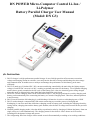
DN POWER Micro-Computer Control Li-Ion /
Li-Polymer
Battery Parallel Charger User Manual
(Model: DN G3)
¢ñ. Instruction
1. DN G3 charger is a high-performance parallel charger. It uses 24 high-precision AD converters to monitor
voltage and charging current in real-time, it not only has the function of charge and discharge but also storage
and communication. It enables users to analyze and manage the performance of their battery packs more
efficiently.
2. DN G3 is made up of 6 isolated DC / DC converters and being controlled by the main chip, the highest output
voltage of each DC/DC converts is 4.20V, resulting to optimal protection for the battery. Use of parallel charging
mode is hence greatly extended to the life cycle of the battery pack. Also, the electricity power being charged
using this mode is expected to be more than that being charged in series mode.
3. The EX-6 Cascade Charging Dock can be connected to DN G3. The charger performs its work by charging each
battery pack automatically once connecting the battery to Cascade Charging Dock. Therefore, manual operation
is not necessary.
4. DN G3 has the function of discharging, it could discharge 10 batteries in series at a discharging rate of 20W.
5. DN G3 works through a computerized USB contact connecting to record the process of charging and
discharging, it can store more than 1000 times charging record of battery pack, including the charging electricity,
setting current, charging time and the battery pack number; also the flux of voltage and current from the previous
charging.
6. With the parallel charging mode, it has the ability to perform its tasks by charging a Lithium-Ion battery from one
single cell up to 6 cells simultaneously. The charging status for the whole 6 cells is shown on LCD screen,
including their designated voltage and current.
7. The refrigerating fan of the charger will be turned on and off automatically according to its working conditions.
Charger has the functions of fan testing and automatic alarm of fan fault.
¢ò. Specifications & Operation Instructions
1. Input voltage: DC 11V~15V. Maximum working current is 4.0A when voltage is 12V. Operating temperature:
0~40 ¡æ
2. Charging current 0.5A~4.0A. Button on panel can be used to adjust charging current by 0.5 amp in progressive
degree.
3. There are 4 buttons on panel, namely - set, start/stop, function.
4. The LCD screen indicates the charging conditions for each cell in real-time. As being shown for charging
progress of each individual cell, once the individual cell is fully charged, a letter ¡°OK¡±is prompted on the
display for that cell. When charging of the whole pack is completed, buzzer will alarm.
Button on the lift side of panel can be used to adjust charging current between 0.5 A to 4 A by 0.5 amp in
progressive degree.
5. Insert 3 cells, LCD will show like this :
Set the number of charging battery pack, mainly use for analyzing a certain battery pack, then to scout and
analyze its capability. It can be set as PA0 to PA15,throughwhichthepackPA0 is especially set for charger
expanding EX-6, there is no record data in the charger. Press Start/Stop to start up charging after PA0 is set, then
a letter ¡°REC¡± appears that indicates the inserted batteries are being charged automatically and chronologically.
Press Start/Stop again to pause charging. There is no sound cue under the PA0 charging mode.
All PA1 to PA15 have the ability to record data while charging, and hence coordinating with computer software
providing efficiency for users in terms of analyzing the battery pack performance. It is suggested that users
should number their packs, including setting when charging.
PA value of the battery pack can be adjusted by pressing the left button (up/down). It will switch to charge
waiting should button is left non-press for a few seconds.
6. Charge
(1) In the course of charging, LCD screen indicates the voltage and charging current.
The picture shows above are a 3 cell-pack, which are being charged in channel 4,5,6 respectively, the flashing
light with letter reads ¡°Charging¡±indicating it is in the process of charging. The charging current will
progressively increase to the desired setting current once it is started, and it will also be adjusted by its program
works in accordance to the user¡¯s pre-set requirements.
The charger is likely fail to achieve its desired charging current as was set by user , e.g. input voltage that is too
high or too low; the charging battery voltage reaches 4.0V; above average high temperature; or resistance
between battery and charger cable etc.
(2) In the course of charging, press ¡°Function¡±to switch to the status of electricity display
It is the amp./h that has been charged into battery. Amp./h will be set up to 0 when the pack is being inserted, but
it will not be cleared out by pressing START/STOP button during the course of charging. Press FUNCTION
again brings back to the electricity display status.
(3) When it reaches 1/10 for the battery capacity or the minimum electric current is 0.2A,which means the battery
is fully-charged, proceeding with a ¡®beep¡¯ sound. The battery pack should be removed immediately otherwise
the charger will continue its charging work until all the electric current reaches 0Afollowed with a ¡®beep¡¯. It is
therefore, for safeguarding, users are advised to remove the battery once the charging job is completed.
(4) If EX-6 Cascade Charging Dock is also used, the charger will scan EX-6 and switch battery packs
automatically until all battery packs are fully charged, during which time there will be no buzz alarm. However
LED will indicate two statuses: charging and/or fully charged.
(5) When it is connected to the special charging transforming device - different accessories used may be tailored
to different Lithium-Ion battery packs, it is advisable to choose the correct output transferring port for the
designated battery pack.
7. Discharge
When uncharged, insert the battery in the discharge pole, (take notice of the polarity of the battery.) in 6-7
seconds the LCD will indicate below picture:
The picture shows the charger is in a discharging mode, the ending voltage and current of discharge could be set
by pressing the button; the data of discharging time, battery voltage and Ah will gradually show.
(1) ¡±¡ª¡°stands for time in ¡®minute¡¯, ¡°¡ª¡°flashingindicates it begins timing while discharging, the above
picture shows that the discharge has been completed for 60 minutes
(2) ¡±U1¡±stands for the battery voltage value that can be detected upon inserting the battery, it remains
unchanged during the course of discharge, the picture shows above as the voltage value is 12.0V.
(3) ¡±U2¡± stands for the present voltage, it will gradually reduce during the course of discharge, the picture
shows above is 8.9V.
(4) ¡±UA¡± stands for the desired voltage, the picture shows above is 7.2V, which could be set manually.
Discharging will be finished when U2 reaches UA and with a ¡®beep¡¯ sound.
(5) ¡±A¡± stands for discharging current, it could be adjusted manually, the picture above shows 1.5A.
(6) ¡±Ah¡± stands for the flux of discharging current in one-hour, the picture above shows 1.5Ah
(7) While discharging, user should first set the value of discharging current ¡°A¡± , and the desired voltage ¡°UA¡±, press ¡°function¡±, which will switch the setting status between current and desired voltage, through
¡°up/down¡± by setting the flux. And start discharging followed by pressing ¡°Start/Stop¡±
(8) The flux of setting current is affected by the power while discharging, the higher the voltage of that pack, the
lower the flux of the resulting current.
(9) G3 limits the lowest value of discharging voltage to a minimum of 75% from the present voltage value.
Therefore, it should not be lower than the minimum value while setting the desired voltage. There are several
factors taking into consideration while setting the desired voltage, such as numbers of the battery packs as well as
the minimum voltage rate of that specified battery pack. Users are therefore advised to take control the
discharging rate since this G3does not provide the over-discharge protection function.
8. Input power of charger is protected from reverse connection of polarity. So charger will not be damaged even if
input is connected adversely, hence the charger will stop working.
9. Charger has the function of safety protection which will not cause the pack to become over-charged and/or
damaged even the pack is left with full- charged. Nevertheless, it is suggested that the battery pack should be
removed immediately when charging job is completed
10. Check pole of battery carefully by using the right connecter and avoid connecting to the wrong pole. Should the
pack is accidentally connected to reverse polarity, no damage will cause to the charger and battery pack resulting
to a user-friendly safety protection function.
11. Use of the voltage should be 12V and the power should be over 150W. Should supply power is insufficient,
charging with low current is advisable. The optimal function of this charger will not be achieved if the voltage is
too high or low. When input voltage is higher than 18V, charger will become mal-function.
12. If input voltage is too low (i.e.<10. 5V) or too high (i.e. >14.5V), LCD screen will show a signal made with a
¡®battery pack¡¯ followed by a buzz alarm.
III. Performance function of communicated software
Connect the charger to computer through USB contact, using the applicable software connecting and controlling the
charger as well as downloading the previous charging record. All these could be done through analysis and comparison
of the capacity of the battery pack including single cell battery.
1. Through USB connection, previous charging records for individual pack¡¯s capacity, its relevant charging time
for cells as well as its charging progresses are shown.
2. The communication software reads the latest charging progress showing graphical curves for both the voltage
and current while charging.
3. If going on internet, the charger could be set and controlled by PC, e.g. the charging voltage, current, Ah, and
graphical curves of voltage and current are displayed in real time. (please refer to Software Instruction for
details).
IV. Note:
Requirement of power supply: +12VDC, power should be over 150W with overload protection. Notice should be taken
for the estimated voltage and the capacity in case of a lead battery. For multi-pack charging function, it is therefore
greatly advised that lead battery should not be used as the main power supply.
NOTE: Serial charging mode is forbidden.