1
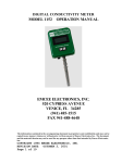
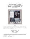
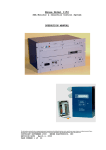
PRECISION CONDUCTIVITY METER
MODEL 1154
OPERATION MANUAL
EMCEE ELECTRONICS, INC.
520 Cypress Avenue
Venice, FL
34285
(941) 485-1515
FAX 941-488-4648
The information contained in the accompanying document is proprietary and confidential, and may not be copied in any manner
whatsoever without prior written consent of Emcee Electronics, Inc. The document and the material therein may not be used for any
purpose other than that intended by Emcee Electronics, Inc.
COPYRIGHT 2002 EMCEE ELECTRONICS, INC.
REVISION DATE: October 28, 2002
PRECISION CONDUCTIVITY METER
TABLE OF CONTENTS
PAGE NO.
1.0
Scope . . . . . . . . . . . . . . . . . . . . . .
3
2.0
Significance
. . . . . . . . . . . . . . . . . .
3
3.0
Definition
. . . . . . . . . . . . . . . . . . .
3
4.0
Summary of Method . . . . . . . . . . . . . . . .
4
5.0
Apparatus . . . . . . . . . . . . . . . . . . . .
4
Figures 1 - Model 1154 Conductivity
Meter with Fuel Cell . . . . . . . . . . .
5
6.0
Preparation of Sample . . . . . . . . . . . . . .
6
7.0
Cell Cleaning . . . . . . . . . . . . . . . . . .
6
8.0
Test Procedure
. . . . . . . . . . . . . . . . .
8
9.0
Report
. . . . . . . . . . . . . . . . . . . . .
9
Battery Replacement . . . . . . . . . . . . . . .
9
10.0
Service & Warranty Policy
See Emcee Electronics, Inc Service and Warranty Manual
The information contained in the accompanying document is proprietary and confidential, and may not be copied in any manner
whatsoever without prior written consent of Emcee Electronics, Inc. The document and the material therein may not be used for any
purpose other than that intended by Emcee Electronics, Inc.
COPYRIGHT 2002 EMCEE ELECTRONICS, INC.
REVISION DATE: October 28, 2002
Page 2 of 9
PRECISION CONDUCTIVITY METER
1.0
SCOPE
This method applies to the laboratory determination of the "rest"
electrical conductivity of aviation fuels and other similarly
low-conductivity liquids. Several instruments are available for
various ranges.
Model
Multiplier
154-00-0000
154-00-0002
X 1
X 10
Range
0 – 20,000 pS/m
0 – 200,000 pS/m
The instrument will display units between 0 and 19990. The
conductivity is equal to the reading, times the instrument
multiplier and is reported in picosiemens/meter (pS/m). The
2.0
SIGNIFICANCE
The generation and dissipation of electrical charge in fuel
depend largely on the ionic species present which may be
characterized by the "rest" electrical conductivity.
3.0
DEFINITION
3.1 "Rest" conductivity - the conductivity of uncharged fuel in
the absence of ionic depletion or polarization. It is, in
effect, the conductivity at the initial instant of a DC
measurement.
3.2 Picomho/meter - unit of electrical conductivity, also
often called a Conductivity Unit (CU). In the SI, picosiemens
replaces picomho.
1 ps/m = 1 x 10^-12 +/- ^-1 (m) ^-1
1 ps/m = 1 CU
1 ps/m = 1 picomho/m
The information contained in the accompanying document is proprietary and confidential, and may not be copied in any manner
whatsoever without prior written consent of Emcee Electronics, Inc. The document and the material therein may not be used for any
purpose other than that intended by Emcee Electronics, Inc.
COPYRIGHT 2002 EMCEE ELECTRONICS, INC.
REVISION DATE: October 28, 2002
Page 3 of 9
PRECISION CONDUCTIVITY METER
4.0
SUMMARY OF METHOD
A sample of fuel is placed in the conductivity cell which is
then connected in series with a DC voltage source and a
sensitive DC ammeter. The conductivity is calculated by Ohm's
law from the cell characteristics, the voltage across the cell,
and the almost instantaneous peak current reading.
5.0
APPARATUS
5.1
Components of apparatus A are shown in Fig. 1.
5.2 The conductivity cell, shown in Fig. 1 consists of an inner
electrode and an outer electrode separated with a teflon
insulator. The outer electrode and cap also provide a ground
path and electrostatic shield.
5.3 The measuring apparatus shown in Fig. 1 will supply the
fuel cell current and convert the output signal directly into
ps/m units. A pushbutton selector allows selection of zero,
calibrate, and 3 range selections.
5.4
Electrical connections, are completed by a triaxial cable.
5.5 The temperature probe is connected to the thermocouple
socket and is activated by pressing the “Temp” button as shown in
Fig.2.
The information contained in the accompanying document is proprietary and confidential, and may not be copied in any manner
whatsoever without prior written consent of Emcee Electronics, Inc. The document and the material therein may not be used for any
purpose other than that intended by Emcee Electronics, Inc.
COPYRIGHT 2002 EMCEE ELECTRONICS, INC.
REVISION DATE: October 28, 2002
Page 4 of 9
PRECISION CONDUCTIVITY METER
Figure 1
The information contained in the accompanying document is proprietary and confidential, and may not be copied in any manner
whatsoever without prior written consent of Emcee Electronics, Inc. The document and the material therein may not be used for any
purpose other than that intended by Emcee Electronics, Inc.
COPYRIGHT 2002 EMCEE ELECTRONICS, INC.
REVISION DATE: October 28, 2002
Page 5 of 9
PRECISION CONDUCTIVITY METER
6.0
6.1
PREPARATION OF SAMPLE
The sample volume should be at least 0.7L.
6.2 Use a clean, new epoxy-lined can, or a new glass bottle
that has been rinsed successively with hot water, distilled
water, acetone, and toluene-isopropyl alcohol mixture then
flushed with dry nitrogen. Use only non-contaminating caps.
6.3 Rinse the container several times with portions of the
fuel to be sampled. If possible fill the container, let stand,
then empty and refill. Avoid taking the sample for test by
pouring from the container; pipette instead. The sample should
be clean and bright when tested.
Note:
7.0
Bottle samples should be tested immediately,
since the glass surface tends to absorb from
the fuel the conductive substances that the
test is intended to measure.
CELL CLEANING
7.1 The cleaning procedure to be used for the cell depends
largely on the nature of the sample to be measured. For
samples above 20 ps/m rinsing with a toluene-isopropyl alcohol
mixture and air drying is normally sufficient. Below 20 ps/m
one of the following is recommended:
7.1.1 If the sample to be measured is a fuel with a similar
conductivity to that measured in the previous test, the cell
need only be rinsed a few times with treated n-heptane (Ref.
7.4).
7.1.2 If the sample to be measured differs in conductivity from
that measured in the previous test, or has a much lower
conductivity, the cell should be rinsed thoroughly for five times
with fresh toluene-isopropyl alcohol mixture, followed by rinsing
with treated n-heptane.
7.2 After cleaning, check the cleanliness of the cell by
measuring the conductivity of the treated n-heptane. This
should be lower than 0.03 ps/m.
The information contained in the accompanying document is proprietary and confidential, and may not be copied in any manner
whatsoever without prior written consent of Emcee Electronics, Inc. The document and the material therein may not be used for any
purpose other than that intended by Emcee Electronics, Inc.
COPYRIGHT 2002 EMCEE ELECTRONICS, INC.
REVISION DATE: October 28, 2002
Page 6 of 9
PRECISION CONDUCTIVITY METER
7.3 If the conductivity of the treated n-heptane is found
to be higher than 0.03 ps/m, repeat the cleaning and checking
procedures.
7.4
Preparation of n-heptane
7.4.1 Prepare by percolating ASTM reference fuel grade
n-heptane through silica gel as follows:
7.4.2 Activate approximately 2000 g of 100 to 200 mesh silica
gel by heating at 180 degrees C for 24 hrs. Allow it to cool in
a desiccator under nitrogen or in vacuum. Soak approximately
0.5 g of glass wool for 24 hrs. in clean n-heptane.
7.4.3 Take a tube of borosilicate glass having an inside
diameter of 60 to 70 mm, a length 1500 mm, with a conically
shaped lower end provided with a glass cock. Place a perforated
porcelain disk (diameter 25 mm) in the lower end of the tube and
put the soaked glass wool on top of the disk. Fill the tube with
the activated silica gel while tapping to achieve homogeneous
filling. The silica gel layer will be approximately 1250 mm
high. Wrap the column in black paper to execute light.
7.4.4 Percolate n-heptane through the column at a rate of about
2 to 3 liter/hr. Discard the first 3 liters. Never allow the
column to run dry. The silica gel charge is sufficient for the
percolation of 1000 liters of n-heptane, provided the
conductivity of the untreated n-heptane is below 1 ps/m.
Note:
If the conductivity of the n-heptane after
treatment is higher than 0.03 ps/m the
treatment should be repeated.
The information contained in the accompanying document is proprietary and confidential, and may not be copied in any manner
whatsoever without prior written consent of Emcee Electronics, Inc. The document and the material therein may not be used for any
purpose other than that intended by Emcee Electronics, Inc.
COPYRIGHT 2002 EMCEE ELECTRONICS, INC.
REVISION DATE: October 28, 2002
Page 7 of 9
PRECISION CONDUCTIVITY METER
8.0
TEST PROCEDURE
8.1
Remove cell and cable from meter.
8.2
Set the AUTO/MANUAL switch to MANUAL.
8.3 Depress the 20 switch, digital reading should indicate
0.00 +/- .02 ps/m after 3 seconds.
8.4 Depress the CAL switch, digital reading should indicate
1000 +/- 3.
8.5 If low battery indicator is displayed during measure or
calibration, the internal batteries should be replaced.
8.6
Attach the cleaned cell to the CU meter as shown in Fig. 1.
8.7
0.0
Depress the ZERO switch, digital reading should indicate
+/- .02 CU.
8.8 Depress the CAL switch, digital reading should indicate
1000 +/- 5 CU.
8.9
Set the AUTO/MANUAL switch to AUTO.
8.10 Flush the cleaned cell three times with the sample, empty
the cell completely, then fill the outer chamber until sample
flows into center receptacle. (Allow the center receptacle to
fill approximately 1 inch for temperature measurement.)
8.11 Allow some time for electric charges, generated by handling
the equipment, to flow away, if it is expected that the sample
has a conductivity below 1 ps/m.
8.12 If the sample conductivity is known select the
corresponding range position. When conductivity is unknown,
first check the fuel on the 2000 ps/m range position then
read on lower scale if appropriate.
8.13 Depress appropriate MEASURE SWITCH and record ps/m value
(correct reading is highest value observed after 3 second delay).
In AUTO mode, reading is stabilized after 3 seconds and held on
display for 9 seconds. In the MANUAL mode, bias voltage is
maintained and the current is continuous as long as the switch
is held.
The information contained in the accompanying document is proprietary and confidential, and may not be copied in any manner
whatsoever without prior written consent of Emcee Electronics, Inc. The document and the material therein may not be used for any
purpose other than that intended by Emcee Electronics, Inc.
COPYRIGHT 2002 EMCEE ELECTRONICS, INC.
REVISION DATE: October 28, 2002
Page 8 of 9
PRECISION CONDUCTIVITY METER
8.14
Repeat readings may be taken after 1 minute delay.
8.15 Insert the probe in the center receptacle and read the
sample temperature by depressing the TEMP switch.
9.0
REPORT
9.1 Conductivity of the sample in ps/m as the average of the
last two determinations.
9.2
10.0
Temperature at time of conductivity measurement.
BATTERY REPLACEMENT
When batteries become weak a LOW BAT indication is made on the
display during test. On this occurrence remove the four bottom
screws and replace all 6 standard 9 volt cells.
The information contained in the accompanying document is proprietary and confidential, and may not be copied in any manner
whatsoever without prior written consent of Emcee Electronics, Inc. The document and the material therein may not be used for any
purpose other than that intended by Emcee Electronics, Inc.
COPYRIGHT 2002 EMCEE ELECTRONICS, INC.
REVISION DATE: October 28, 2002
Page 9 of 9