1
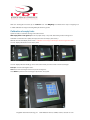
Installation & Calibration
SkidFleet System for Tamsa Material Handling
Vehicles
Integrated Visual Data Technology Inc. 3439 Whilabout Terrace, Oakville, Ontario, Canada L6L 0A7
Installation & Calibration for Tamsa SkidFleet System
This SkidFleet system installation & calibration guide describes how to install, calibrate, test and use your on-board
check weighing & utilization with downtime reasons with overload function. Following the instructions in this guide will
enable you to get your system operating quickly and easily. In the event that you require additional assistance, please
contact customer support via e-mail at [email protected] or visit www.skidweight.com
or contact us at the
address or contact number below:
Integrated Visual Data Technology Inc.
3439 Whilabout Terrace, Oakville, ON, Canada, L6L 0A7
Phone: 905-469-0985, Fax: 905-825-9494
On-board Load Weighing, Overload Warning and Vehicle Usage
Safety
Always disconnect the vehicle battery while installing SkidFleet system or any other electronic product. Make sure sure
that unit, pressure transducer and any other associated cables are securely mounted and do not impede any of the
vehicle’s controls. Use care when routing the components cables. Route the cables where they will be protected. Use
commonly accepted install practices for after market industrial vehicle electronic devices. The installation of the SkidFleet
systems should only be performed by an acknowledged lift truck dealer technician or end user electro and hydraulic
technical installer.
Here are two acceptable methods of making a wire connections:
* Soldering your connections (recommended)
* Crimp connectors (with the use of the proper crimping tool)
Regardless of the method you choose, ensure that the connection is mechanically sound and properly insulated. Use
high quality electrical tape and shrink tubing where necessary.
This product is connected directly to the vehicle’s ignition switch, 12 to 55 V DC. There is no on-off switch on the unit.
Integrated Visual Data Technology Inc. 3439 Whilabout Terrace, Oakville, Ontario, Canada L6L 0A7
Electro-Magnetic Compatibility
CE conformity to EC directive 89/336 (EMC) by application of harmonized standards: Interference stability EN 61000-6-2
and EN 61326-1 interference emit EN 61000-6-3, EN 61326-1 for the pressure transducer.
SkidFleet Series
Our policy is one of continuous improvement and the information in this document is subject to change without notice.
Check that software version displayed on LCD is the one applicable for your application.
Overview of components
The standard SkidFleet system consist of two main components:
* Digital indicator with wiring harness, mounting bracket
* Hydraulic pressure transducer with 3 wires cable
* Installation & calibration manual and operator usage instruction
Operational principal
The SkidFleet system check weighing operational principal is based on the hydraulic pressure transducer mounted in
the vehicle lifting hydraulic circuit that will automatically activate the “weighing cycle / specific algorithm ” every time a
skid load is lifted just above the ground. The increase in pressure is converted in an electronic signal at the sample rate of
16000 readings which is converted into a load weight reading. The SkidFleet models equipped with the impact detection
system have the impact module mounted inside the SkidFleet enclosure.
Note: Standard SkidFleet units without impact detection module can be installed on lift truck regardless of the mounting
angle or location. SkidFleet units equipped with optional impact detection module must be installed on the lift truck
in in such a way that LCD display is facing forward direction of vehicle travel, indicator mounted in vertical position having
up to +/- 15 degree angle that is allowed for proper operation.
Pressure transducer installation
The pressure transducer must be installed in the lifting hydraulic line between the lift control valve and lift
cylinder(s). Mount a T-piece in lifting hydraulic line. In some cases you can install the pressure transducer in the flow
divider, drilling and tapping for 1/4”-18 NPT male in spare plug (if only single or double mast configuration) or in the body
of the flow divider. Also, you can drill and tap on any “larger elbow” that might be available in the hydraulic lifting circuit
!
found in vehicles with larger hoses to accommodate larger vehicle lifting capacities
!
!
.
!
Integrated Visual Data Technology Inc. 3439 Whilabout Terrace, Oakville, Ontario, Canada L6L 0A7
Pressure transducer installation precautions
Before installation of the pressure transducer the hydraulic lift circuit must be pressure free.
There are two ways to do that:
1. Place the forks on the ground in their lowest position and make the hydraulic system pressure free by tilting the mast
forward. The chain(s) should be slack.
2. Lift the forks and position them on the top of a supporting fixture. Start lowering the lifting cylinder into its lowest
position. Be sure that chain(s) are slack.
Make sure that that installed pressure transducer will not touch any moving parts or assembly of the vehicle while in
normal operation. Pressure transducer has 1/4”-18 NPT male thread. Use thread seal to ensure tight fit.
!
Selecting the mounting location for digital indicator
Use the mounting bracket to fasten digital indicator on the vehicle dashboard, side railing or preferably on the top of the
operator guard enclosure, right hand side.
!
There are many examples of mounting locations that will depend on the vehicle model. However, additional mounting
items such as a flat brackets may be needed to help secure the unit to upper right corner of the guard or side railing.
Compact size
All of the SkidWeigh systems are compact size, housing dimension of only 178 mm x 127 mm x 43 mm.
Electrical Connections
All of the SkidFleet systems operate from 12 to 55 V DC.
Note: The main cable for pressure transducer and power supply are the same colour code for all SkidFleet versions.
Digital indicator with five wires single cable.
- Orange Wire (+) Ignition switch “on position”
- Brown Wire (-) Battery negative
- Red Wire, connect to RED wire of the pressure transducer cable
Integrated Visual Data Technology Inc. 3439 Whilabout Terrace, Oakville, Ontario, Canada L6L 0A7
- Black Wire, connect to BLACK wire of the pressure transducer cable
- White Wire, connect to WHITE wire of the pressure transducer cable
Pressure transducer cable (Cable with 3 wires: red,white and black)
Electrical power short circuit protection
- All of the SkidFleet systems are internally short circuit protected with resettable fuse. There is no need to install external
inline fuse in orange wire connected to the ignition switch, vehicle positive connection 12 to 55 V DC.
- Automotive 60 V load dump protection. Reversal power supply protection.
“Quick test to determine if electrical connections are done right”
After you have connected electrical power and pressure transducer cable you can check the system operation.
- Tap on Home input and tap on the “Clock & More” icon on LCD display.
If the above test is valid than the
system and pressure transducer electrical connections are done right.
The next procedure will be to calibrate the SkidFleet weighing function
-Lift truck equipped with hydraulic accumulator
If the standard SkidFleet system is installed on the lift trucks equipped with hydraulic accumulators, please contact us
to provide you with input instruction to enter specific software algorithm to obtain load weight accuracy within +/- 0.1
!
to 1% of vehicle maximum lifting capacity.
Hydraulic accumulator installed with lifting cylinder
Integrated Visual Data Technology Inc. 3439 Whilabout Terrace, Oakville, Ontario, Canada L6L 0A7
Weighing function calibration procedure
The SkidFleet calibration is automatic and is done by lifting empty and loaded forks (or any other attachment such as
paper clamp) just above the ground. MAKE SURE THAT YOU HAVE A KNOWN LOAD WEIGHT AND KEEP IT
NEARBY TO COMPLETE THE CALIBRATION.
For the best results use at least minimum calibration load test weight of 30 to 50% of maximum lifting capacity of the lift
truck. Use customer floor scale or find a known skid load weight within the operational facility.
Important: If you want the system to show load weight in pounds, use the known load weight in pounds and
enter that value accordingly. The same would apply if you want the system to show load weight in kilograms.
System Set Up & Calibration
- Tap on the icon showing Clock & More.
Date / Time Set Up
- Tap on the icon “Set Clock”.
!
!
!
!
!
!
- Use “Set” and “arrow up” and “arrow down” input to change time and date if required
- When done tap on “Home” icon to save the values.
Integrated Visual Data Technology Inc. 3439 Whilabout Terrace, Oakville, Ontario, Canada L6L 0A7
Vehicle ID#
- Tap on the icon “Admin”.
- Password table will be shown.
- Enter a following password: A123 and press “enter key”.
- Enter valid Vehicle ID#
Note: Maximum 4 digits !
- Tap on “Enter key” to confirm the vehicle ID#.
!
!
!
!
!
!
!
!
SkidFleet weighing function calibration starting point
Lower the empty forks to the ground.
There should be no hydraulic pressure in lift hydraulic circuit.
Turn ignition switch to on position (electric lift trucks) and start the engine on combustion powered lift trucks.
LCD display will show standard weighing mode.
Tap on “Home” icon.
!
!
!
!
Integrated Visual Data Technology Inc. 3439 Whilabout Terrace, Oakville, Ontario, Canada L6L 0A7
With LCD showing all of the icons, tap on “Calibrate” icon. The “Weighing” icon will be shown. Tap on “weighing” icon
to initiate calibration of empty forks being lifted just above the ground.
Calibration of empty forks
System is ready for automatic zeroing of the scale function.
With empty forks on the ground, lift forks or (Paper clamp or any other attachment) just above the ground.
Activate lift control valve and “quickly” lift empty forks. Do not lift empty forks slowly !
Wait few seconds until display shows 100%. Calibration of the empty forks lifted just above the ground is done.
The LCD display will indicate to lower empty forks.
The LCD display will automatically go to the next screen where you have to enter a known load weight.
Example: “Known load weight is 4000”.
Note: The known load weight could be in pounds or kilograms.
Press Enter key when known load weight is inputed into the system.
Integrated Visual Data Technology Inc. 3439 Whilabout Terrace, Oakville, Ontario, Canada L6L 0A7
Calibration of loaded forks with known load weight lifted above the ground
With loaded forks on the ground, lift forks or (Paper clamp or any other attachment) just above the ground.
- Activate lift control valve and “quickly” lift loaded forks. Do not lift forks slowly !
- Wait few seconds until display shows 100%.
- The LCD display will indicate to lower empty forks.
!
!
!
!
!
!
!
!
!
!
!
!
!
Calibration of the weighing function for SkidFleet system is done
!
!
Integrated Visual Data Technology Inc. 3439 Whilabout Terrace, Oakville, Ontario, Canada L6L 0A7
Lift Truck Overload Warning Input
SkidFleet systems with optional overload warning function will have LCD screen advanced automatically to “Enter
Overload Value” table after the calibration of the weighing function with known load weight is finished.
At that point enter the overload warning value that is applicable for your vehicle application.
Press Enter key to confirm entered overload value.
Example shown: 4500.
NOTE: Overload condition will activate audio warning.
- LCD display will also show overload warning indicating the overload value and it will “flash”.
- To stop the overload audio / visual warning you must lower the load to the ground.
- Every overload event will be recorded and reported.
!
Integrated Visual Data Technology Inc. 3439 Whilabout Terrace, Oakville, Ontario, Canada L6L 0A7
TAMSA
Lift Truck Utilization & Downtime Reasons with USB Memory Stick Recording
Integrated Visual Data Technology Inc. 3439 Whilabout Terrace, Oakville, Ontario, Canada L6L 0A7
User’s Manual
- Insert the forks into the load, lower the
forks to the ground.
- LCD will show “Load Weight Total”
Load weighing starting point
!
- Lift the load weight just above the
ground
- Do not lift the load “slowly” or to
different forks load heights
Proper weighing procedure
- LCD will show “Please Wait” with % of
the weighing cycle status
!
- After few seconds LCD will show
“Done” with lifted load weight value
- The SkidFleet with optional onboard
printer connected if you tap on “Send”
Individual load weight
input you will get a printout ticket or
record on USB or to the base station
!
- To initiate another load weight
procedure repeat above procedure
!
Integrated Visual Data Technology Inc. 3439 Whilabout Terrace, Oakville, Ontario, Canada L6L 0A7
- SkidFleet with optional Waybill ID#
function, if you tap on “Send” input
the LCD screen input for Waybill No:
will prompt you to enter a valid Waybill
number.
Optional Waybill ID# input
- Press Enter key
for load weights
!
- SkidFleet with optional accumulative
load weight total, tap on “Add” input to
keep totalizing the load weights.
!
Optional accumulative load
weight total
!
Integrated Visual Data Technology Inc. 3439 Whilabout Terrace, Oakville, Ontario, Canada L6L 0A7