1
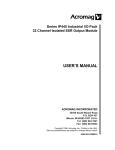
CJ1W-OC/OA/OD
CN1
Jxx_Ch1_Out02
L
L
L
L
L
Jxx_Ch1_Out03
Jxx_Ch1_Out04
Jxx_Ch1_Out05
Jxx_Ch1_Out06
Jxx_Ch1_Out07
0V
COM0 (+V)
L
L
Wd m+1
External connection
and terminal-device
variable diagram
L
L
L
L
L
L
Jxx_Ch2_Out00
Jxx_Ch2_Out01
Jxx_Ch2_Out02
Jxx_Ch2_Out03
Jxx_Ch2_Out04
Jxx_Ch2_Out05
Jxx_Ch2_Out06
Jxx_Ch2_Out07
0V
COM1 (+V)
38 37
36 35
34 33
32 31
30 29
28 27
26 25
24 23
22 21
20 19
18 17
16 15
14 13
12 11
10 9
8 7
6 5
4 3
2 1
L
Jxx_Ch1_Out09
L
Jxx_Ch1_Out10
L
Jxx_Ch1_Out11
Jxx_Ch1_Out12
Jxx_Ch1_Out13
Jxx_Ch1_Out14
Jxx_Ch1_Out15
L
L
COM3 (+V)
0V
L
L
L
0V
COM0 (+V)
Jxx_Ch2_Out08
Jxx_Ch2_Out09
Jxx_Ch2_Out10
Jxx_Ch2_Out11
Jxx_Ch2_Out12
Jxx_Ch2_Out13
Jxx_Ch2_Out14
Jxx_Ch2_Out15
L
Jxx_Ch4_Out15
L
Jxx_Ch4_Out14
L
Jxx_Ch4_Out13
L
Jxx_Ch4_Out12
L
Jxx_Ch4_Out11
L
Jxx_Ch4_Out10
L
Jxx_Ch4_Out09
L
Jxx_Ch4_Out08
COM2 (+V)
L
0V
L
L
L
L
Allocated
CIO word
L
L
L
0V
COM1 (+V)
12 to
24 VDC
• When wiring, pay careful attention to the polarity of the external
power supply. The load may operate incorrectly if the polarity is
reversed.
• Be sure to wire both terminals 21 and 22 (COM0 (+V)) of CN1.
• Be sure to wire both terminals 1 and 2 (COM1 (+V)) of CN1.
• Be sure to wire both terminals 23 and 24 (0 V) of CN1.
• Be sure to wire both terminals 3 and 4 (0 V) of CN1.
• The signal names of the terminals are the device variable
names.The device variable names are the names that use "Jxx" as
the device name.
L
Jxx_Ch3_Out15
L
Jxx_Ch3_Out14
L
Jxx_Ch3_Out13
L
Jxx_Ch3_Out12
L
Jxx_Ch3_Out11
L
Jxx_Ch3_Out10
L
Jxx_Ch3_Out09
L
Jxx_Ch3_Out08
1 2
3 4
5 6
7 8
9 10
10 12
13 14
15 16
17 18
19 20
21 22
23 24
25 26
27 28
29 30
31 32
33 34
35 36
37 38
39 40
COM3 (+V)
0V
Jxx_Ch4_Out07
L
Jxx_Ch4_Out06
L
Jxx_Ch4_Out05
L
Jxx_Ch4_Out04
L
Jxx_Ch4_Out03
L
Jxx_Ch4_Out02
L
Jxx_Ch4_Out01
L
Jxx_Ch4_Out00
L
Wd m+3
L
40 39
Signal
name
COM2 (+V)
0V
Jxx_Ch3_Out07
L
Jxx_Ch3_Out06
L
Jxx_Ch3_Out05
L
Jxx_Ch3_Out04
L
Jxx_Ch3_Out03
L
Jxx_Ch3_Out02
L
Jxx_Ch3_Out01
L
Jxx_Ch3_Out00
L
Wd m+2
Jxx_Ch1_Out01
Connector
pin
12 to
24 VDC
12 to
24 VDC
Wd m+3
L
Jxx_Ch1_Out08
Signal
name
Allocated
CIO word
Wd m+2
L
Jxx_Ch1_Out00
Allocated
CIO word
Signal
name
Wd m
Connector pin
Signal
name
Wd m+1
Wd m
Allocated
CIO word
CN2
12 to
24 VDC
• When wiring, pay careful attention to the polarity of the external
power supply. The load may operate incorrectly if the polarity is
reversed.
• Be sure to wire both terminals 21 and 22 (COM2 (+V)) of CN2.
• Be sure to wire both terminals 1 and 2 (COM3 (+V)) of CN2.
• Be sure to wire both terminals 23 and 24 (0 V) of CN2.
• Be sure to wire both terminals 3 and 4 (0 V) of CN2.
• The signal names of the terminals are the device variable
names.The device variable names are the names that use "Jxx" as
the device name.
26