1
Table of Contents
Index
Feature Supplement Manual
YP2425F-2470, YP4025F-1630 and YP4025F-1670
YP2425F and YP4025F Dry Fertilizer/Seeder
Manufacturing, Inc.
www.greatplainsmfg.com
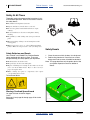
Read the operator manual entirely. When you see this symbol, the
subsequent instructions and warnings are serious - follow without
exception. Your life and the lives of others depend on it!
31088
Illustrations may show optional equipment not supplied with standard unit or may
depict similar models where a topic is identical.
EN
ORIGINAL INSTRUCTIONS
© Copyright 2013
Printed 2013-03-25
Table of Contents
Index
403-362M
Table of Contents
Index
Table of Contents
Index
Great Plains Manufacturing, Inc.
Cover
Index
iii
Table of Contents
Important Safety Information ......................................1
Safety Decals .................................................................4
Introduction ..................................................................6
Description of Unit ..........................................................6
Intended Usage ..........................................................6
Models Covered .............................................................6
Document Family........................................................7
Using This Manual..........................................................7
Definitions...................................................................7
Preparation and Setup .................................................8
Initial Setup.....................................................................8
Post-Delivery/Seasonal Setup........................................8
Hitching and Leveling .....................................................8
Operating Instructions.................................................9
Pre-Start Checklist .........................................................9
Planter Folding and Raising ...........................................9
Transport ......................................................................10
Typical YP2425F Weights ........................................10
Typical YP4025F Weights ........................................10
Loading Materials .........................................................11
Loading Seed ...........................................................11
Loading Fertilizer ......................................................12
Changing Seed Box or Hopper ....................................13
Air Systems Operation .................................................14
Seeding System Overview .......................................15
Fertilizer System Overview.......................................17
Fan Circuit Operation ...........................................18
Fan General Operating Information......................19
Butterfly Valves.....................................................19
Butterfly Valve Operation:.....................................19
Symptoms of Insufficient Air Flow ........................19
Symptoms of Excessive Air Flow .........................19
Monitor Operation.........................................................20
Marker Operation .........................................................20
Field Set-Up Checklists ................................................21
Field Operation.............................................................21
Short-Term Parking ......................................................21
Long-Term Storage ......................................................21
Adjustments................................................................22
Setting Material Rates ..................................................23
Setting Seed Rate ....................................................23
Setting Dry Fertilizer Rate ........................................23
Seed Meter Final Drive Range .................................23
Setting Variable Rate Gearbox ................................ 24
Meter Calibration...................................................... 25
Revolutions for Sample Size ................................ 25
Calibration Procedure .......................................... 25
Initial Calibration Steps ........................................ 25
Row Sample Calibration....................................... 26
Meter Sample Calibration..................................... 27
Calibration Adjustment ............................................. 28
Calibration: Rate Calculation................................ 28
Calibration: Gearbox Adjustment ......................... 28
Coulter Adjustment ...................................................... 29
Coulter Height Adjustment ....................................... 29
Coulter Applicator Adjustment.................................. 29
Frame-Mounted Coulter Force................................. 30
Troubleshooting......................................................... 31
Maintenance ............................................................... 34
Maintenance ................................................................ 34
No-Change Maintenance Items ................................... 34
Material Clean-Out....................................................... 35
Seeding System Clean-Out...................................... 35
Fertilizer System Clean-Out ..................................... 35
Meter Flute Replacement......................................... 36
Problem Fertilizer Clean-Outs.................................. 36
Removing Meter Box............................................ 37
Hopper Entry ............................................................ 37
Chain Maintenance ...................................................... 39
Fertilizer Meter Drive Chain ..................................... 39
Maintenance Schedule ................................................ 40
Seed Lubricants ....................................................... 45
Options ....................................................................... 46
Compatible Options ..................................................... 46
Options Not Recommended......................................... 46
Incompatible Options ................................................... 46
Appendix A - Reference Information........................ 47
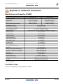
Specifications and Capacities YP4025F ...................... 47
Tire Inflation Chart ....................................................... 47
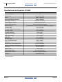
Specifications and Capacities YP2425F ...................... 48
Torque Values Chart.................................................... 49
Hydraulic Diagrams...................................................... 49
Chain Routing YP2425F .............................................. 50
Chain Routing YP4025F .............................................. 51
Appendix B - Monitor Setup...................................... 53
Seed Monitor Console Setup ....................................... 53
Pre-Programming Preparation: ................................ 53
© Copyright 2012, 2013 All rights Reserved
Great Plains Manufacturing, Inc. provides this publication “as is” without warranty of any kind, either expressed or implied. While every precaution has been
taken in the preparation of this manual, Great Plains Manufacturing, Inc. assumes no responsibility for errors or omissions. Neither is any liability assumed for
damages resulting from the use of the information contained herein. Great Plains Manufacturing, Inc. reserves the right to revise and improve its products as
it sees fit. This publication describes the state of this product at the time of its publication, and may not reflect the product in the future.
Trademarks of Great Plains Manufacturing, Inc. include: Singulator Plus, Swath Command, Terra-Tine.
Registered Trademarks of Great Plains Manufacturing, Inc. include:
Air-Pro, Clear-Shot, Discovator, Great Plains, Land Pride, MeterCone, Nutri-Pro, Seed-Lok, Solid Stand,
Terra-Guard, Turbo-Chisel, Turbo-Chopper, Turbo Max, Turbo-Till, Ultra-Till, Verti-Till, Whirlfilter, Yield-Pro.
Brand and Product Names that appear and are owned by others are trademarks of their respective owners.
Printed in the United States of America
2013-03-25
Cover
Index
403-362M
iv
YP2425F/YP4025F
Table of Contents
Change User Level to Dealer Level ......................... 53
Auto Configuration ................................................... 54
To Run Auto Config:............................................. 54
Row Status/Row Width Setup .................................. 54
Material Configuration Setup
(Controlled Hydraulic Drive) ............................. 55
Planter Control Channel Setup ................................ 56
Valve Calibration ...................................................... 57
Row Monitor Setup .................................................. 57
Speed Set Calibration Setup.................................... 58
Accessory Sensor Setup.......................................... 59
Hopper Assignment.............................................. 59
RPM Assignment ................................................. 59
403-362M
Index
Great Plains Manufacturing, Inc.
Clutch Folding Module (CFM) Setup ........................60
Clutch Folding Module Operation .............................60
5 Revolution Test......................................................60
Summary Screen ......................................................61
Appendix C - Fertilizer Rate Charts ..........................62
Reading the Fertilizer Rate Chart .................................62
Fertilizer Rates .............................................................63
Fertilizer Rates, 70cm Row Spacing.........................64
Fertilizer Rates, 30 inch Row Spacing......................65
Density Adjustment.......................................................66
Index ............................................................................67
Table of Contents
Index
2013-03-25
Great Plains Manufacturing, Inc.
Table of Contents
Index
1
Index
403-362M
Important Safety Information
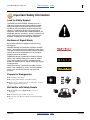
Look for Safety Symbol
The SAFETY ALERT SYMBOL indicates there is a
potential hazard to personal safety involved and extra
safety precaution must be taken. When you see this
symbol, be alert and carefully read the message that
follows it. In addition to design and configuration of
equipment, hazard control and accident prevention are
dependent upon the awareness, concern, prudence and
proper training of personnel involved in the operation,
transport, maintenance and storage of equipment.
Be Aware of Signal Words
Signal words designate a degree or level of hazard
seriousness.
DANGER indicates an imminently hazardous situation
which, if not avoided, will result in death or serious injury.
This signal word is limited to the most extreme situations,
typically for machine components that, for functional
purposes, cannot be guarded.
WARNING indicates a potentially hazardous situation
which, if not avoided, could result in death or serious
injury, and includes hazards that are exposed when
guards are removed. It may also be used to alert against
unsafe practices.
CAUTION indicates a potentially hazardous situation
which, if not avoided, may result in minor or moderate
injury. It may also be used to alert against unsafe
practices.
Prepare for Emergencies
▲ Be prepared if a fire starts.
▲ Keep a first aid kit and fire extinguisher handy.
▲ Keep emergency numbers for doctor, ambulance, hospital
and fire department near phone.
Be Familiar with Safety Decals
▲ Read and understand “Safety Decals” on page 4,
thoroughly.
▲ Read all instructions noted on the decals.
▲ Keep decals clean. Replace damaged, faded and illegible
decals.
2013-03-25
Table of Contents
2
YP2425F/YP4025F
Table of Contents
Index
Great Plains Manufacturing, Inc.
Index
2013-03-25
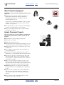
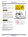
Wear Protective Equipment
Great Plains advises use of the following personal safety
equipment.
▲ Hearing protection, such as earmuffs or earplugs, for
making planter adjustments with the hydraulic fan
running.Prolonged exposure to loud noise can cause
hearing impairment or loss.
Avoid wearing entertainment headphones while operating
machinery. Operating equipment safely requires the full
attention of the operator.
▲ Face shield, goggles or full face respirator when handling
treated seed, seed lubricants or seed treatment.
▲ Gloves for working near sharp objects, and for handing
lubricants or treatments.
Handle Chemicals Properly
Agricultural chemicals can be dangerous. Improper use
can seriously injure persons, animals, plants, soil and
property.
▲ Read and follow chemical supplier instructions.
▲ Wear protective clothing.
▲ Handle all chemicals with care.
▲ Agricultural chemicals can be dangerous. Improper use can
seriously injure persons, animals, plants, soil and property.
▲ Inhaling smoke from any type of chemical fire is a serious
health hazard.
▲ Store or dispose of unused chemicals as specified by the
chemical manufacturer.
▲ If chemical is swallowed, carefully follow the chemical
manufacturer’s recommendations and consult with a doctor.
▲ If persons are exposed to a chemical in a way that could
affect their health, consult a doctor immediately with the
chemical label or container in hand. Any delay could cause
serious illness or death.
▲ Dispose of empty chemical containers properly. By law
rinsing of the used chemical container must be repeated
three times. Puncture the container to prevent future use. An
alternative is to jet-rinse or pressure rinse the container.
▲ Wash hands and face before eating after working with
chemicals. Shower as soon as application is completed for
the day.
▲ Apply only with acceptable wind conditions. Wind speed
must be below 8 kph (5 mph). Make sure wind drift of
chemicals will not affect any surrounding land, people or
animals.
▲ Never wash out a hopper within 30m (100 feet) of any
freshwater source or in a car wash.
403-362M
Table of Contents
Great Plains Manufacturing, Inc.
Table of Contents
Index
Important Safety Information
3
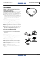
Confined Space
With materials loaded, or once used for hazardous
fertilizers, or seeds with hazardous treatments, your
fertilizer hopper may become a
“permit-required confined space”
under applicable statutes, regulations, insurance rules or
business policy. The vent tube structure in the hopper
has features to assist escape, and is not for routine entry.
▲ A hopper that is full or merely appears full can be an
entrapment hazard. You can sink entirely into the material,
or into an oxygen-deficient void, and suffocate in a matter of
seconds. Fertilizer bridges and crusts are especially
dangerous.
▲ When hazardous fumes are present, you can be quickly
overcome even with the hopper lid open.
▲ Do not enter a hopper for material loading, material
unloading, hopper cleaning or meter maintenance.
▲ Clean hopper by power washing from outside hopper top.
▲ Perform meter maintenance by removing meter from bottom
of empty hopper.
▲ If obstruction removal or repair requires hopper entry, have
the work performed by a team trained in confined space
procedures. See “Hopper Entry” on page 37.
Practice Safe Maintenance
▲ Understand procedure before doing work. Use proper
tools and equipment. Refer to this manual for additional
information.
▲ Work in a clean, dry area.
▲ Lower the planter, put tractor in park, turn off engine, and
remove key before performing maintenance.
▲ Make sure all moving parts have stopped and all system
pressure is relieved.
▲ Allow planter to cool completely.
▲ Disconnect battery ground cable (-) before servicing or
adjusting electrical systems or before welding on planter.
▲ Inspect all parts. Make sure parts are in good condition
and installed properly.
▲ Remove buildup of grease, oil or debris.
▲ Remove all tools and unused parts from planter before
operation.
2013-03-25
Table of Contents
Index
403-362M
4
YP2425F/YP4025F
Table of Contents
Index
Great Plains Manufacturing, Inc.
Safety At All Times
Thoroughly read and understand the instructions in this
manual before operation. Read all instructions noted on
the safety decals.
▲ Be familiar with all planter functions.
▲ Operate machinery from the driver’s seat only.
▲ Do not leave planter unattended with tractor engine
running.
▲ Do not stand between the tractor and planter during
hitching.
▲ Keep hands, feet and clothing away from power-driven
parts.
▲ Wear snug-fitting clothing to avoid entanglement with
moving parts.
▲ Watch out for wires, trees, etc., when folding and raising
planter. Make sure all persons are clear of working area.
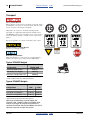
Safety Decals
Safety Reflectors and Decals
Your YP2425F and YP4025F Dry Fertilizer/Seeder
comes equipped with decals in place. They were
designed to help you safely operate your implement.
▲ Read and follow decal directions.
▲ Keep all safety decals clean and legible.
▲ Replace all damaged or missing decals. Order new decals
from your Great Plains dealer. Refer to this section for
proper decal placement.
1. Clean the area on which the decal is to be placed.
2. Peel backing from decal. Press firmly on surface,
being careful not to cause air bubbles under decal.
Note: This page describes only the option decals. See
your planter Operator manual for additional
decals.
▲ When ordering new parts or components, also request
corresponding safety decals.
To install new decals:
848-519C
Warning: Confined Space Hazard
On upper left facet of fertilizer hopper;
1 total
See page 12 and page 35 through page 37 for further
information.
403-362M
Table of Contents
31165
Index
2013-03-25
Great Plains Manufacturing, Inc.
Table of Contents
Index
Important Safety Information
5
31165
848-509C
Caution: Entanglement and Crushing
.eps
100%
On left end of fertilizer air inlet manifold;
1 total
848-510C
Caution: Wear Eye Protection
On upper left facet of fertilizer and seed hoppers;
2 total
See page 11 for further information.
31164
848-520C
Caution: Possible Chemical Hazard
On upper left facet of fertilizer and seed hoppers;
2 total
See page 11 for further information.
31165
848-522C
Caution: Entanglement and Crushing
On right face of seed hopper near final range gears;
1 total
See page 23 for further information.
31166
2013-03-25
Table of Contents
Index
403-362M
6
YP2425F/YP4025F
Table of Contents
Index
Great Plains Manufacturing, Inc.
Introduction
This feature operator manual (403-362M) is a
supplement to your planter Operator manual (401-406M:
YP2425F) or (401-571M: YP4025F), and covers only the
additional information required to setup, operate and
maintain a YP24 or YP40 planter equipped with the dry
fertilizer/seeder.
1
6
Your planter relies on these material rate references:
Pages
62 to 66
Manual
401-406B
Manual
401-571B
Dry Fertilizer Rate
Only the fertilizer rates of this manual
(403-362M) apply to the YP2425F-2470,
YP4025F-1630 and YP4025F-1670. Use of
the granular system for seeding is not
recommended.
YP2425 Seed Rate
Only the seed rates of manual 401-406B
usually apply to the YP2425F-2470.
Fertilizer rates in manual 401-406B apply
only if the YP24F is also equipped for liquid
fertilizer application.
YP4025 Seed Rate
Only the seed rates of manual 401-571B
usually apply to the YP4025-1670F or
YP4025F-1630. Fertilizer rates in manual
401-571B apply only if the YP40F is also
equipped for liquid fertilizer application.
5
2
3
4
U
R
F
L
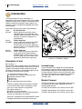
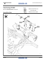
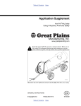
Figure 1
YP2425 and YP4025 DF Seeder
D
B
31088
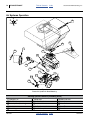
Description of Unit
Refer to Figure 1
The YP2425F-2470, YP4025F-1630 and YP4025F-1670
Planter is a dry fertilizer/seeder version of the YP2425 or
YP4025. The standard seed-only hopper or bulk-box
capability is replaced by a dual-function hopper (one for
the YP4025F and two for the YP2425F).
• The dry fertilizer function includes:
1 a 1440 liter (41 bu) hopper compartment with
2 integrated volumetric meter;
3 ground drive;
4 gear box; and,
5 frame-mounted fertilizer zone counters.
Fertilizer is applied whenever the planter is lowered
and in forward motion. Rate is controlled by range
gears and a crank adjuster on the gearbox.
• The seeder function is a:
6 670 liter (19 bu) compartment
that delivers seed to the standard YP24/YP40 airbox
and row unit seed meters (not shown).
Intended Usage
Use the YP2425F and YP4025F Dry Fertilizer/Seeder
only to apply dry granular fertilizer and/or plant seeds
compatible with Singulator Plus® or finger pickup meters.
Do not modify the planter for use with attachments other
than Great Plains options and accessories specified for
use with the YP2425F-2470, YP4025F-1630 and
YP4025F-1670.
Models Covered
This feature operator manual (403-362M) applies only to
these specific planter models equipped with the dry
fertilizer/seeder features:
YP2425F-2470 25-Series, Dry Fertilizer, 24-row, 70cm
YP4025F-1630 25-Series, Dry Fertilizer, 16-row, 30in
YP4025F-1670 25-Series, Dry Fertilizer, 16-row, 70cm
Seed rate is controlled by the standard DICKEY-john®
IntelliAg® seed monitor and hydraulic meter drive.
403-362M
Table of Contents
Index
2013-03-25
Great Plains Manufacturing, Inc.
Table of Contents
Index
Introduction
Document Family
Using This Manual
403-362M
Feature Supplement Manual (this manual)
401-406M
401-406P
401-406B
YP2425F:
Planter Operator Manual
Planter Parts Manual
Planter Seed Rate manual
This manual will familiarize you with
safety, assembly, operation,
adjustments, troubleshooting, and
maintenance. Read this manual and
follow the recommendations to help
ensure safe and efficient operation.
The information in this manual is current at printing.
Some parts may change to assure top performance.
401-571M
401-571P
401-571B
YP4025F:
Planter Operator Manual
Planter Parts Manual
Planter Seed Rate manual
DICKEY-john®
110011508
110011501
2013-03-25
7
Definitions
The following terms are used throughout this manual.
manuals:
Seed Monitor Manual Level 1
Seed Monitor Manual Level 2 and 3
A crucial point of information related to the preceding topic.
Read and follow the directions to remain safe, avoid serious
damage to equipment and ensure desired field results.
Note: Useful information related to the preceding topic.
Right-hand and left-hand as used in
this manual are determined by facing
the direction the machine will travel
while in use unless otherwise stated.
An orientation rose in some line art
illustrations shows the directions of:
Up, Back, Left, Down, Front, Right.
Table of Contents
Index
U
B
R
F
D
L
403-362M
8
YP2425F/YP4025F
Table of Contents
Index
Great Plains Manufacturing, Inc.
Index
2013-03-25
Preparation and Setup
This section helps you prepare the dry fertilizer feature of
your YP2425F-2470, YP4025F-1630 and YP4025F-1670
planter for use, and covers tasks that need to be done
seasonally, or when the tractor/planter configuration
changes.
Before using the planter in the field, you must hitch it to a
suitable tractor, inspect systems and level the planter,
per the instructions in the 401-406M (YP2425) or
401-571M (YP4025) Operator manual. Before using the
planter for the first time, and periodically thereafter,
certain adjustments and calibrations are required. See
the Operator manual for these procedures.
Initial Setup
See the Operator manual, Appendix B, for pre-delivery
and first-time setup items for the basic planter.
First-time/infrequent setup tasks for the
YP24/YP40 DF/seeder feature include:
• Verify monitor setup (page 53 in this manual).
Post-Delivery/Seasonal Setup
On initial delivery, use with a new tractor, and seasonally,
check and as necessary, complete these items before
continuing to the routine setup items:
• Inspect fertilizer meter door seals for leaks or wear.
• Inspect fertilizer meter flutes for damage or wear.
Hitching and Leveling
The YP24/YP40 DF/seeder feature causes no changes
to the hitching procedures described in the planter
Operator manual.
403-362M
Table of Contents
Great Plains Manufacturing, Inc.
Table of Contents
Index
9
Index
403-362M
Operating Instructions
This section covers general operating procedures.
Experience, machine familiarity, and the following
information will lead to efficient operation and good
working habits. Always operate farm machinery with
safety in mind.
Pre-Start Checklist
Perform the planter pre-start checklist, and the following
steps before transporting the YP24/YP40 DF/seeder
planter to the field. Add this item:
❑
Check for air system leaks at the fertilizer hopper lid,
meter, inlet and outlet manifolds.
Planter Folding and Raising
The YP24/YP40 DF/seeder feature does not affect
raising/lowering, folding/unfolding or tongue operations.
Material Loss Risk
The fertilizer ground drive operates whenever the planter is
lowered and in forward motion. If fertilizer application is not
desired (for example, during speed calibration or row unit
adjustment testing), take any of these steps to prevent fertilizer
metering:
▲ Tie ground drive wheel up out of ground contact.
▲ Remove a chain in the ground drive.
▲ Set meter gearbox adjuster to zero. Do this only on a
temporary basis, such as speed calibration.
▲ Defer loading of fertilizer until after speed calibration or
other non-application lowered movement.
2013-03-25
Table of Contents
10
YP2425F/YP4025F
Table of Contents
Index
Great Plains Manufacturing, Inc.
Transport
Loss of Control Hazard:
Ensure that the towing vehicle is adequate for the task. Using
an inadequate tow vehicle is extremely unsafe, and can result
in loss of control, serious injury and death.
21
The planter can weigh over 15 000 kg (33,500 pounds),
depending on configuration and material load. The tractor
unit MUST be rated for the load. If the tractor is not rated for
at least 15 000 kg, calculate or obtain a scale weight of the
planter.
5
Do not tow if planter exceeds the load rating of the vehicle.
Braking and Loss of Control Hazard:
Do not exceed 20 mph (32 kph).
Reduction of Control Risk:
Material loaded prior to travel increases stopping distance,
and increases the need for caution in turns and braking.
Typical YP2425F Weights
Configuration
YP2425-2470
Standard¹ Model, Empty
9200 kg
Std. Model, Full Hoppers
13000 kg
Maximum² Configuration, Full
13900 kg
¹ Includes: Markers and Frame-Mounted Coulters
² Adds: Unit-Mounted Coulters & Dual Row Cleaners
Typical YP4025F Weights
YP4025FConfiguration
-1670
-1630
Standard¹ Model, Empty
12800 kg
28200 lbs
Std. Model, Full Hoppers
14700 kg
32300 lbs
Maximum² Configuration, Full
15200 kg
33500 lbs
¹ Includes: Markers and Frame-Mounted Coulters
² Adds: Unit-Mounted Coulters & Dual Row Cleaners
Other than considerations of planter weight, the
YP2425F-2470, YP4025F-1630 and YP4025F-1670
requires no changes to transport compared to the
standard YP24/YP40. See the 401-406M or 401-571M
Operator manual for transport instructions.
403-362M
Table of Contents
Index
2013-03-25
Great Plains Manufacturing, Inc.
Table of Contents
Index
Operating Instructions
11
Loading Materials
Seed and fertilizer may be loaded manually or via auger.
Walkboard/ladder details, and auger height requirements
are shown in the Operator manual. Before ascending the
ladder for loading or auger outlet control:
• Check that the walkboard is closed and latched.
Although the YP40F walkboard has a side extension,
the latching is identical to the standard walkboard.
• Swing down and latch the lower ladder section.
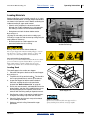
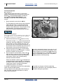
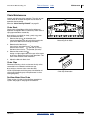
Refer to Figure 2
(depicting the side railing closed, and rear railing open)
If loading via auger, the side and rear top railings may be
swung down for clearance.
• Shut off hydraulic fan. Both hopper bins are
pressurized when the fan is running.
Figure 2
Walkboard Railings
31092
Blowing Debris and Possible Chemical Hazards:
Do not open hopper lids with fan running. Hopper contents
may blow into your face, possibly causing eye injury, and
exposing you to dust and possible chemical hazards.
Dust and Possible Chemical Hazards:
Seed may present a dust inhalation hazard. Treated seed may
present a chemical exposure hazard. Wear eye protection.
Wear a dust mask or respirator. Wear other protective
equipment specified by the seed and treatment suppliers.
Loading Seed
The seed hopper is the smaller rear hopper.
1
1. Close the slide gate at the base of the seed hopper.
2
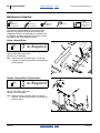
Refer to Figure 3
2. To open the lid, lift up on the handle 1 . The handle is
also a spring-loaded latch, and tilts up to release.
3. Inspect the hopper for leftover seed and debris.
Clean out anything other than the seed to be
planted. See “Material Clean-Out” on page 35
4. At first use, and seasonally, add seed lubricant to the
empty hopper, and then add a seed/lubricant mix to
the empty hopper per the Operator manual. Mix
lubricant with remaining seed per Operator manual.
Figure 3
Seed Hopper Lid
31091
5. See Caution at right. Load seed and seed lubricant
no higher than the top cap of the vent structure.
6. Close lid. Check that the latch snaps to horizontal
and is holding lid closed.
7. Swing up and latch railing if lowered for auger
operations.
2013-03-25
Sudden Lid Motion:
Open rear (seed) lid carefully. It is supported by a
spring-loaded piston, and may swing up rapidly.
Table of Contents
Index
403-362M
12
YP2425F/YP4025F
Table of Contents
Index
Great Plains Manufacturing, Inc.
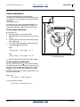
Loading Fertilizer
Check that calibration and clean-out doors are closed at
meter (page 35).
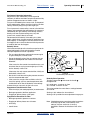
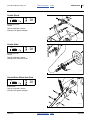
Refer to Figure 4
1. Lift the handle
U-bolt shackle
3 until
5.
the hook
2. Inspect the strainer basket
clean as necessary.
6
4
releases from the
for debris. Remove and
Confined Space Hazards:
Leave strainer in place for all routine operations. Do not
enter hopper for routine operations. Risk of entrapment
and rapid suffocation. See “Material Clean-Out” on
page 35 for further information.
3
6
7
5
3. Inspect the hopper for leftover fertilizer and debris.
Clean out anything other than the fertilizer to be
applied. See “Material Clean-Out” on page 35.
4. Re-install strainer.
4
5. Inspect the seal under the lid. It must make air-tight
seal against the hopper top plate 7 when the lid is
closed and latched. Replace seal if crushed, worn or
missing.
Figure 4
Fertilizer Hopper Lid
6. Load fertilizer through strainer.
31090
Dust and Possible Chemical Hazards:
Dry fertilizer may present a dust inhalation hazard and
may present a chemical exposure hazard. Wear eye
protection. Wear a dust mask or respirator. Wear any
other protective equipment specified by the material
supplier.
7. Swing lid closed. Lift handle. Engage shackle with
hook. Close handle.
8. Swing up and latch railing if lowered for auger
operations.
Close lid handle for operations or short-term parking. For
long-term storage, do not engage hook or latch handle,
to avoid deforming the seal.
For storage, particularly unlatched, a padlock through
both U-bolts deters unauthorized entry by persons
unaware of possible confined space risks, and prevents
entry of pests, debris and precipitation.
403-362M
Table of Contents
Index
2013-03-25
Great Plains Manufacturing, Inc.
Table of Contents
Index
Operating Instructions
13
Changing Seed Box or Hopper
This topic in the Operator manual does not generally
apply to the YP2425F-2470, YP4025F-1630 and
YP4025F-1670. Using a standard 82bu hopper requires
substantial disassembly of the planter seed cart
structure, and modifications to the air system. Using a
150bu hopper or dual 200 gallon liquid fertilizer system
further requires removal of the entire fertilizer ground
drive. Such conversions are not documented or
recommended.
2013-03-25
Table of Contents
Index
403-362M
14
YP2425F/YP4025F
Table of Contents
Index
Great Plains Manufacturing, Inc.
Air Systems Operation
U
B
R
F
D
5
L
6
8
1
2
7
9
3
10
11
4
12
13
14
15
Figure 5
Planter Air System for Seed Metering
31094
Seeding System Elements (Excluding Drive)
1
Hydraulic Fan
6
Slide Gate
11
Meter Inlet Vent
2
Fan RPM Sensor
7
Air Box Seed Inlet
12
Seed Meter
3
Butterfly Valve (Seed Leg)
8
Seed Level Sensor
13
Meter Drive
4
Manifold Air Inlet
9
Air Box Manifold Outlet
14
Seed Tube
5
Seed Hopper
10
Seed Delivery Hose
15
Seed Sensor
403-362M
Table of Contents
Index
2013-03-25
Great Plains Manufacturing, Inc.
Table of Contents
Index
Operating Instructions
15
Seeding System Overview
Refer to Figure 5 on page 14
1. Hydraulic Fan:
The hydraulic fan supplies air for both seed and
fertilizer delivery. Fan rpm is operator-adjusted via
the tractor circuit’s hydraulic flow control.
2. Fan RPM Sensor:
Fan rpm is measured by a sensor mounted inside
the fan cage, and reported on the seed monitor
console.
3. Butterfly Valve (Seed Leg):
Manually-adjusted butterfly valves are provided on
the splitter at the fan outlet. The valve on the left leg
controls air for the seeding system. See page 19 for
valve adjustment.
4. Air Box Air Inlet:
Fan air enters the air box at the manifold inlet and is
mixed with seed.
5. Seed Hopper:
The rear hopper is the seed hopper. See “Loading
Seed” on page 11. The hopper contains a
pressure-balancing system (not shown) to help
prevent seed bridging.
6. Slide Gate:
There is a slide gate at the base of the seed hopper,
used to shut off seed flow during transport,
maintenance and storage.
7. Air Box Seed Inlet:
Seed enters the air box manifold at the top.
8. Seed Level Sensor:
The inlet contains a level sensor. When this sensor is
exposed (seed level below sensor), there may be
less than a hectare of seed remaining.
9. Seed Manifold Outlets:
The fan airflow entrains seed inside the air box, and
exits at the manifold outlets. On this model planter,
there is one outlet port per row.
2013-03-25
10. Seed Hoses:
Seed hoses deliver seed to the rows. On this model
planter, there is one hose per row, and no Y-tube
splitters.
11. Air Release Vents:
The meter inlets contain a venting system to exhaust
the delivery air. When seed backs up above the vent,
seed flow to that row stops until the meter has
consumed enough seed to re-expose the vent.
12. Seed Meter:
The Singulator Plus® or finger pickup meter contains
a seed wheel or finger-set that capture seeds at a
precise rate.
13. Seed Meter Drive:
Meter rotation is coupled to the drive system, which
is powered by a hydraulic motor (not shown) under
control of the seed monitor. Clutches control drive
shafts for entire planter sections. See planter
Operator manual for clutch operation.
Note: Seeding rate is independent of air system
operation, if the air system is set to provide
enough bulk seed flow to keep the meters full, but
not so much flow that system plugging occurs.
See page 19 for fan operation.
Note: A coupler at the meter may be disengaged to shut
off seeding at that row. See planter Operator
manual for row shut off. Fertilizer application
cannot be shut off at individual rows.
14. Seed Tube:
The seed wheel or finger set deposits seed in the
row’s seed tube, for delivery to the furrow.
15. Seed Sensor:
In the seed tube, the seed sensor detects passage of
seeds. Medium size and large seeds are counted
individually. With smaller seeds, most are detected,
allowing the monitor to detect stoppages.
Table of Contents
Index
403-362M
16
YP2425F/YP4025F
Table of Contents
Index
Great Plains Manufacturing, Inc.
U
F
5
B
R
L
D
6
1
2
3
7
11
3
12
3
}
2
3
3
8
16
4
2
13
10
18
3
14
15
9
3
2
17
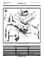
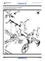
Figure 6
Planter Air System for Fertilizer Metering
31093
Fertilizer System Elements (Excluding Drive)
1
Hydraulic Fan
7
Level Sensor
13
Manifold Outlets and Hoses
2
Fan RPM Sensor
8
Fertilizer Meter
14
3-Way Tower
3
Butterfly Valve (Fertilizer Leg)
9
Calibration/Clean-Out Doors
15
2-Way Tower
4
Air Inlet Manifold
10
Meter Shaft RPM Sensor
16
2-Way Air Vent
5
Seed Hopper
12
Flute Stars
17
Blockage Detector
6
Pressure Sensor
11
Range Gears
18
Coulter Applicator
403-362M
Table of Contents
Index
2013-03-25
Great Plains Manufacturing, Inc.
Table of Contents
Index
Operating Instructions
17
Fertilizer System Overview
Refer to Figure 6 on page 16
1. Hydraulic Fan:
The fan supplies air for both fertilizer and seed
delivery. Fan rpm is operator-adjusted via the tractor
circuit’s hydraulic flow control.
2. Fan RPM Sensor:
Fan rpm is measured by a sensor mounted inside
the fan cage, and reported on the seed monitor
console.
Fertilizer metering occurs whenever the planter is
lowered and in forward motion.
12. Flute Stars:
Fertilizer is metered into the manifold air stream by
flutes on the final shaft. The four inside
compartments have three flutes (six halves) and feed
3-way towers. The two outside compartments have
two flutes and feed 2-way towers.
3. Butterfly Valve (Fertilizer Leg):
Manually-adjusted butterfly valves are provided on
the splitter at the fan outlet. The valve on the right leg
controls air for the fertilizer system. See page 19 for
valve adjustment.
Material Mis-Application Risk:
If it is ever necessary to disconnect delivery hoses at the
manifold, it is essential that the hoses to the wing-end
(2-way) towers be connected to the outside ports
(#1 and #6) at the manifold.
4. Fertilizer Air Inlet Manifold:
Fan air is divided into six equal flows at the inlet
manifold.
5. Fertilizer Hopper:
The front hopper is the fertilizer hopper. See
“Loading Fertilizer” on page 12. The hopper
contains a ladder-style pressure-balancing system
(not shown) to help prevent fertilizer bridging.
6. Pressure Sensor:
A sensor in the fertilizer hopper reports air pressure
to the seed monitor, and is reported on the console.
7. Fertilizer Level Sensor:
The fertilizer hopper contains a level sensor. When
this sensor is exposed (fertilizer level below sensor),
approximately 78 liters (2.2 bu) of fertilizer remains.
8. Fertilizer Meter:
The fertilizer meter is at base of the fertilizer hopper.
There is no slide gate. The meter is always open to
the fertilizer hopper.
9. Meter Doors:
The meter box has doors at the bottom for clean-out
(front) and calibration (rear). See page 27 or
page 35. These doors are closed for field operations.
10. Fertilizer RPM Sensor (shaft monitor):
A sensor on the meter flute shaft reports shaft rate to
the seed monitor. The seed monitor does not report
material rate from this data, but can generate alarms
on shaft stoppages or rpm out-of-limits.
11. Range Gears:
Interchangeable Final Range Gears set the coarse
rate of the flute shaft. The meter system is powered
by a ground drive (not shown), which has a variable
rate gearbox for fine adjustment. See page 23.
2013-03-25
13. Fertilizer Manifold Outlets:
The fan airflow from the inlet manifold entrains
metered fertilizer in the chambers below the flutes,
and exits at the manifold outlets. Each outlet serves
a single hose to a single distribution tower, and
multiple rows.
The center four outlets serve 3-way towers.
The outside two outlets serve 2-way towers.
14. 3-way Tower:
Four of the six towers divide the air/fertilizer flow
3 ways.
15. 2-Way Tower:
Two of the six towers (the two serving wing end
rows) divide the air/fertilizer flow 2 ways.
16. Vent for 2-Way Towers:
To balance the airflow at all manifold ports, the 2-way
towers vent some of the air at the tower inlet. See
page 43 for maintenance.
17. Blockage Detectors:
Each tower divider outlet is equipped with a material
sensor, connected to the seed monitor and
configured for “Blockage” mode. These report any
flow failure at the rows. See page 54.
18. Coulter Applicators:
Coulters are factory configured for side-dress
fertilizer application, at 5cm (2in) off-row, and a
depth of 5cm (2in), “zone” application. The coulter
has adjustments for depth and the height of the
applicator exit tube.
Table of Contents
Index
403-362M
18
YP2425F/YP4025F
Table of Contents
Index
Great Plains Manufacturing, Inc.
Fan Circuit Operation
Refer to Figure 7
Three hydraulic hoses serve the fan, and must be
properly connected for the fan to operate in the correct
direction 1 , at recommended speeds, and without
damage. See “Hydraulic Hose Hookup” in the
401-406M (YP24) or 401-571M (YP40) Operator
manual.
1. Always connect the case drain line
2
2
3
4
first.
This line protects the outer shaft seal of the hydraulic
motor. The case drain is a small line to the hitch,
provisioned with a specialized low-seep flat-face
case drain Quick Disconnect. Pressure spikes during
motor operation, and pressure cycles due to
temperature change are bled off by the case drain.
5
1
Motor Seal Damage Hazard
Do not apply pressure to the case drain line. Do not change the
special QD connector. A restricted or sealed case drain line
will promptly result in motor seal damage.
2. Connect the motor return line 3 second, to sump.
Figure 7
Hydraulics at Fan
31095
The planter includes a 11⁄16in low back-pressure QD
coupler set. Install the receptacle on a tractor sump
port, and not at a normal remote return port. The
unusual size aids in ensuring correct connection, so
that the motor return line handles high volume at low
back-pressure, ensuring full motor performance.
3. Connect the motor inlet line 4 to a tractor remote
capable of 95 liters per minute (25 gpm). If a priority
remote is available, use it for the fan.
4. The fan hydraulic circuit includes a check valve 5 ,
which provides a relief path for oil at motor shutoff.
If the fan is connected in reverse, flow through this
valve results in low fan rpm, providing strong
indication reversed connection.
If the fan is connected in reverse, it may not run at all
(due to no oil source at the return connection). If oil is
present, oil bypass at the check valve 5 prevents the
fan from reaching high rpm. A reversed fan may send
some air to the delivery systems, but is incapable of
providing reliable air flow for planting.
Correct fan direction is shown at 1 . If reversed fan is
suspected, observe it during shutoff, as the direction
of motion is easier to see at lower rpms as it slows to
a stop (initial startup is virtually instantaneous,
making observation at start difficult).
Fan speed is controlled by the tractor circuit and butterfly
valves (and not the seed monitor).
You may stop the fan by setting the circuit to neutral or
float. The check valve slows the blades to a stop by
locally recirculating the oil.
403-362M
Fan speed can change as oil heats to operating
temperature. Re-check fan rpm and hopper pressure
more often during early operations.
Table of Contents
Index
2013-03-25
Great Plains Manufacturing, Inc.
Table of Contents
Index
Operating Instructions
19
Fan General Operating Information
Adjust the fan rpm and butterfly valves to provide
sufficient air flow for consistent transport of seed and dry
fertilizer. Suggested values are shown at right.
Fan rpm is controlled by the tractor circuit, and reported
by the seed monitor. Always start the fan with a low flow
setting. Gradually bring fan up to the target rpm.
Fan air pressure is measured by a sensor in the fertilizer
hopper, and reported by the seed monitor. Air pressure is
controlled by fan rpm, butterfly valve settings, material
density and rates. System settings may vary with
material mix, material density and rates.
Recommend initial butterfly valve setting is 0° (wide
open) at both valves (assuming material application from
both hoppers). If one hopper is unused, set the valve for
that hopper to 30° to simulate the normal back-pressure
of material flow from that hopper.
Butterfly Valves
Use tractor remote hydraulic valve flow control to set fan
speed and butterfly valves to balance flow. Precise
technique depends on tractor capabilities:
70°
• For any setup adjustment, operate the tractor engine
at typical field rpms, and not at idle.
45°
• Preset the butterfly valves. Use any settings that you
previously developed for the material mix and rates,
otherwise:
2
20°
If the tractor has fine control of remote flow rates, and
consistent flow at varying tractor engine rpm, initially
set the butterfly valves to 0°.
1
If the tractor has only coarse control of flow, initially set
the butterfly valves to 45°.
• Set the fan circuit flow to bring the pressure sensor to
near the recommended value.
• If the tractor has marginal flow available, or the list
circuit has priority, you may need to experiment with
combinations of fan flow and butterfly valve settings.
Figure 8
Fan Butterfly Valve Handle
Butterfly Valve Operation:
To adjust, loosen bolt 1 and rotate the handle
Re-tighten bolt.
25137
2.
At excessive rpm, too much air flow can cause:
0° is wide open - maximum air flow.
90° is closed - minimum air flow.
Symptoms of Insufficient Air Flow
• Excessive skips (low seed population) at seed meters.
The valve provides the most effect at settings between
20° and 70°.
• Blockage reported at fertilizer applicators.
Starting at 30° reduces the fan workload.
Starting at 45° provides the most adjustment range up or
• Plugging of delivery hoses at low spots.
Symptoms of Excessive Air Flow
• Blockage reported at openers or coulters.
• Plugging of delivery hoses near air boxes.
• oil heating
• slow lift times
2013-03-25
Note: If desired pressure cannot be reached, or requires
unusually high oil flow at low butterfly valve
settings, chances are the fan is running
backwards. Reverse the inlet/return lines at the
hitch.
Table of Contents
Index
403-362M
20
YP2425F/YP4025F
Table of Contents
Index
Great Plains Manufacturing, Inc.
Index
2013-03-25
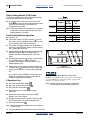
Monitor Operation
The YP2425F-2470, YP4025F-1630 and YP4025F-1670
includes the standard DICKEY-john® IntelliAg® monitor,
operating in Planter/Drill Control mode. There are setup
differences vs. other YP40 planters, generally:
• Row delivery tubes are equipped with blockage
sensors. These rows are treated as “seed” rows
numbered from
YP24
YP40
25 (actual seed row 1) to 17 (actual seed row 1) to
48 (actual seed row 24)
32 (actual seed row 16)
• Seed tubes are monitored in Population mode.
Fertilizer applicators are monitored in Blockage mode.
Note: Fertilizer is not set up as a separate Material or
Channel. The monitor’s “GRAN FERT” air drill
mode is not used. The seed monitor is not
engaged for fertilizer calibration, and no
“CAL CONST” is required.
• There are two hopper level sensors in use:
1. Seed air box
2. Fertilizer hopper level
Note: There is no optional level sensor for the seed
hopper.
• There is one air pressure sensor in use, installed in
the fertilizer hopper.
• There is a seconda rpm sensor, installed on the left
end of the fertilizer meter shaft. Although the seed
monitor can report the rpm, the main use is as a shaft
monitor.
Set upper and lower rpm limits based on the fertilizer
rate chart, and your planned field speed. The chart
shows expected meter rpm for various gearbox
settings, in High and Low range, at 9.7 kph (6 mph). If
using a different field speed, adjust the expected rpm
proportionately.
Marker Operation
The YP24/YP40 DF/seeder feature does not affect
marker operations.
a. The first rpm sensor is on the hydraulic motor for the seed meters.
403-362M
Table of Contents
Great Plains Manufacturing, Inc.
Table of Contents
Index
Operating Instructions
21
Field Set-Up Checklists
Field Operation
Add the following items to the basic planter checklists, or
any customer checklist you have developed.
The YP24 DF/seeder feature requires no changes to the
checklists in the 401-406M Operator manual, the YP40
DF/seeder requires no changes to the checklists in the
401-571M Operator manual.
When the fan is running, and the planter is lowered and
in forward motion, material is applied from the fertilizer
hopper at the currently set rate.
Consult seed monitor for blockage alarms.
When reloading fertilizer, check consumption against
anticipated use to that point.
Mechanical Checklist (Hitching)
Page
No changes
Electrical Checklist
Page
No changes
Hydraulic System Checklist
Page
No changes
Mechanical Checklist (post-Hitching)
Page
No changes
Page
Check fertilizer ground drive and gearbox
output chain lubrication and slack
Check final Range gears set for desired
High or Low range
Check setting of variable rate gear box
against chart or calibrated rate.
No changes for seeding
39
The YP24 or YP40 DF/seeder feature adds the following
steps to the storage recommendations of the 401-406M
or 401-571M Operator manual:
• Perform a seeding system clean-out (page 35)
23
• Close the lid of the seed hopper firmly, making sure it
is fully latched (page 11).
24
• Clean-out the fertilizer air system and hopper
(page 35).
• Tie the clean-out and calibration doors partly open
(page 35).
Air System Checklist
Page
Fan butterfly valves set for fertilizer
Fertilizer loaded. Lid closed.
No air leaks in fertilizer system
Hoses and tubing - no sags, no pinches
Hoses fully connected to applicators
19
12
Row Units Checklist
Page
2013-03-25
The YP24 or YP40 DF/seeder feature requires no
changes to the Parking steps in the 401-406M or
401-571M Operator manual.
Long-Term Storage
Planter Meter Drive Checklist
Check frame-mounted coulter:
offset
angle
depth
Check applicator height.
Short-Term Parking
• Close, but do not tightly seal the fertilizer hopper lid
(page 12).
Equipment Damage Risk:
Perform a fertilizer clean-out when the planter is left unused
for more than 36 hours. Fertilizer is generally very corrosive.
If fertilizer or residue is allowed to remain in the hopper or
meter, exposed metal surfaces will be attacked. See “Material
Clean-Out” on page 35.
29
29
Table of Contents
Index
403-362M
22
YP2425F/YP4025F
Table of Contents
Index
Great Plains Manufacturing, Inc.
Adjustments
This table provides a cross-reference to all adjustment
items unique to the YP2425F-2470, YP4025F-1630 and
YP4025F-1670 planter.
For adjustments not listed, see the 401-406M (YP24) or
401-571M (YP40) Operator manual.
Adjustment
Air Systems
Page
The Adjustment Affects
14
Fan Speed
19
Optimal seed distribution
Butterfly Valve (Seed Leg)
19
Consistent seed flow and disk singulation
Butterfly Valve (Fertilizer Leg)
19
Material Rates
Seed Rate
Seed Rate
Fertilizer Rate
401-406B
(Same as for standard YP24 planters.
Refer to that Seed Rate manual.)
401-571B
(Same as for standard YP40 planters.
Refer to that Seed Rate manual.)
62
Monitor Adjustments
Alarms
20
Restore factory settings
53
Frame-Mounted Coulter Adjustments
Coulter Depth
29
Applicator Depth
29
403-362M
Table of Contents
Index
2013-03-25
Great Plains Manufacturing, Inc.
Table of Contents
Index
Adjustments
23
Setting Material Rates
Setting Seed Rate
Seed rate setting for the YP2425F-2470, YP4025F-1630
and YP4025F-1670 planter is identical to the standard
YP24 or YP40 planter. Refer to the Operator and Seed
Rate manuals for details:
YP2425F-2470
401-406M Operator manual
401-406B Seed Rate manual
YP4025F-1630 or 401-571M Operator manual
YP4025F-1670
401-571B Seed Rate manual
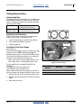
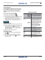
Setting Dry Fertilizer Rate
There are three steps to obtaining the target fertilizer
kilograms per hectare (or pounds per acre):
1. Set Final Drive Range on fertilizer meter (below)
2. Set Variable Rate Gearbox (page 24)
2
3. Calibrate (page 25).
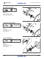
3
DRIVING
Seed Meter Final Drive Range
4
Refer to Figure 9
The meter flute shaft 1 is driven by the agitator shaft 2
through a pair of interchangeable gears 3 , 4 . The
positioning of these gears creates two final drive ranges.
DRIVEN
1
The rate chart has two page columns, each based on a
specific Final Drive Range. The Ranges are:
• “High” range, which is used for higher fertilizer rates
Figure 9
High Final Drive Range
• “Low” range, which is used for lower fertilizer rates
The two meter shafts are labeled “DRIVING” and
“DRIVEN”.
The “DRIVING” shaft is the upper shaft.
The “DRIVEN” shaft is the lower shaft.
Refer to the Fertilizer Rate chart (page 63), the table at
right, and Figure 9 for setting the meter final drive range.
FINAL DRIVE
RANGE
LOW RANGE
HIGH RANGE
91097
DRIVING
DRIVEN
17 Tooth Small
54 Tooth Large
54 Tooth Large
17 Tooth Small
1. Remove the lynch pins from the ends of both shafts.
2. Remove and position the gears as shown in the table
above.
3. Secure with lynch pins.
2013-03-25
Table of Contents
Index
403-362M
24
YP2425F/YP4025F
Table of Contents
Index
Great Plains Manufacturing, Inc.
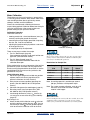
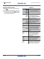
Setting Variable Rate Gearbox
The variable rate gearbox allows an infinitely variable
meter drive speed to attain a wide range of application
rates. The ratio of gearbox input speed to output speed is
controlled by the position of a gearbox control arm. The
control arm has an indicator that points to a scale
marked in degrees. The Fertilizer Rate chart shows the
rate for each five degrees of arm rotation.
1
Refer to the rate chart and set the variable rate gearbox
control arm to its scale setting for the target fertilizer rate
3
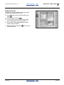
To adjust the Variable Rate Gearbox:
Refer to Figure 10
1. Remove the hairpin cotter
adjustment crank 2 .
1
securing the gearbox
2
2. Rotate crank 2 until the control arm indicator 3
points to the scale setting that matches the rate from
the rate chart or as determined by calibration.
Figure 10
Variable Rate Gearbox
31099
3. Reinsert the hairpin cotter.
Note: The variable rate gearbox operates optimally
between 30 and 70. If the target fertilizer rate
appears on both the Low and High Range charts,
the most consistent results are obtained when the
gearbox control arm is set between 30 and 70.
Settings below 20 degrees are not recommended.
When the control arm is set above 70 degrees,
large movements of the arm result in small
changes in seeding rate.
403-362M
Table of Contents
Index
2013-03-25
Great Plains Manufacturing, Inc.
Table of Contents
Index
Adjustments
25
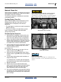
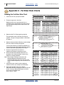
Meter Calibration
The fertilizer rate charts are based on a representative
11-52-0 dry granular fertilizer. Many factors affect meter
rates including fertilizer density, granularity, texture,
adhesion, humidity and field conditions.
2
Great Plains recommends calibrating for the exact
material being applied. Calibration determines the kg/ha
(or lbs/ac) of the meter at the current variable rate
gearbox setting for your particular fertilizer.
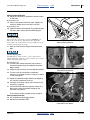
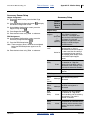
Calibration Procedure
Calibration consists of:
• metering material for a simulated distance (area), by
manually cranking the ground drive system,
1
• measuring the sample weight generated, computing
the rate, and, if not the rate desired,
• adjusting the gearbox setting to produce a rate closer
to the target rate, then;
Figure 11
Calibration Cranking
• re-sampling to verify the adjustment.
31000
There are two ways to collect the sample:
a. Fan On / Row Sample (page 26)
Place collection containers under each fertilizer row
applicator (calibration door closed).
b.
Fan Off / Meter Sample (page 27)
Place a tarp under the fertilizer meter with the
calibration door open.
Either method relies on manual operation of the fertilizer
ground drive system and meter. You may operate the
drive by turning the ground drive wheel itself, or use the
supplied 403-414H crank to turn the jackshaft at the
ground drive arm pivot.
Initial Calibration Steps
1. Set the final gear Range and variable rate gearbox
adjuster (from the charts on page 64 or 65, or
previous calibrations of similar material).
2. Hitch planter to tractor capable of operating the
planter. (See 401-406M or 401-571M Operator
manual.)
3. Close the slide gate on the seed hopper (page 14).
4. Raise the planter. Install transport locks. (See
401-406M or 401-571M Operator manual.)
5. Load enough fertilizer for at least 1⁄10 hectare (or
1⁄ acre) plus an extra 35 to 45 kg (75 to 100 lbs)
10
(page 12).
Refer to Figure 11
6. Attach the 403-414H calibration crank 1 to the left
end of the fertilizer ground drive arm pivot. You can
use the hairpin cotter 2 from the gearbox adjuster
crank to secure the calibration crank to the shaft.
2013-03-25
Sampling Error Risk:
Do not leave fertilizer hopper lid open. Low pressure above
fertilizer skews results. Perform calibration with lid tightly
closed, as for normal field operations.
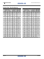
Revolutions for Sample Size
Sample
Size
Revolutions of:
Crank
Wheel
1/10th Hectare
4.52
5.24
1/10th Acre
11.16
12.95
1 Hectare
45.2
52.4
1 Acre
111.6
129.5
31104
Note: A cranking speed of 1 revolution per second
(60 rpm) simulates a field speed of 9 kph.
Note: For a more accurate calibration, crank for a full
hectare or acre. Make sure there is enough
material in the hopper.
Material Rate Risk:
Check consumption rates in the field. One variable factor that
calibration cannot compensate for is the effective rolling
radius of the ground wheel in unusually soft or hard ground.
Table of Contents
Index
403-362M
26
YP2425F/YP4025F
Table of Contents
Index
Great Plains Manufacturing, Inc.
Row Sample Calibration
This method requires 16 or 24 containers each with a
capacity of about 1% of a hectare or acre, and a scale
capable of precisely weighing the heaviest empty
container plus the sample size (or all the containers at
once).
7. Turn on the seed monitor system. Although not used
for calibration, you need the monitor to display fan
rpm.
8. Weigh the empty sample containers (the “tare”).
Refer to Figure 12
9. Place the collection containers under each coulter
applicator.
Refer to Figure 13
10. Start the hydraulic fan. Adjust the rpm to normal field
values.
Figure 12
Row Sample Collection
31102
Machine Damage Risk:
Do NOT turn the crank clockwise, or the gearbox may be
damaged. Turn the crank only counter-clockwise (as seen from
planter left, facing planter right).
11. Turn the crank counter-clockwise until material is
consistently appearing in the collection containers.
Stop cranking.
12. Empty the collection containers.
3
13. Turn the crank for the number of revolutions
necessary to simulate the area to sample, as shown
in chart on page 25.
14. Calculate the material rate per the instructions and
examples on page 28.
15. If the results differ from your target by more than a
few percent, adjust the gearbox setting per the
instructions on page 28.
Figure 13
Calibration Crank (Row)
Then measure another sample starting at step 13.
Row Sample Close-Out
16. Pin the gearbox adjuster
3
31000
in position
17. Remove the calibration crank.
403-362M
Table of Contents
Index
2013-03-25
Table of Contents
Great Plains Manufacturing, Inc.
Index
Adjustments
27
Meter Sample Calibration
18. Weigh any container(s) required to hold the sample
on the scale.
Refer to Figure 14
19. Place a tarp under the fertilizer meter. Support the
corners or edges so that no material can spill.
Refer to Figure 15
20. Open the meter calibration door. The calibration door
is the rear door, furthest from the DRIVING gear.
Material Loss Risk:
Do not open the (forward) door under the DRIVING gear.
This is the clean-out door. Opening this door drains the
hopper. Once the clean-out door is open it is difficult to stop
seed flow until the hopper is empty.
21. Wipe all material off the flanges around the meter
door.
Figure 14
Meter Sample Collection
31105
Figure 15
Calibration Door Handles
31101
Machine Damage Risk:
Do NOT turn the crank clockwise, or the gearbox may be
damaged. Turn the crank only counter-clockwise (as seen from
planter left, facing planter right).
Refer to Figure 16
22. Turn the crank counter-clockwise until material is
consistently appearing in the collection containers.
Stop cranking.
23. Empty the tarp and return it to the collection position.
24. Turn the crank for the number of revolutions
necessary to simulate the area to sample, as shown
in chart on page 25.
25. Weigh the collected sample. Subtract the weight of
any container required at the scale.
26. Calculate the material rate per the instructions and
examples on page 28.
27. If the results differ from your target by more than a
few percent, adjust the gearbox setting per the
instructions on page 27.
3
Then measure another sample starting at step 23.
Meter Sample Close-Out
28. Pin the gearbox adjuster
3
in position
29. Remove the calibration crank.
Figure 16
Calibration Crank (Meter)
2013-03-25
Table of Contents
Index
31000
403-362M
28
YP2425F/YP4025F
Table of Contents
Calibration Adjustment
Once a sample has been taken, two steps remain:
a. Calculate the current rate.
b.
If needed, calculate and apply an adjustment to the
gearbox setting.
Calibration: Rate Calculation
30. If not already done, weigh the metered sample. This
is the gross weight.
31. Subtract the weight of the empty containers (the
tare) from the gross weight.
Net_Weight = Gross_Weight – Tare
If your sample size was based on cranking for a full
hectare or acre, no further rate calculation is necessary.
The net weight is the per-hectare or per-acre rate. Skip
to step 33.
32. If the sample size was 1⁄10th ha (or ac), calculate the
rate for the full area.
Area_Rate = Net_Weight × 10
Calibration: Gearbox Adjustment
33. If the calculated rate is within about 2% of your
target, there may be no benefit in attempting further
calibration. Resume at “Row Sample Close-Out” on
page 26 or “Meter Sample Close-Out” on page 27.
Index
Great Plains Manufacturing, Inc.
Example based on YP4025-1670:
The example in this column is based on a target rate:
120 kg/ha
a gearbox setting of:
80
and a row sample, using 16 containers.
When empty the collection of 16 containers weighs:
1.1 kg
Example:
The sample and all containers weighs a total of:
12.6 kg
The net weight of the sample is:
12.6 - 1.1, or:
11.5 kg
Example:
Area rate for the sample is:
11.5 x 10, or:
115 kg/ha
This is just approximately 4% under the desired rate,
and is probably worth adjusting for.
34. Calculate a gearbox scale adjustment. Divide the
targeta rate by the sampled rate.
Example:
120 ÷ 115 is:
1.043 or 104.3%
Target_Rate
Factor = ----------------------------Area_Rate
35. Use this factor to determine the next gearbox setting.
Next_Setting = Previous_Setting × Factor
Example:
80 x 1.043 is:
83.5
36. Reset the gearbox adjuster to the “Next_Setting”
value.
For corrections of 5% or more, re-calibration is
recommended.
If a Low range correction puts the “Next_Setting” above
90, start settings development over in High range.
If a High Range correction puts the “Next_Setting” below
20, start settings development over in Low range.
Note: The gearbox adjustment has a near-linear effect
on rates only near mid-scale or for small
adjustment changes. For corrections of 10% or
more, or near the ends of the scale, recalibration
is essential, as further adjustment is likely.
a. Use the desired field application rate. Do not use any “adjusted” rate used to determine the initial gearbox setting.
403-362M
Table of Contents
Index
2013-03-25
Great Plains Manufacturing, Inc.
Table of Contents
Index
Adjustments
29
Coulter Adjustment
The frame-mounted coulters standard on the
YP2425F-2470, YP4025F-1630 and YP4025F-1670 are
configured for “zone” application: 5cm offset from seed
furrow, and
5cm depth, or “2x2”in.
As blades wear, or under unusual field conditions, you
may need to adjust the coulter depth. If the depth is
adjusted, the applicator needs to be adjusted as well.
4
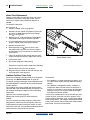
Coulter Height Adjustment
Refer to Figure 17
1. Raise the planter. Install transport locks.
2. Move the planter to a flat level surface. A paved area
is ideal.
1
3. At each coulter, measure the raised tool bar height
(“Bar_Height”) 1 .
4. For a 2.5cm (2in) coulter depth, compute the ideal
raised height 2 of the disk edge.
Metric:
2
Edge_Height = Bar_Height – 66 – 5
3
Inch:
Figure 17
Dry Fertilizer Coulter
Edge_Height = Bar_Height – 26 – 2.5
31109
5. Reset the coulter shank to the new “Edge_Height”.
Coulter Applicator Adjustment
Normally, the coulter tine tip 3 is set to exactly ground
level, although you may set it higher or lower for unusual
conditions. To change the height, loosen the mounting
bolt 4 and move the applicator weldment up or down.
If you are adjusting the tine height, to ground level, with
the planter raised, use:
Metric (cm):
Tine_Height = Edge_Height + 5
or, U.S. customary (inches):
Tine_Height = Edge_Height + 2.5
2013-03-25
Table of Contents
Index
403-362M
30
YP2425F/YP4025F
Table of Contents
Index
Great Plains Manufacturing, Inc.
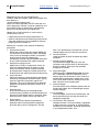
Frame-Mounted Coulter Force
In normal operation at target running depth, the spring is
at full extension or only slightly compressed. It
compresses briefly as obstructions and denser soil are
encountered.
Coulter springs are set to 181 kg (400 lbs). In normal
operation at target running depth, the spring is at full
extension. It compresses briefly as obstructions are
encountered.
• In heavy no-till conditions, you may observe the
springs in compression most of the time. This means
that the blades are not reaching the desired coulter
depth. If implement weight is sufficient, you can
increase the spring down-force to compensate.
• In light but rocky conditions, the factory spring setting
may be higher than needed. You can extend blade life
by reducing the force at which the blades ride up over
obstructions.
To adjust the coulter spring:
Refer to Figure 18
1. Raise the planter and install transport locks.
2. Determine the new spring length
table at right.
1
Figure 18
Frame-Mounted Coulter Spring
desired. See the
Spring Length
3. Measure the current length of the spring(s) to be
changed. If already shorter than 24.8cm (93⁄4in), or
longer than 26cm (101⁄4in), do not further adjust
them.
4. Loosen the jam nut
2
.
27139
1
Force at Blade
26.0 cm (10.25 in)
25.4 cm (10.00 in)
24.8 cm (9.75 in)
136 kg (300 lbs)
181 kg (400 lbs)
238 kg (525 lbs)
5. Rotate the adjuster nut 3 until the spring is at the
new length. Tighten the jam nut.
Note: If all springs are continuously in compression, the
coulters can lift the wing frames off the ground (at
the gauge wheels), resulting in uneven coulter
depth and/or uneven seed depth. If the planter is
already operating at maximum down-pressure,
reduce coulter depth.
403-362M
Machine Damage Risk:
Do not use spring lengths shorter than 24.8 cm (9.75 in). It
may contribute to premature parts failure which will not be
covered by warranty.
Table of Contents
Index
2013-03-25
Table of Contents
Great Plains Manufacturing, Inc.
Index
31
Troubleshooting
The tables of this section cover possible issues specific
to the YP24/YP40 DF/seeder feature.
See also the Troubleshooting section of the 401-406M or
401-571M Operator manual.
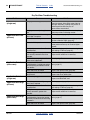
Dry Fertilizer Troubleshooting
Problem
Delivery Hoses
Plugging
No Fertilizer Flow
(all rows)
Cause
Solution
Insufficient airflow to operate both
fertilizer and seed delivery systems.
Increase fan speed (page 19).
If already at 3800 rpm, open fertilizer-leg
butterfly valve (page 19).
Fan circuit running in reverse
Check and re-connect circuit hoses (see
401-406M or 401-571M Operator manual).
Fan won’t run fast enough at
maximum tractor circuit setting
Check butterfly valves. Notes that tractor must
be able to supply 18 gallons/minute at 200 psi.
Fan speed low on capable tractor.
Hydraulic fan check valve is installed
backwards
Reverse installation of check valve (see
401-406M or 401-571M Operator manual).
Air leaks
Check:
hopper lid,
hopper base to airbox seal,
clean-out and calibration door seals and
delivery hoses.
False-positive blockage detection.
Shut off monitoring for fertilizer rows.
Some fine materials and/or low rates,
may cause the monitor to report
blockage.
Gearbox set to zero
Set and calibrate gearbox (page 24).
Gearbox at zero, even though not set Check that gearbox indicator arm is pinned to
to zero.
adjuster shaft.
Drive chain broken or skipping
Check chain condition and slack (page 39).
Material run-out.
Re-load fertilizer. Re-check rate setting and
level sensor function if run-out was
unexpected.
Bridging in fertilizer hopper due to air Inspect seal under lid. Replace as necessary.
leak
Check that hook and shackle have not become
mis-adjusted.
No Fertilizer Flow
(some rows)
2013-03-25
Bridging in fertilizer hopper due to
material consistency
Clean-out and replace material. See page 35.
Meter box completely plugged.
Clean-out hopper and meter. See page 36.
Butterfly valve closed at fertilizer leg
Check setting of valve. Tighten bolt.
Blockage inside tower.
Remove cap. Clear blockage.
Table of Contents
Index
403-362M
32
YP2425F/YP4025F
Table of Contents
Index
Great Plains Manufacturing, Inc.
Dry Fertilizer Troubleshooting
Problem
No Fertilizer Flow
(single row)
Application Rate Low
(all rows)
Cause
Solution
Bridging at inlet of applicator tube
Remove hose. Clear bridge. Check material for
oversize content. Also check meter flutes for
damage. Generally, anything that passes an
undamaged flute will also pass all
down-stream constrictions.
Bridging at or near tip of applicator
tube
Clean out tube. Inspect fertilizer for clumping,
oversize particles and foreign matter.
Final drive gears are in Low range
when High is required
Exchange gears (page 23).
Incorrect meter setting
Check basic setting against chart (page 63).
Review calibration steps (page 25).
Excessive field speed
Chart was developed at 9.7 kph. Fan and
meter performance may not scale to higher
speeds.
Density adjustment and/or calibration Adjust density (page 66) before selecting initial
not performed
rate settings. Calibrate (page 25).
Excessive gaps between passes.
Area actually covered is less than
intended.
Check that pass gap is one row space.
Adjust marker extension if necessary.
Ground drive arm spring has failed or Check spring. Reset
gotten out of adjustment.
Hose connection incorrect at
manifold outlets. Outside two outlets
serve only wing end towers and not
inner towers
Reconnect inside towers to inside manifold
ports (page 17).
Meter flutes worn or broken
Inspect and replace flutes (page 36).
Foreign matter blocking flow at flute
compartment
Clean-out hopper (page 35).
Inspect and clean above flutes.
Application Rate Low
(single row)
Airbox outlet plugged.
Clean-out hopper (page 35).
Inspect manifold outlet area.
Application Rate High
(all rows)
Final drive gears are in High range
when Low is required
Exchange gears (page 23).
Application Rate Low
(some rows)
Density adjustment and/or calibration Adjust density (page 66) before selecting initial
not performed
rate settings. Calibrate (page 25).
Overlap between passes. Area
actually covered is greater than
intended.
Application Rate High
(some rows)
Hose connection incorrect at
Reconnect wing end towers to outside manifold
manifold outlets. Center four outlets ports (page 17).
serve only inside towers and not wing
end towers
Meter flutes worn or broken
403-362M
Check that pass gap is one row space.
Adjust marker extension if necessary.
Table of Contents
Inspect and replace flutes (page 36).
Index
2013-03-25
Table of Contents
Great Plains Manufacturing, Inc.
Index
Troubleshooting
33
This table covers possible issues specific to the
YP24/YP40 DF/seeder feature.
See also the Troubleshooting section of the 401-406M or
401-571M Operator manual.
Seeding Troubleshooting
Problem
Seed Hoses Plugging
Cause
Insufficient airflow to operate both
fertilizer and seed delivery systems.
Increase fan speed (page 19).
If already at 3800 rpm, open seed-leg butterfly
valve (page 19).
Air leaks
Check:
hopper lid,
hopper base to airbox seal,
clean-out door seal and
delivery hoses.
Fan circuit running in reverse
Check and re-connect circuit hoses (see
401-406M or 401-571M Operator manual).
Fan won’t run fast enough at
maximum tractor circuit setting
Check butterfly valves. Notes that tractor must
be able to supply 18 gallons/minute at 200 psi.
Fan speed low on capable tractor.
Hydraulic fan check valve is installed
backwards
Reverse installation of check valve (see
401-406M or 401-571M Operator manual).
No Seed Flow (all rows) Material run-out.
Planting Rate Low
(single row)
2013-03-25
Solution
Re-load seed. Re-check rate setting and level
sensor function if run-out was unexpected.
Bridging in seed hopper due to
material consistency
Clean-out and replace material. See page 35.
Butterfly valve closed at seed leg
Check setting of valve. Tighten bolt.
Airbox outlet plugged.
Clean-out hopper (page 35).
Inspect manifold outlet area.
Table of Contents
Index
403-362M
34
YP2425F/YP4025F
Table of Contents
Index
Great Plains Manufacturing, Inc.
Index
2013-03-25
Maintenance
Maintenance
Proper servicing and maintenance is the key to long
implement life. With careful and systematic inspection,
you can avoid costly maintenance, downtime, and repair.
Always turn off and remove the tractor key before making
any adjustments or performing any maintenance.
Crushing Hazard:
Always have transport locks in place when working on
implement. You may be severely injured or killed by being
crushed under a falling implement.
1. After using your planter for several hours, check all
bolts to be sure they are tight.
2. Remove excess slack from chains. Clean and use
chain lube on all roller chains as needed.
3. Lubricate areas listed under “Maintenance
Schedule” on page 40.
4. Replace any worn, damaged, or illegible safety
labels by obtaining new labels from your Great
Plains dealer.
No-Change Maintenance Items
This section of the 403-362M manual covers planter
elements that introduce changes to maintenance,
compared to a standard YP24 or YP40.
Topics unchanged from the standard YP24 or YP40 are:
• Hydraulic Maintenance
• Marker Maintenance
• Leveling and Alignment
• Seed Meter Maintenance
• Seed Flap Maintenance
• Liquid Fertilizer Maintenance
403-362M
Table of Contents
Great Plains Manufacturing, Inc.
Table of Contents
Index
Maintenance
35
Material Clean-Out
When planting is completed, it is commonly the case that
some fertilizer and seed remains. There may be seed in
the hoppers, hose lines, and meters.
The clean-out procedures are different for the fertilizer
and seeding systems.
Possible Dust and Chemical Residue and Fume Hazards:
Wear a respirator, and any other protective equipment
specified by the seed supplier and/or seed treatment supplier.
Expect chemical residue, dust and fumes during clean-out.
Seeding System Clean-Out
Refer to the 401-406M or 401-571M Operator manual.
Seeding system clean-out is the same as for the
standard YP24 or YP40 planter, with two minor
differences:
• The seed hopper is smaller and cannot be entered for
problem clean-outs.
• There are no Y-tubes in the seed delivery system.
Figure 19
Seed Airbox Clean-Out Door
Figure 19 shows the location of the seed airbox
clean-out door handles.
31107
Fertilizer System Clean-Out
1. When planting is completed, raise the planter, but
leave the fan running for 30 seconds to empty the
base of the meter, delivery hoses, and applicators.
1
1
2
2
2. Unless a tarp will be used to collect the remaining
fertilizer, move the planter to an area with a flat clear
surface. Comply with fertilizer supplier instructions
for suitable areas at which to cover fertilizer.
3. Install transport locks on the raised planter. Shut off
the tractor. Mount a collection tarp if only a small
amount of fertilizer remains.
Refer to Figure 20
4. Open the calibration door 1 (rear door). If the air
system is empty, no material may fall.
Figure 20
Meter Door Handles
31101
5. Open the clean-out door 2 (forward door). Expect
material to flow in significant volume until the hopper
is empty.
6. Turn the ground drive wheel several revolutions to
empty the meter flutes.
If a second person is available, open the hopper lid
and inspect the meter flutes while turning the wheel.
Equipment Damage Risk:
Do not leave fertilizer in the hopper for extended periods.
Fertilizer is generally corrosive, and will attack expose metal
surfaces.
7. Recover the fertilizer.
8. With the clean-out and calibration doors open,
power-wash the fertilizer hopper from above. Rotate
the ground drive to expose all meter flutes to the
water. Wipe doors, seals and meter flanges.
9. Use a wire to tie the doors partly open during drying
and storage. This allows condensation to drain while
preventing pest entry. See page 12 for lid operations
prior to storage.
2013-03-25
Table of Contents
Index
403-362M
36
YP2425F/YP4025F
Table of Contents
Index
Great Plains Manufacturing, Inc.
Meter Flute Replacement
Fertilizer meter flute stars wear over time, and can be
chipped or fractured by hard foreign matter, such as
rocks or ice. Inspect flutes periodically. Replace as
needed.
To remove the flute shaft:
Refer to Figure 21
1. Perform a hopper clean-out (page 35).
2. Dismount the rpm sensor (not shown) from the left
end of the shaft 1 . Dismount the Driven Range
gear 2 at the right end.
3. Remove the six 1⁄4-20 self-tapping screws 3 from
the outside of the flange at the shaft right end.
4. Pry the flange loose from the meter housing (the
flange is sealed to the housing with silicone).
3
1
5. Remove the meter shaft.
6. When replacing stars 4 (each of which is two
817-018C halves), be sure to match the irregular
arrangement of stars and spacers as shown in the
Parts manual.
2
4
7. Clean any residual silicone sealant from the shaft
flange and meter box housing. Apply fresh sealant.
Figure 21
Remove Meter Flutes
31016
8. Re-insert the shaft.
9. Secure the flange to the box housing.
Carefully re-insert the screws. Avoid cross-threading.
Do not exceed 7 N-m (5 ft-lbs) of torque.
10. Re-mount the rpm sensor on the shaft left end, and
the Range gear at the right end.
Problem Fertilizer Clean-Outs
For normal unloading of residual materials at completion
of planting, see “Material Clean-Out” on page 35.
If, however, parking and storage recommendations have
not been followed, it is possible to have hard-to-remove
material present.
If the material fails to pass through the fertilizer meter
clean-out door, take the following steps to remove it. Do
not consider entering the hopper until first completing
these tasks.
Open the clean-out door (page 35).
Remove the strainer (page 12) and evaluate the
problem.
For small amounts of residual materials, poking with a
long pole may suffice to push it through the clean-out.
If poking doesn’t produce satisfactory results, and you
intend to try wash-out, at least poke one hole down to the
meter clean-out, so that water can flow out.
403-362M
For example:
• If the problem is a single moveable large object, such
as a dead animal, fishing out from above may be the
solution.
• If the problem is congealed materials, scoop out a
sample from above and see if the mass dissolves in
water. If so, and there is a small amount of the material
involved, rinsing, or rinsing and pumping the hopper
from above may be the solution.
If wash-out is contemplated, start by introducing a small
amount of water, and make sure that it appears at the
clean-out within 15 minutes. If not, you will just be adding
water to the problem. The hopper is not designed to hold
water at full capacity. Add no more water, remove meter
box instead, and clean out from below.
Table of Contents
Index
2013-03-25
Great Plains Manufacturing, Inc.
Table of Contents
Index
Maintenance
37
Removing Meter Box
Removing the meter box and inlet manifold exposes a
67x27cm (26x10.7in) hole through which stubborn
material may be extracted.
Refer to Figure 22
1. Not shown: Loosen the gearbox-to-meter chain idler
and remove the chain. Disconnect inlet and outlet
hoses. Disconnect or remove the rpm sensor.
2. Loosen all the nuts securing the meter box to the
hopper bottom plate. Unscrew the nuts to the bolt
ends, but do not completely remove the nuts.
3. The meter box has a bead of silicone sealant
between it and the bottom plate. Use a pry tool to
free the meter box from the hopper bottom plate.
4. Once hanging entirely on the loose bolts, remove the
nuts and lower the meter box from the hopper.
Figure 22
Remove Meter for Cleaning
When re-mounting the meter box, scrape off the old
silicone sealant and replace it with fresh sealant.
29718
Hopper Entry
Normal use of the fertilizer hopper and routine
maintenance do not require entry. The hopper vent tube
structure includes features to aid emergency egress. It is
not intended for routine entry. However, do not remove
the vent tube structure, as it is required for
pressure-balancing the space above the material.
▲ A hopper that is full or merely appears full can be an
entrapment hazard. You can sink entirely into the material,
or into a void, and suffocate in a matter of seconds. Bridges
and crusts are especially dangerous.
▲ You can be overcome by hazardous fumes very quickly even
in an empty hopper with the lid open.
▲ A partially full hopper, even with no bridging present, is a
suffocation risk.
Oxygen levels may be insufficient and/or
dust levels may be too high for breathing.
▲ Do not enter a hopper for loading material.
▲ Do not enter a hopper for unloading material.
▲ Do not enter a hopper for routine cleaning.
▲ Do not enter a hopper for any meter maintenance.
▲ Never enter a hopper without at least one trained and
equipped attendant present.
Rapid Suffocation Hazard:
Encrusted grain may be loose and flowing beneath the crust.
Any hollow spaces are highly likely to have insufficient oxygen
and/or toxic gases from microbial action. Falling through a
crust in either case can result in death in a matter of seconds.
Never enter a hopper to dislodge a crust or bridge.
▲ Never enter a hopper for any reason unless you fully comply
with applicable laws, regulations, rules, agreements, and
the instructions in this section. Where applicable laws,
regulations, rules, agreements contradict an instruction
below, do not follow that instruction.
2013-03-25
Table of Contents
Index
403-362M
38
YP2425F/YP4025F
Table of Contents
Index
Great Plains Manufacturing, Inc.
Depending on their use, the YP2425F-2470,
YP4025F-1630 and YP4025F-1670 fertilizer hopper may
be or become a
“permit-required confined space”
under U.S. OSHA regulations (29 CFR 1910.146) and
similar regulations, statutes, insurance agreements and
local business policy. A written policy and permitting
process may be required for any hopper entry.
Hopper entry may be necessary in some unusual
circumstances, such as:
• hopper level or pressure sensor replacement; or,
• removal of obstructions too difficult to pull out with the
meter box removed and not susceptible to fishing or
pumping out from the open lid.
Should such a situation arise, observe the following
precautions:
1. Evaluate the hazards
Review the material safety data sheets (MSDS) for
any treatments and/or fertilizers used in the hopper
since it was last thoroughly cleaned, and the most
recent materials even if the hopper was
subsequently cleaned. Retain the MSDS information
for any medical treatment that might be required.
2. Designate or engage a team
Hopper entry is never a single-person activity. At
least one attendant/observer is necessary. Give
priority to individuals already trained in confined
space operations. Designate a leader (who will not
be the entrant) with authority to terminate the activity.
3. Protect the team
Obtain the necessary safety equipment specified for
confined space exposure to those materials, paying
particular attention to respiratory support and
protection. This may include contaminant detection
equipment and positive ventilation to refresh air in
the hopper.
4. Equip the team
At least one attendant must be equipped with
communications capability, to summon outside aid in
the event that the hopper worker is overcome. Equip
the entrant with a safety harness and safety line.
5. Train the team
Review the hazards. Review the procedures.
Understand the use of the protective equipment.
Know the steps to take in emergencies. Practice
403-362M
them. Train the observer to summon aid, and not
attempt hopper entry if the entrant is overcome.
6. Secure the planter
Lower the planter or block the wheels to prevent
movement.
7. Disrupt crusting or bridging
From outside the hopper, break up any hard
surfacing on top of the material, or forming layers
within the material. Such layers are extremely
dangerous to stand on.
8. Empty the hopper
Follow the steps at “Material Clean-Out” on page
35. If a blockage makes this impossible, use an
external pump line to remove as much material as
possible without performing a hopper entry. Pump
until at least some material is exiting the clean-out
door. Leave the clean-out door open.
9. Clean the hopper
From the outside at the walkboard, power-wash the
inside of the hopper. Use a mild detergent sprayer.
Rinse thoroughly.
10. Air the hopper
Leave the hopper lid and clean-out door open, and
do not commence work until the rinse water has
completely evaporated.
11. Plan the work. Work the plan.
Postpone the work if any team members, equipment
or other resources are missing, or weather/lighting
conditions are not favorable. Terminate and evacuate
if any unexpected situations arise.
Table of Contents
Index
2013-03-25
Great Plains Manufacturing, Inc.
Table of Contents
Index
Maintenance
39
Chain Maintenance
Inspect and lubricate chains regularly. The slack of new
chains tends to increase during the first few hours of
operation due to seating.
1
See also “Chain Routing YP4025F” on page 51.
2
Chain Slack
Check slack at fixed idlers within the first 8 hours of
operation and tighten idlers as necessary. Check slack at
spring-operated idlers seasonally.
Refer to Figure 23, which, for clarity, greatly exaggerates
slack, and omits the idlers.
1. Measure the span 1 for allowable slack:
Locate the longest span of each chain (usually the
span which does not run through the idlers).
Figure 23
Measuring Chain Slack
27264
Figure 24
Chain Clip Orientation
26482
2. Determine the ideal slack:
Long chains (over 36in/91cm): 1⁄4in per foot
Vertical short chains: 1⁄4in per foot (2.1cm/m)
Horizontal short chains: 1⁄2in per foot (4.2cm/m).
3. Measure the current slack 2 :
Acting at a right angle to the chain span at the center
of the span, deflect the chain in both directions. The
slack is the distance of the movement.
4. Adjust the idlers for ideal slack.
Chain Clips
Whenever mounting a chain, make sure the clip at the
removable link is oriented to minimize snags.
Refer to Figure 24 (arrow shows chain direction)
Install clip with open end facing away from direction of
chain travel (shown by gray or striped arrows in chain
routing diagrams).
Fertilizer Meter Drive Chain
There are four (4) chains in the fertilizer ground drive
system. See page 51 and page 52 for locations.
2013-03-25
Table of Contents
Index
403-362M
40
YP2425F/YP4025F
Table of Contents
Index
Great Plains Manufacturing, Inc.
Maintenance Schedule
Multi-purpose
spray lubricant
Multi-purpose
oil lubricant
Multi-purpose
grease lubricant
Inspection
50
Intervals
(operating hours)
at which service
is required
34208
This section of the 403-362M manual covers planter
elements that introduce changes to lubrication and
scheduled maintenance, compared to a standard YP24
or YP40. For all other planter lubrication points, see the
401-406M or 401-571M Operator manual.
Chain: Ground Drive
29749
As Required
1 chain total
Type of Lubrication: Chain Lube
Quantity: Coat Thoroughly
Note: Lubricate chains any time there is a chance of
moisture, and when being stored at the end of the
planting season.
Chains: Ground Drive Transmission
29767
As Required
3 chains total
Type of Lubrication: Chain Lube
Quantity: Coat Thoroughly
Note: Lubricate chains any time there is a chance of
moisture, and when being stored at the end of the
planting season.
403-362M
Table of Contents
Index
2013-03-25
Table of Contents
Great Plains Manufacturing, Inc.
Index
Maintenance
41
Coulter Pivots
20
one zerk per pivot;
16 total
Type of Lubrication: Grease
Quantity: Until grease emerges
31015
Coulter Hubs
20
one zerk per hub;
16 total
Type of Lubrication: Grease
Quantity: Until resistance is felt
31015
Ground Drive Wheel Arm Pivot
20
2 zerks total
Type of Lubrication: Grease
Quantity: Until grease emerges
29749
2013-03-25
Table of Contents
Index
403-362M
42
YP2425F/YP4025F
Table of Contents
Index
Great Plains Manufacturing, Inc.
Ground Drive Wheel Hub
50
one zerk per hub;
1 total
Type of Lubrication: Grease
Quantity: Until resistance is felt
29749
Ground Drive Wheel Bearings
Seasonal
Two races per hub,
1 hubs;
2 races total
Type of Lubrication: Grease
Quantity: Repack
29749
Coulter Hub Bearings
Seasonal
Two races per hub,
16 hubs;
32 races total
Type of Lubrication: Grease
Quantity: Repack
31015
403-362M
Table of Contents
Index
2013-03-25
Table of Contents
Great Plains Manufacturing, Inc.
Index
Maintenance
43
Air Release Tube
Seasonal
1 tube each wing end fertilizer delivery hose;
2 tubes per planter
Inspect. Clean any build-up on screen. Replace if
damaged. Re-install with opening facing down.
Note: Although depicted in exploded view, the tube is a
weldment and the screen cannot be removed.
29723
Meter Box Door Seals
Seasonal
2 seals per planter
Inspect and replace if leaks are detected or appear
imminent.
31016
Meter Flutes
Seasonal
1 flute shaft per planter,
2 sets of 2 stars (4 stars),
4 sets of 3 stars (12 stars);
16 stars total (each star is two halves)
Inspect from above with hopper empty. Shaft rotation is
required to expose all surfaces. Replace any broken or
visibly worn stars.
2013-03-25
31016
Table of Contents
Index
403-362M
44
YP2425F/YP4025F
Table of Contents
Index
Great Plains Manufacturing, Inc.
Gearbox Oil
Seasonal
1 port per gearbox; 2 total
Type of Lubrication: High Quality SAE 5W-30 oil
Quantity: 6.5 pints (3.1 liters)
34394
403-362M
Table of Contents
Index
2013-03-25
Table of Contents
Great Plains Manufacturing, Inc.
Index
Maintenance
45
Seed Lubricants
Note: Seed only - fertilizer does not use lubricants.
29248
25477
Singulator Plus Meters (all seeds)
Ezee Glide Plus Talc-Graphite Mix
821-069C bucket, 5 gallon (19 liter)
Ezee Glide Plus Lubricant
To maximize performance of Great Plains metering
systems, it is imperative to use only “Ezee Glide Plus”
lubricant. “Ezee Glide Plus” Talc-Graphite lubricant is
mandatory for all seeds, especially treated or inoculated
seed. Thorough mixing of seed and added lubricant is
required.
Recommended usage:
For clean seeds other than milo and cotton sprinkle
one cup of Ezee Glide Plus Talc per 4 bushels or units
(170 ml per 100 liters) of seed.
For milo and cotton double the application to
one cup (or more) per 2 bu or units (335 ml per 100
liters) of seed.
Adjust this rate as necessary so all seeds become
coated while avoiding an accumulation of lubricant in the
bottom of the hopper.
For seed with excessive treatment, or for humid planting
environments, increase the rate as needed for smooth
meter operation.
Irritation and Chronic Exposure Hazard:
Wear gloves. DO NOT use hands or any part of your body to
mix seed lubricant. Wear a respirator when transferring and
mixing. Avoid breathing lubricant dust. Not an acute hazard.
May cause mechanical eye or skin irritation in high
concentrations. As with all mineral spills, minimize dusting
during clean-up. Prolonged inhalation may cause lung injury.
Product can become slippery when wet.
2013-03-25
Finger Pickup Meters
EZ-Slide Graphite Powder
821-042C bottle, 1 pound (450 grams)
821-060C jug, 5 pound (2.3 kg)
For Finger Pick Up Meters Only
Use only approved Graphite Powder available from Great
Plains Mfg. Inc. or Precision Planting to ensure proper
lubrication of finger pickup corn seed meters.
Recommended usage:
For finger pickup meters, add one tablespoon (15 ml) of
graphite for each unit of seed corn (80,000 kernels).
In high humidity conditions, or seeds with heavy seed
treatments, increase the application to two tbsp (30ml).
If delivery of seed from the hopper to the finger meter is
an issue, add “Ezee Glide Plus” talc and graphite blend
at a rate of one cup (237ml) per 4 units of seed. Adjust
until issue is resolved.
Irritation and Chronic Exposure Hazard:
Wear gloves. DO NOT use hands or any part of your body to
mix seed lubricant. Wear a respirator when transferring and
mixing. Avoid breathing lubricant dust. Not an acute hazard.
May cause mechanical eye or skin irritation in high
concentrations. As with all mineral spills, minimize dusting
during clean-up. Prolonged inhalation may cause lung injury.
Table of Contents
Index
403-362M
46
YP2425F/YP4025F
Table of Contents
Index
Great Plains Manufacturing, Inc.
Options
The YP2425F and YP4025F Dry Fertilizer/Seeder
subsystem occupies planter spaces that are used by
other subsystems on standard models. Refer to the
Options topic in the 401-406M or 401-571M Operator
manual for option details and ordering information.
Compatible Options
• Liquid Fertilizer Carts
• Hydraulic Tongue
• Ground Drive Liquid Fertilizer Pump
• Markers
• High Rate Dribblers
• Trailer Hitch
(although all of the Liquid Fertilizer options are not
recommended or incompatible)
Incompatible Options
• Seed Lubricants
• Gauge Wheel Scrapers
• Frame-Mounted Options
(the standard dry fertilizer frame-mounted
coulter/applicators occupy the mounting points)
• Liquid Fertilizer Tanks
(the dry fertilizer walkboard and ground drive occupy
the same space)
• Inside and Outside Disk Scrapers
• Seed Meters and Wheels
• Liquid Fertilizer Booms
(these may interfere with dry fertilizer delivery hoses)
• Seed Firmers
• Row Unit Press Wheels
Options Not Recommended
• Unit-Mounted Coulters
(the frame-mounted dry fertilizer coulters occupy the
same space)
• Swath Command
(there is no provision for shutting off fertilizer flow to
idled rows)
• Unit-Mounted Row Cleaners
(the frame-mounted dry fertilizer coulters occupy the
same space)
• Lock-Up Pins
(there is no provision for shutting off fertilizer flow to
unused rows)
• 82bu and 150bu Seed Hoppers
(the dry fertilizer hoppers occupy the same space, and
the fan is plumbed to feed two manifolds, not one)
403-362M
Table of Contents
Index
2013-03-25
Great Plains Manufacturing, Inc.
Table of Contents
Index
47
Appendix A - Reference Information
Specifications and Capacities YP4025F
YP4025F-1670
YP4025F-1630
Number of Openers
Row Spacing
16
70 cm (27.6 inches)
30.0 inches (76 cm)
Swath
1120 cm (440.9in)
480.0in (1219 cm)
Span (width between end rows)
1050 cm (413.4in)
450.0in (1143 cm)
Seed Hopper Capacity
670 liters (19 bu)
Fertilizer Hopper Capacity
1,440 liters (41 bu)
Tractor Power Required
Hydraulic Circuits
119 to 134 kW (160 to 180 hp)
4 Closed Center, 155 bar (2,250 psi), 95 liters/min (25 gpm)
Transport Width
4.5 m (14ft 10in)
Transport Height
3.6 m (11ft 9in)
Transport Length¹
12.8 m (42ft 0in)
Transport Clearance
56 cm (22in)
Auger Height, Fertilizer
2.7 m (9ft 0in)
Auger Height, Seed
2.6 m (8ft 6in)
Unfolded Width
12.1 m (39ft 7in)
Working Length¹
10.4 m (34ft 2in)
Hitch to Opener Distance²
612 cm (241in)
Wing Flex
20° up or down
Weight, Empty, Base Configuration
12770 kg (28200 lbs)
Weight, Full, Maximum Configuration
15210 kg (33500 lbs)
Hitch Load
540 kg (1,200 lbs)
Opener Travel
25 cm (10in)
Opener Depth Range
0 to 10 cm (0 to 4in)
Opener Down Pressure
156 to 249 kg (345 to 550 lbs)
Tire Size
395/55B16.5 NHS Skid Steer
¹ Assumes no optional rear hitch weldment
² Assumes 3-point hitch
Tire Inflation Chart
Tire data is unchanged from standard YP2425 or YP4025.
2013-03-25
Table of Contents
Index
403-362M
48
YP2425F/YP4025F
Table of Contents
Index
Great Plains Manufacturing, Inc.
Specifications and Capacities YP2425F
YP2425F-2470
Number of Openers
24
Row Spacing
70 cm (27.6 inches)
Swath
1680 cm (661.4in)
Span (width between end rows)
1610 cm (633.9in)
Seed Hopper Capacity
670×2 liters (19×2 bu.)
Fertilizer Hopper Capacity
1,440×2 liters (41×2 bu.)
Tractor Power Required
Hydraulic Circuits
164 to 134 kW (220 to 180 hp)
4 Closed Center, 197 bar (2,850 psi), 203 liters/min (54 gpm)
Transport Width
4.5 m (14ft 10in)
Transport Height (without markers)
3.6 m (11ft 9in)
Transport Length¹
14.9 m (49ft 0in)
Transport Clearance
53 cm (21in)
Auger Height, Fertilizer
2.7 m (9ft 0in)
Auger Height, Seed
2.6 m (8ft 6in)
Field Width
12.1 m (39ft 7in)
Working Length¹
11.3 m (37ft 2in)
Hitch to Opener Distance²
833 cm (328in)
Wing Flex
20° up or down
Weight, Empty, Base Configuration
9170 kg (20200 lbs)
Weight, Full, Maximum Configuration
13770 kg (30400 lbs)
Hitch Load
540 kg (1,200 lbs)
Opener Travel
25 cm (10in)
Opener Depth Range
0 to 10 cm (0 to 4in)
Opener Down Pressure
156 to 249 kg (345 to 550 lbs)
Tire Size
15-19.5 NHS 12 Ply
¹ Assumes no optional rear hitch weldment
² Assumes 3-point hitch
403-362M
Table of Contents
Index
2013-03-25
Table of Contents
Great Plains Manufacturing, Inc.
Index Appendix A - Reference Information
49
Torque Values Chart
Bolt Head Identification
Bolt Head Identification
Bolt
Size
Bolt
Size
Grade 2
in-tpia
Grade 5
Grade 8
N-mb
ft-lbd
N-m
ft-lb
N-m
ft-lb
1
7.4
5.6
11
8
16
12
1
⁄4-28
8.5
6
13
10
18
5⁄
16-18
15
11
24
17
5⁄
16-24
17
13
26
⁄4-20
pitchc
5.8
8.8
10.9
Class 5.8
Class 8.8
Class 10.9
N-m
ft-lb
N-m
ft-lb
N-m
M 5 X 0.8
4
3
6
5
9
7
14
M6X1
7
5
11
8
15
11
33
25
M 8 X 1.25
17
12
26
19
36
27
19
37
27
M8X1
18
13
28
21
39
29
mm x
ft-lb
3⁄
8-16
27
20
42
31
59
44
M10 X 1.5
33
24
52
39
72
53
3⁄
8-24
31
22
47
35
67
49
M10 X 0.75
39
29
61
45
85
62
7
⁄16-14
43
32
67
49
95
70
M12 X 1.75
58
42
91
67
125
93
7
49
36
75
55
105
78
M12 X 1.5
60
44
95
70
130
97
66
49
105
76
145
105
M12 X 1
90
66
105
77
145
105
⁄16-20
1
⁄2-13
1
⁄2-20
9
⁄16-12
9⁄ -18
16
5
⁄8-11
5⁄ -18
8
3⁄ -10
4
3
⁄4-16
7
⁄8-9
7
⁄8-14
75
55
115
85
165
120
M14 X 2
92
68
145
105
200
150
95
70
150
110
210
155
M14 X 1.5
99
73
155
115
215
160
105
79
165
120
235
170
M16 X 2
145
105
225
165
315
230
130
97
205
150
285
210
M16 X 1.5
155
115
240
180
335
245
150
110
230
170
325
240
M18 X 2.5
195
145
310
230
405
300
235
170
360
265
510
375
M18 X 1.5
220
165
350
260
485
355
260
190
405
295
570
420
M20 X 2.5
280
205
440
325
610
450
225
165
585
430
820
605
M20 X 1.5
310
230
650
480
900
665
780
250
185
640
475
905
670
M24 X 3
480
355
760
560
1050
1-8
340
250
875
645
1230
910
M24 X 2
525
390
830
610
1150
845
1-12
370
275
955
705
1350
995
M30 X 3.5
960
705
1510
1120
2100
1550
11⁄8-7
480
355
1080
795
1750
1290
M30 X 2
1060
785
1680
1240
2320
1710
11⁄8-12
540
395
1210
890
1960
1440
M36 X 3.5
1730
1270
2650
1950
3660
2700
11⁄
M36 X 2
1880
1380
2960
2190
4100
3220
680
500
1520
1120
2460
1820
11⁄4-12
750
555
1680
1240
2730
2010
13⁄8-6
890
655
1990
1470
3230
2380
a. in-tpi = nominal thread diameter in inches-threads per inch
13⁄8-12
11⁄2-6
1010
745
2270
1670
3680
2710
b. N· m = newton-meters
1180
870
2640
1950
4290
3160
4-7
11⁄2-12
1330
980
2970
2190
4820
3560
c. mm x pitch = nominal thread diameter in mm x thread pitch
d. ft-lb = foot pounds
Torque tolerance + 0%, -15% of torquing values. Unless otherwise specified use torque values listed above.
25199m
25199
Hydraulic Diagrams
Hydraulics are identical to standard YP2425 or YP4025.
Fan mounting hardware is slightly different.
2013-03-25
Table of Contents
Index
403-362M
50
YP2425F/YP4025F
Table of Contents
Chain Routing YP2425F
Index
Great Plains Manufacturing, Inc.
Legend:
34T
56P
See also “Chain Maintenance” on page 39.
Sprocket or idler Tooth count
Chain Pitch count
Direction of chain in motion
Ground Drive Chain
U
B
R
F
D
29T
L
161
25T
17T
140
34737
403-362M
Table of Contents
Index
2013-03-25
Table of Contents
Great Plains Manufacturing, Inc.
Chain Routing YP4025F
See also “Chain Maintenance” on page 39.
Index Appendix A - Reference Information
51
Legend:
Sprocket or idler Tooth count
34T
56P
Chain Pitch count
Direction of chain in motion
Ground Drive Arm Chain
29T
25T
140
25T
U
B
R
F
D
2013-03-25
L
29749
Table of Contents
Index
403-362M
52
YP2425F/YP4025F
Table of Contents
Index
Great Plains Manufacturing, Inc.
Ground Drive Transmission Chains YP4025F
Note: Gearbox reverses chain direction.
72P
U
30T
B
R
F
D
L
125
29T
25T
82P
25T
25T
29767
403-362M
Table of Contents
Index
2013-03-25
Great Plains Manufacturing, Inc.
Table of Contents
Index
53
Appendix B - Monitor Setup
Seed Monitor Console Setup
Refer to Appendix B of the Operator manual for
DICKEY-john® IntelliAg® console installation. This
information below describes the factory settings for the
YP2425F-2470, YP4025F-1630 and YP4025F-1670
monitor configuration.
This setup information assumes the Virtual Terminal,
Master Switch, Working Set Master Module, Working Set
Member Module, and all sensors have been connected
and properly installed. Reference Operator’s manual for
installation instructions.
Note: The master switch is only required for hydraulic
control systems. Reference the manual for
instructions to assign a master switch as an
auxiliary input.
Pre-Programming Preparation:
1. Power on vehicle via ignition switch to activate
Virtual Terminal (VT). Main menu displays
pre-programmed default settings.
2. If errors are detected (e.g., failed sensors, incorrect
configuration) an alarm and code displays. Alarms
are silenced by pressing the Alarm Cancel
button
. Refer to Operator’s manual for
troubleshooting assistance.
The system has three User Levels. The system loads in
User Level 1 (operator level) at every power cycle. A
password is required to change to User Level 2 and 3
screens to access setup constants (system
configuration).
Change User Level to Dealer Level
To change the User Level, a 6-digit password is required.
Password includes the five-digit serial number found on
the label of the Working Set Master or Information
screen.
3. On the IntelliAg Main Work screen, press the
Diagnostics button
.
6. Press the Password button
4. At the Diagnostics screen, press the Information
button
.
8. Press the OK button
. “Dealer screens on”
appears at the bottom of screen confirming the
password and dealer screens are activated.
5. At the Information screen, record serial number of
WSMT.
2013-03-25
.
7. On the Password screen, enter the 6-digit password
as follows: enter the first digit as 2 (for User Level 2).
For the next five digits, enter the Working Set Master
serial number taken from the WSMT or Information
screen.
9. Press the Work Screen button
Main Work screen.
Table of Contents
Index
to return to the
403-362M
54
YP2425F/YP4025F
Table of Contents
Index
Great Plains Manufacturing, Inc.
Auto Configuration
Module Configuration Screen
(Identifies sensors connected to each module)
Auto config is performed at the factory, but may need to
be done in the field as changes are made to the system
or if options are added to the base planter.
(Optional)
Verify Auto Config results are correct. Check that the
correct number of rows are assigned to the correct
module and number of hopper sensors are assigned
accurately.
To Run Auto Config:
10. Press the Next Page button
Configuration button appears.
SERIAL
NUMBER
10001
10002
10001
10001
10002
10003
(Optional)
10001
until the Module
11. Press the Module Configuration button
12. Press the AUTO CONFIG button
MODULE
TYPE
WSMB-POM
WSMB-POM
WSMB-18R
WSMT-GY
WSMB-18R
MODULE
ADDR.
1
2
3
4
WSMB-POM
5
6
WSMB-CFM
7
Seed Sensor Configuration Screen
.
.
MODULE
TYPE
ADDR.
13. Hour glass indicates system is detecting the
presence of seed or hopper sensors connected to
each module and automatically assigning them to
the appropriate module.
1
2
WSMB-18R
WSMT- GY
3
WSMB-18R
# OF
ROWS
5
ROW
#’s
1- 5
6
6 - 11
5
12-16
14. When Auto Config completes, press the Row Assign
button
to display the Row Assignment screen to
verify correct Row # is assigned to the correct
module based on serial number.
15. Enter # of rows assigned to each module.
Row Status/Row Width Setup
Row Status/Row Width Setup
16. At the Row Assignment screen, press the Row I/O
button
.
17. Begin entering desired values using Table as
reference.
18. Press the Work Screen button
when Row
Status/Row Width configurations are complete to
return to the Main Work screen.
Default Value or Instructions/Definitio
Value to Enter
ns
Row
Width
YP2425F-2470:
70cm or 27.56in
Enter row width distance
in inches to calculate
seed rate correctly.
YP4025F-1670:
70cm or 27.56in
YP4025F-1630
30in or 76.2cm
Auto
Update
Width
Disabled
On/Off
Pattern
Every Row On
Pop/Blo
ck
403-362M
Table of Contents
Index
Rows
Manually enter
implement width at
Table data entry.
On/Off Pattern indicates
specific row patterns to
be on or off. Select
pre-defined planter All
Row On pattern. For
other pre-defined planter
patterns or individual
row settings, see PDC
Operator manual.
Determines which
sensors are used to
2013-03-25
Table of Contents
Great Plains Manufacturing, Inc.
Index
Material Configuration Setup
(Controlled Hydraulic Drive)
Appendix B - Monitor Setup
Material Setup
16 different materials can be configured for use as
planter controls. Reference the System Configuration
section in the PDC Operator manual for additional
information.
19. At the Main Menu screen, press the Control Setup
button
.
Default Value
or Value to
Enter
Matrl
Label
Matrl 1
20. Select and press one of the Material buttons
(Material 1-16).
21. Enter desired values from Table .
22. Press the Control Setup button
Control Setup screen.
to return to the
Material Name can be
customized to accurately
define the material’s type.
Creating a name allows for
quick identification at the
Control Setup screen.
Desired type of application
control channel being used
for a specific material. The
Material Type must correctly
Planter Control
match the Control Type to be
able to select Material from
the Material Summary screen
and operate properly.
Units
Automatically changes with
the type of material
Ks/Ha or Ks/Ac
application selected.
S/Sec
Changes units for target
application.
to proceed to
Preset
Metho
d
Enable
Seeds
per
Rev
See Manual
Enabled Preset Method
allows 10 user-defined target
rates to be adjusted from the
Main Work screen using Inc
or Dec buttons. A Disabled
Preset Method
increases/decreases the
target rate based on the %
values set at the Material
Setup screen.
Set to number of seeds per 1
disc revolution.
Disc
Low
Limit
5 (Singulator
Plus)
40 (finger
pickup)
Set to desired min seed disc
RPM.
Disc
High
Limit
40 (Singulator
Plus)
85 (finger
pickup)
Set to desired max seed disc
RPM.
High
Pop
Alarm
15%
2013-03-25
Controlled Hydraulic
Drive
Instructions/Definitions
Type
23. Repeat steps 2-4 for additional materials.
24. Press the Channel Setup button
channel setup screen.
55
Table of Contents
Index
This is the percentage above
the target population of the
planter channel if rows are
assigned to the planter
channel. If rows are not
assigned to a planter, this is
the percentage above
average planter population for
403-362M
56
YP2425F/YP4025F
Table of Contents
Index
Planter Control Channel Setup
Great Plains Manufacturing, Inc.
Planter Control Setup
(Controlled Hydraulic Drive)
Default
Value or
Value to
Enter
25. At the Control Setup screen, press the Channel
Setup button
.
26. Select Channel 1 and verify that the channel is set to
Planter Control.
Type
27. Enter desired values using Table as reference.
28. After planter control setup, calibrate hydraulic valve
by pressing the Valve Cal button
.
29. Ensure implement is raised. With brakes locked and
transmission in PARK position, start engine.
30. Engage hydraulics and run engine at normal speed
until hydraulic fluid is at operating temperature.
Planter
Control
Displays only materials that
have been configured for the
channel type.
Control
Mode
AUTO
Auto is used in normal
operating conditions
calculating the rate of how the
system is running. Manual
mode acts as an override if
application rate sensors are
inoperable allowing the use of
increase/decrease buttons to
set the fl ow rate for the
control. Refer to System
Configuration section of PDC
Operator manual for additional
information.
PWM
A hydraulic valve varies the oil
flow to the motor proportioned
to the electric current supplied.
Equipment Damage Risk:
Do NOT perform the next step unless meters are installed in all
locations across planter row units or drive damage may occur.
32. Press the START button
. Turn the master switch
to the ON position.
Drive
Type
34. When the screen indicates calibration is complete,
press the Channel Setup button
to return to
Channel 1 home screen.
Drive
Frequen
cy
35. Turn the master switch OFF.
36. To set up additional control channels (planter or
fertilizer control), press the Next Channel button
.
37. Press the Work Screen button
when channel
configurations are complete to return to the Main
Work screen.
Once a control channel has been established as Planter
Control, any new materials established as Planter
Control on the Material Setup screen are automatically
added as optional materials for Planter Control channels
on the Control Setup screen.
Input
Filter
100 Hz
If not using a DICKEY-john
supplied valve, see the
manufacturer’s specifications
for drive frequency.
50
Feedback frequency filter for
the control channel. DO NOT
CHANGE.
1.900
Specifies the actual ratio from
the feedback sensor to the
seed meter shaft RPM.
Number of revolutions the
feedback sensor turns in
relation to one revolution the
seed meter turns.
360
Sensor Constant establishes
the number of pulses for one
revolution of the feedback
sensor. If a DICKEY-john
application rate sensor is
used, the value should be set
to 360.0.
Gear
Ratio
Sensor
Constan
t
# of
Seed
Rows
403-362M
Set desired Channel Type as
Planter Control.
Material
Name
31. Verify point row clutches are turned ON.
33. The valve calibration starts immediately. Keep the
hydraulics engaged until the calibration completes.
Instructions/Definitions
Table of Contents
Index
Entry of a specific number of
seed rows for the control
channel. Row assignment is
2013-03-25
Table of Contents
Great Plains Manufacturing, Inc.
Index
Appendix B - Monitor Setup
57
Valve Calibration
A valve calibration is required for each control channel
that is enabled. If no additional channels are enabled
other than one channel, this step can be skipped.
Channels must be turned ON for valve calibration to
operate.
38. Press the Control Setup button
39. Press the Channel Setup button
Row Monitor Setup
.
Default
Value or
Value to
Enter
.
40. Press the Valve Calibration button
.
41. Ensure implement is raised. With brakes locked and
transmission in PARK position, start engine.
42. Engage hydraulics and run engine at normal speed
until hydraulic fluid is at operating temperature.
Equipment Damage Risk:
Do NOT perform the next step unless meters are installed in all
locations across planter row units or drive damage may occur.
43. Press the START button
. Turn the master switch
to the ON position. The valve calibration starts
immediately. Keep the hydraulics engaged until the
calibration completes.
44. Repeat for each configured channel.
Row Monitor Setup
45. At the Main Work screen, press the Row Monitor
button
.
Material
Name
High
Alarm
Delay
Low
Alarm
Delay
Material Name only appears on
the Row Monitor Setup screen
when all control channels are
disabled and material is set for
Monitor Only. This is only used
See
for ground drive/non-hydraulic
Instructions
applications to monitor
population with high and low
alarms. A material must be
configured and selected to
activate alarms.
5
Desired number of seconds
that high population can be
above high alarm point before
alarm will sound.
5
Desired number of seconds
that low population can be
below low alarm point before
alarm will sound.
46. Enter desired values using Table as reference.
47. Press the Work Screen button
Main Work screen.
2013-03-25
to return to the
Populati
on
Adj t
Table of Contents
Index
Instructions/Definitions
100
Enter a % to allow for seed
sensor population inaccuracies
t
hi
th d i d
403-362M
58
YP2425F/YP4025F
Table of Contents
Index
Great Plains Manufacturing, Inc.
Speed Set Calibration Setup
Speed Set
48. At the Main Work screen, press the Speed Set
button
.
Default
Value
or
Value to
Enter
49. Enter desired values using Table as reference.
50. Press the Work Screen button
when ground
speed calibration configurations are complete to
return to the Main Work screen.
Source
Select CAN Ground if radar is
Digital connected to ISO tractor cab
Frequenc harness. Select Digital Frequency if
y
radar or hall-effect is connected to
WSMT actuator harness.
Gspd
Consta
nt
10000
(@100
m)
12192
(@400 ft)
Shutoff
Speed
0.8 kph Set desired minimum ground speed
0.5 mph allowed before the system shuts off.
Minimu
m
Overrid
e
Set to operate when actual ground
speed falls below the designated
value. Control will operate at this
3.2 kph
speed until actual ground speed
2.0 mph
rises above minimum override
speed or actual speed drops below
shutoff.
Master
Sw
Timeo
ut
Gspd
Fail
Alarm
Delay
Precha
rge
Groun
d
403-362M
Instructions/Definitions
Table of Contents
Index
Input based on pulse count
produced by the ground speed
sensor over 100m or 400ft course.
See PDC Operator manual for
calibration instructions.
10
Set to desired number of seconds
system shuts off if the master
switch is turned on and there is no
ground speed. Toggle master
switch to restart the system and
turn off alarm.
5
Set to desired number of seconds
alarm sounds after the ground
speed is zero and seed flow
continues. (Monitor only).
0
Set to the desired speed the system
will use when a precharge time has
been enabled for a control channel.
Refer to Table : Planter Control
2013-03-25
Table of Contents
Great Plains Manufacturing, Inc.
Index
Appendix B - Monitor Setup
59
Accessory Sensor Setup
Hopper Assignment
51. At the Main Work screen, press the Next Page
button
.
52. Press the Module Configuration button
the Module Configuration screen.
Default
Value or
Value to
Enter
to display
53. At the Module Configuration screen, press the
Hopper Assign button
.
54. Press Hopper Set button
Accessory Setup
.
55. Enter desired values using Table as reference.
Hopper Setup
# of
Hoppers
# of hopper sensors connected to
each module (4 sensors
2
maximum). # of hopper data
(base unit
items for each listed module and
)
the Hopper #’s value will
2 more
automatically populate if Auto
(optional)
Config is used to configure
installed sensors.
Logic
Level
Sets the active state to low
signifying that an alarm is
generated if the sensor’s output is
in a low state. Use this setting if
Active Lo
the connected sensor outputs a
low condition when empty similar
to the DICKEY-john hopper
sensor.
Alarm
Delay
Controls the delay time between
the detection of a high/low
hopper alarm condition and the
generation of the resulting alarm.
The value is entered in seconds.
RPM Assignment
56. At the Module Configuration screen, press the
Accessory Assignment button
.
57. Press the RPM Setup button
.
Note: There must be at least 1 RPM sensor configured
before the RPM Setup button appears on the
screen.
Instructions/Definitions
58. Enter desired values using Table as reference.
5 sec
Channel
Assigns hopper sensor to
channel.
RPM Setup
High
Alarm
(fan
speed)
Sets the RPM value at which a
high RPM warning error is
4200 rpm
generated.
Low
Alarm
(fan
speed)
Sets the RPM value at which a
low RPM warning error is
2900 rpm
generated.
High
Alarm
Delay
Low
Alarm
Delay
2013-03-25
Table of Contents
Index
10 sec
Establishes the delay between
the detection of a high RPM
alarm condition and the resulting
alarm display. The value is
entered in seconds.
10 sec
Establishes the delay between
the detection of a low RPM alarm
condition and the resulting alarm
display. The value is entered in
seconds.
403-362M
60
YP2425F/YP4025F
Table of Contents
Index
Great Plains Manufacturing, Inc.
Clutch Folding Module (CFM) Setup
The CFM is installed in the cab to control row clutches,
marker, fold, fertilizer on/off, lift and hitch.
# of Clutches 3
# of Clutches 3
59. At the Main Work screen, press the Clutch CFG
button
to access the Clutch Configuration screen
and verify that the correct # of clutches are
configured for the system.
# OF
ROW
# OF
ROW
O U T P UOutput
T
R O WROWS
S
# ’ s #’s
1-5
LEFT
5
Left
CENTER
YP4025F
Center
Note: The Clutch CFG button only appears as a top level
button when a planter output module and clutch
folding module are installed.
Right
5
1-5
6-11
12-16
12-16
Left
Center
Right
9
6
9
1-9
10-15
16-24
RIGHT
Clutch Folding Module Operation
YP2425F
Refer to Figure 25
60. The planter section “CLUTCH” controls 1 turn the
left, center, and right seeding clutch controls on and
off. Dry fertilizer application is unaffected.
5
6 - 11
6
56
61. The master switch 2 must be in the ON position to
activate any planter section. When a clutch control is
ON, a green light illuminates.
2
1
{
62. Marker/Fold Switch 3 should be in the UP (Marker)
position during planting. In the DOWN (Fold)
position, the switch controls the fold of the main
frame.
3
4
5
63. The fertilizer pump switch 4 usually has no function
on a YP2425F-2470, YP4025F-1630 and
YP4025F-1670 planter. Leave this switch in the
DOWN position (OFF).
64. If the planter has the optional hydraulic tongue, the
Lift/Hitch switch 5 should be in the UP (Lift) position
during normal operation (circuit controls implement
lift).
In the “Hitch” position (DOWN), the hydraulic circuit
controls the telescoping tongue in preparation of
folding the implement for transport.
5 Revolution Test
65. Press the Control Setup button
.
66. Press the Channel Setup button
67. Press the Next Page button
.
Figure 25
Clutch-Folding Module
29718
Equipment Damage Risk (Hydraulic Tongue Only):
Lift/Hitch switch MUST be in the hitch position and hydraulic
circuit in FLOAT when transporting planter equipped with
hydraulic-operated tongue hitch.
Note: Lift/Hitch switch has no function if planter has
standard 3-point hitch operated tongue hitch.
.
68. Ensure implement is raised before starting
5 Rev Test.
69. With brakes locked and transmission in PARK
position, start tractor engine.
70. Engage hydraulics and run engine at normal speed
until hydraulic fluid is at operating temperature.
71. Press the 5 Rev button
.
Note: Test Ground Speed and Row data must be entered
to perform test.
72. Press and hold remote test button to initiate 5 Rev Test.
403-362M
Table of Contents
Index
2013-03-25
Great Plains Manufacturing, Inc.
Table of Contents
Index
Appendix B - Monitor Setup
61
Summary Screen
The Summary screen provides an overview of setup
constants for active control channels.
73. At the Main Work screen, press the Next Page
button
.
74. Press the Summary button
75. To view specific control channel configurations,
press the respective control channel box 1-4.
76. Press inside a yellow highlighted box to open a
specific screen for editing.
77. Press the Work Screen button
Main Work screen.
2013-03-25
to return to the
Table of Contents
Index
403-362M
62
YP2425F/YP4025F
Table of Contents
Index
Great Plains Manufacturing, Inc.
Appendix C - Fertilizer Rate Charts
Reading the Fertilizer Rate Chart
70cm Row Spacing
1. Locate the chart for your planter model.
670 (70cm) Low Range
Gearbox
2. Find your target rate in the chart.
YP4035F-1670 (70cm) High Ran
Meter RPM
Material Rate
Gearbox
ow Spacing
Note that each chart is actually two charts, a
Low Range and a High Range. The upper rates of
the Low Range overlap with the lower rates of the
High Range.
m) L o w R a n g e
YP4035F-1670 (70cm) High Range
Gearbox
Meter RPM
Gearbox
Meter RP
Setting
at 9.7 kph
kg/ha
lbs/ac
Setting
at 9.7 kp
0
0
0
0
0
5
-
N/R*
N/R*
5
-
10
-
N/R*
N/R*
10
-
Material Rate
0
15
-
N/R*
N/R*
15
-
20
0.45
17
15
20
4.4
25
0.80
30
26
25
7.8
30
1.1
42
38
30
11
3. Determine the Final Range gearing required.
The gear tooth counts are shown on the top of
page 63. The gear change procedure is described
on page 23.
aterial density
plication (see
“Meter RPM” is based on a field speed of 9.7 kph
4. Note the reference Material Density used to develop
the chart, shown at the top of page 63.
page 26).
Charts are based on:
11-52-0 fertilizer with a density of:
0.96 kg/liter (60 pounds per cubic foot).
If your material has a significantly different density, see
“Density Adjustment” on page 64
If your material density is substantially different, or
you are planning to apply without calibration, perform
a density adjustment (page 66) prior to step 5.
5. Find your target fertilizer rate (which is
kilograms-per-hectare or pounds-per-acre).
6. Set the Variable Rate Gearbox control arm as
specified in the “Gearbox Setting” column. See
page 24 for setting procedure.
Charts are based on factory standard ground drive system sprockets, with Range determined by final gears:
Low Range: 17T Driving, 54T Driven
High Range: 54T Driving, 17T Driven.
See page 24 for gear setting.
ow R a n g e
YP4035F-1670 (70cm) High Range
box
Meter RPM
Gearbox
Meter RPM
ng
at 9.7 kph
kg/ha
lbs/ac
Setting
at 9.7 kph
0
0
0
0
0
-
N/R*
N/R*
5
-
-
N/R*
N/R*
10
-
-
N/R*
N/R*
15
-
0.45
17
15
20
4.4
Note: Charts begin at setting 20 and end at 90.
Settings below 20 and above 90 are not
recommended (N/R), other than zero (0), which
may be used to temporarily shut off flow from the
meter.
Material Rate
0.80
30
26
25
7.8
1.1
42
38
30
11
7. Calibrate for your material (unless applying a
material for which you already have calibrated).
8. For the final gearbox and range, note the
Meter RPM. Set low and high rpm limits for the shaft
sensor. If using a different field speed, scale the
chart rpm by the speed ratios:
ratio = (actual ÷ chart).
403-362M
w Range
YP4035F-1670 (70cm) High Range
box
Meter RPM
Gearbox
Meter RPM
ng
at 9.7 kph
kg/ha
lbs/ac
Setting
at 9.7 kph
0
0
0
0
0
-
N/R*
N/R*
5
-
-
N/R*
N/R*
10
-
Table of Contents
Material Rate
-
N/R*
N/R*
15
-
0.45
17
15
20
4.4
0.80
30
26
25
7.8
Index
2013-03-25
Great Plains Manufacturing, Inc.
Table of Contents
Index
Appendix C - Fertilizer Rate Charts
63
Fertilizer Rates
Rates are approximate, and vary with material density
and granularity. Calibrate for accurate application (see
page 25).
Charts are based on:
11-52-0 fertilizer with a density of:
0.96 kg/liter (60 pounds per cubic foot).
If your material has a significantly different density, see
“Density Adjustment” on page 66
Charts are based on factory standard ground drive
system sprockets, with Range determined by final gears:
Low Range: 17T Driving, 54T Driven
High Range: 54T Driving, 17T Driven.
See page 23 for gear setting.
“Meter RPM” is based on a field speed of 9.7 kph
(6 mph). If using a different field speed, scale RPM
proportionately. Set meter rpm limits (for shaft monitor
alarm) to ±25% of this value (or as desired).
2013-03-25
Table of Contents
Index
403-362M
64
YP2425F/YP4025F
Table of Contents
Index
Great Plains Manufacturing, Inc.
Fertilizer Rates, 70cm Row Spacing
YP2425F-2470 or YP4025F-1670 (70cm) Low Range
Material Rate
Gearbox
Meter RPM
YP2425F-2470 or YP4025F-1670 (70cm) High Range
Material Rate
Gearbox
Meter RPM
kg/ha
lbs/ac
Setting
at 9.7 kph
kg/ha
lbs/ac
Setting
at 9.7 kph
0
0
0
0
0
0
0
0
N/R*
N/R*
5
-
N/R*
N/R*
5
-
N/R*
N/R*
10
-
N/R*
N/R*
10
-
N/R*
N/R*
15
-
N/R*
N/R*
15
-
1.7
1.5
20
0.45
17
15
20
4.4
3.0
2.7
25
0.80
30
26
25
7.8
4.3
3.9
30
1.1
42
38
30
11
6.2
5.6
35
1.7
61
54
35
16
8.1
7.3
40
2.2
80
71
40
21
10
9
45
2.8
102
91
45
27
13
11
50
3.4
124
110
50
33
16
14
55
4.1
153
137
55
40
19
17
60
4.9
182
163
60
48
22
20
65
5.9
217
194
65
57
26
23
70
6.8
252
225
70
67
30
26
75
7.8
289
258
75
76
33
30
80
8.8
325
290
80
86
37
33
85
9.9
366
327
85
97
42
37
90
11.0
407
364
90
108
N/R*
N/R*
95
-
N/R*
N/R*
95
-
N/R*
N/R*
100
-
N/R*
N/R*
100
-
* Not Recommended.
403-362M
* Not Recommended.
Table of Contents
Index
31096m
2013-03-25
Table of Contents
Great Plains Manufacturing, Inc.
Index
Appendix C - Fertilizer Rate Charts
65
Fertilizer Rates, 30 inch Row Spacing
YP4025F-1630 (30in) Low Range
Material Rate
YP4025F-1630 (30in) High Range
Gearbox
Meter RPM
Material Rate
Gearbox
Meter RPM
kg/ha
lbs/ac
Setting
at 6 mph
kg/ha
lbs/ac
Setting
at 6 mph
0
0
0
0
0
0
0
0
N/R*
N/R*
5
-
N/R*
N/R*
5
-
N/R*
N/R*
10
-
N/R*
N/R*
10
-
N/R*
N/R*
15
-
N/R*
N/R*
15
-
1.6
1.4
20
0.45
15
14
20
4.4
2.8
2.5
25
0.80
27
24
25
7.8
4.0
3.5
30
1.1
39
35
30
11
5.7
5.1
35
1.7
56
50
35
16
7.5
6.7
40
2.2
73
65
40
21
9.6
8.5
45
2.8
93
83
45
27
11.6
10.4
50
3.4
114
101
50
33
14
12.8
55
4.1
141
126
55
40
17
15
60
4.9
167
150
60
48
20
18
65
5.9
200
178
65
57
24
21
70
6.8
232
207
70
67
27
24
75
7.8
265
237
75
76
31
27
80
8.8
299
267
80
86
34
31
85
9.9
337
301
85
97
38
34
90
11.0
374
334
90
108
N/R*
N/R*
95
-
N/R*
N/R*
95
-
N/R*
N/R*
100
-
N/R*
N/R*
100
-
* Not Recommended.
2013-03-25
* Not Recommended.
Table of Contents
Index
31096u
403-362M
66
YP2425F/YP4025F
Table of Contents
Index
Great Plains Manufacturing, Inc.
Density Adjustment
If your material (seed or fertilizer) has a density that is
materially different from the reference material listed at
the top of each chart, you can compensate for it.
Density variance is only one of many factors that can
cause an actual rate to vary from a chart rate.
Compensating your initial target rate helps reduce the
error, but rely on calibration for the most accurate field
results.
In this example, the target fertilizer application rate is 120
kilograms per hectare.
1. Weigh a known volume of your material, and
compute the density in the same units used in the
table, kilograms per liter (pounds per bushel or
pounds per cubic foot). Be sure to subtract out the
container weight.
Example:
Target fertilizer rate is 120 kilograms per hectare
Example:
10 liters of your material weighs 14 kg.
Your material density is: 14 ÷ 10
which is: 1.4 kg per liter
The chart was based on 0.96 kg/l reference material that
is 134% heavier. If the chart value for “120” (a variable
rate gearbox setting of 45,) is used, too much material
will be applied.
2. Divide the reference material density by the
measured actual material density, to obtain a
correction factor.
ReferenceMaterialDensity
Factor = ----------------------------------------------------------------MeasuredMaterialDensity
3. Multiply the target field rate by the factor to yield an
adjusted chart rate.
AdjustedRate = FieldRate × Factor
4. Look up the adjusted rate in the chart, and use the
settings for it.
Note: If the adjusted chart rate would correspond to an
apparent variable rate gearbox setting below 20,
use another chart (Low Range chart or lower Flute
Stars chart).
403-362M
Example:
reference material: 0.96 kg/l
factor: 0.96 ÷ 1.4
which is: 68.6%
Example:
if the target field rate is 120 kilograms per hectare, the
adjusted chart rate is:
120 x .686
which is an adjusted target rate of:
82 kilograms per hectare
Example:
Look up 82.
Closest chart value is 90
Use those settings:
High Range
Gearbox 40
Be sure to calibrate (page 25), to verify the adjustment
and setting.
Table of Contents
Index
2013-03-25
Table of Contents
Great Plains Manufacturing, Inc.
Index
67
Index
A
adhesion ............................................ 25
agitator shaft ...................................... 23
air pressure ........................................ 17
air release .......................................... 15
air release vent................................... 14
air system .................................... 14, 16
airbox manifold ................................... 14
airbox seed inlet ................................. 14
Alarm Cancel ..................................... 53
applicator ..............................16, 17, 29
auger ........................................... 11, 12
Auto Config ........................................ 54
Auto Update Width ............................. 54
B
bar ...................................................... 19
basket ................................................ 12
blade .................................................. 29
Blockage ............................................ 20
blockage detection ............................. 31
blockage sensor ....................16, 17, 20
bridge .......................................... 37, 38
bridges .......................................... 3, 37
bridging ....................................... 31, 32
bulk-box ................................................ 6
butterfly valve ........................17, 19, 31
fertilizer .................................. 16, 17
seed ...................................... 14, 15
C
CAL CONST ...................................... 20
calibration ........................................... 25
calibration door .............. 16, 17, 27, 35
capacities .................................... 47, 48
case drain .......................................... 18
CAUTION, defined ............................... 1
center of gravity .................................. 10
chain
meter drive ................................... 39
chain clip ............................................ 39
chain maintenance ............................. 39
chain routing YP2425F ...................... 50
chain routing YP4025F ...................... 51
Channel Setup ............... 55, 56, 57, 60
check valve, fan .................................. 18
checklists
air system ..................................... 21
electrical ....................................... 21
field ............................................... 21
hydraulic system .......................... 21
mechanical ................................... 21
meter drive ................................... 21
pre-start .......................................... 9
row units ....................................... 21
chemical ............................................... 5
chemicals ............................................. 2
clean-out ............................................ 35
clean-out door .......................16, 17, 35
clean-out, problem ............................. 36
2013-03-25
clip, chain ........................................... 39
Clutch CFG ........................................ 60
cm H2O ............................................. 19
confined space ......................... 3, 4, 12
congealed materials .......................... 36
console
seed monitor ................................ 53
container, sample .............................. 26
Control Setup ........................ 55, 57, 60
corrosive ............................................ 21
cotton ................................................. 45
coulter ................................... 16, 17, 29
coulter tine ......................................... 29
coupler ............................................... 15
covered models ................................... 6
crank ..................................... 25, 26, 27
cranking speed .................................. 25
crusts ...................................... 3, 37, 38
D
DANGER, defined ................................ 1
decal replacement ............................... 4
decals
caution
chemical hazard ....................... 5
entangle/crush .......................... 5
eye protection ........................... 5
warning
confined space ......................... 4
decal, safety ......................................... 4
definitions ............................................ 7
density ........................... 25, 32, 62, 66
detector blockage .............................. 16
Diagnostics ........................................ 53
DICKEY-john® ........................ 6, 20, 53
directions ............................................. 7
disposal, chemical ............................... 2
door
calibration...............................17, 27
clean-out ...................................... 17
door, calibration ................................. 16
door, clean-out ................................... 16
drive
meter ............................................ 14
DRIVEN ............................................. 23
DRIVING ......................................23, 27
dust .................................................... 37
E
earmuff ................................................ 2
entanglement ....................................... 5
entrapment ....................................3, 37
entry, hopper ...................................... 37
equipment, safety ................................ 2
example
calibration..................................... 28
density.......................................... 66
excessive rpm .................................... 19
eye protection ...................................... 5
Ezee Glide Plus ................................. 45
Table of Contents
F
face shield ............................................2
fan ........................... 14, 15, 16, 17, 19
fan hoses ............................................18
fan operation ......................................18
fan rpm ...............................................18
fan rpm sensor ............................ 14, 16
fan speed ..................................... 18, 31
fertilizer butterfly valve ........................16
fertilizer hopper............................ 16, 17
fertilizer level sensor ...........................16
fertilizer meter.............................. 16, 17
fertilizer rate ..........................................6
fertilizer shut-off ....................................9
field conditions ...................................25
field operation .....................................21
finger pickup .......................................15
fire ........................................................1
flute shaft ............................................36
flute stars .............................. 16, 17, 36
FMC Force .........................................30
force, coulter .......................................30
Force, FMC ........................................30
fumes ............................................ 3, 37
G
gear range ..........................................23
gearbox ..............................................24
gears ....................................................5
gears, range ................................ 16, 17
gloves ...................................................2
goggles .................................................2
gpm, fan .............................................18
GRAN FERT .......................................20
granular system ....................................6
granularity ...........................................25
graphite powder ..................................45
H
hard ground ........................................25
headphones .........................................2
hearing .................................................2
High Range ................................. 23, 62
hitching .................................................8
hopper ..................................................3
fertilizer .................................. 16, 17
seed ..............................................14
hopper entry .................................. 3, 38
hopper level sensor ............................38
hopper pressure .................................18
Hopper Set .........................................59
hopper, seed ......................................11
hose
seed ..............................................14
hose, fan .............................................18
humidity ....................................... 25, 45
hydraulic diagram ...............................49
hydraulic fan .....................2, 14, 15, 16
hydraulic flow ......................................19
hydraulic hose ....................................18
403-362M
68
YP2425F/YP4025F
Table of Contents
Index
I
O
in H2O ................................................ 19
Information ......................................... 53
inhalation hazard......................... 11, 12
IntelliAg® ................................6, 20, 53
intended usage .................................... 6
obstructions ........................................38
OK ......................................................53
On/Off Pattern ....................................54
operation
marker ...........................................20
options ................................................46
orientation rose .....................................7
OSHA .................................................38
oxygen ................................................37
K
kPa ..................................................... 19
L
railing ........................................... 11, 12
range gears .......................... 16, 17, 23
rate chart ............................................62
rate, material .......................................23
reflectors, safety ...................................4
remove meter box ...............................37
respirator ..............................................2
return line, fan .....................................18
reverse fan ..........................................18
reversed fan ........................................18
reverse, fan .........................................31
revolutions ..........................................25
right-hand, defined ...............................7
rocky conditions ..................................30
rose, orientation ....................................7
Row Assign .........................................54
Row I/O ...............................................54
Row Monitor .......................................57
row number .........................................20
row sample .................................. 25, 26
rpm .............................................. 15, 17
rpm limits ............................................20
rpm sensor ........................... 16, 17, 20
fan .......................................... 14, 16
RPM Setup .........................................59
rpm, engine ........................................19
rpm, excessive ....................................19
safety symbol ....................................... 1
scale, gearbox .................................... 24
seal, lid ............................................... 12
seed butterfly valve ..................... 14, 15
seed hopper ..........................11, 14, 15
seed hose ........................................... 14
seed inlet, airbox ................................ 14
seed level sensor ............................... 14
seed lubricant ................................ 2, 45
seed meter .................................. 14, 15
seed monitor ........................................ 6
seed monitor console ......................... 53
Seed Monitor Manual Level 1 ............... 7
Seed Monitor Manual Level 2 and 3 ..... 7
seed sensor ................................. 14, 15
seed treatment ..................................... 2
seed tube .................................... 14, 15
sensor
fan ......................................... 14, 16
fertilizer level ................................ 16
pressure ....................................... 17
rpm ............................................... 17
seed .............................................. 14
seed level ..................................... 14
sensor, blockage ................................ 16
sensor, hopper level ........................... 38
sensor, pressure ................................. 16
sensor, rpm ........................................ 16
sensor, seed ....................................... 15
sensor, seed level ............................... 15
setup .................................................... 8
initial ............................................... 8
seasonal ......................................... 8
shackle ............................................... 12
shaft monitor ............................... 17, 20
shaft rate ............................................ 17
shaft, flute ........................................... 36
shut-off, fertilizer ................................... 9
silicone sealant ................................... 37
Singulator Plus® ................................ 15
slack, chain ........................................ 39
slide gate ..................................... 14, 15
soft ground ......................................... 25
specifications ............................... 47, 48
speed limit
forward ......................................... 10
Speed Set .......................................... 58
speed to crank .................................... 25
springs, coulter ................................... 30
stars ......................................16, 17, 36
START ......................................... 56, 57
storage ..................................12, 21, 35
strainer ........................................ 12, 36
stubborn material ............................... 37
suffocation ..................................... 3, 37
Summary ............................................ 61
sump return ........................................ 18
symbol, safety ...................................... 1
S
T
ladder .......................................... 11, 17
latch ................................................... 11
leak .................................................... 31
left-hand, defined ................................. 7
level sensor ................................. 15, 20
fertilizer ......................................... 16
seed ............................................. 14
level sensor, hopper ........................... 38
lid, fertilizer ......................................... 12
lid, seed.............................................. 11
Lift/Hitch ............................................. 60
limits, rpm .......................................... 20
liquid fertilizer ..................................... 13
loading materials ................................ 11
Low Range .................................. 23, 62
lubricant, seed ................................... 45
parking ................................................21
Password ............................................53
password ............................................53
permit-required confined space ..... 3, 38
personal safety equipment ...................2
pests ...................................................12
piston ..................................................11
Population ...........................................20
Pop/Block Pattern ...............................54
pressure ..............................................19
pressure sensor .................... 16, 17, 20
protection, hearing ................................2
protective equipment ............................2
psi .......................................................19
M
Q
maintenance ...................................... 34
maintenance safety .............................. 3
manifold ................................15, 16, 17
fertilizer air .................................... 16
seed ............................................. 14
manifold, airbox .................................. 14
marker operation ................................ 20
Marker/Fold ........................................ 60
master switch .............................. 53, 60
Material .............................................. 55
material clean-out .............................. 35
material rate .................................. 6, 23
material safety data sheets ................ 38
meter
fertilizer ......................................... 17
seed ............................................. 14
meter box, removing .......................... 37
meter chain ........................................ 39
meter drive ......................................... 14
meter rpm .......................................... 62
meter sample .............................. 25, 27
meter, fertilizer ................................... 16
meter, seed ........................................ 15
milo .................................................... 45
Module Configuration .................. 54, 59
moment arm ....................................... 10
motor seals ........................................ 18
MSDS................................................. 38
N
Next Channel ..................................... 56
Next Page ...................... 54, 59, 60, 61
Note, defined ........................................ 7
NOTICE, defined .................................. 7
no-till .................................................. 30
403-362M
Great Plains Manufacturing, Inc.
P
QD coupler .........................................18
QD (Quick Disconnect) .......................18
Quick Disconnect ................................18
R
safety decal ..........................................4
safety equipment ..................................2
safety information .................................1
hopper entry ..................................37
Table of Contents
Index
tables
adjustments .................................. 22
document family ............................. 7
FMC spring ................................... 30
2013-03-25
Table of Contents
Great Plains Manufacturing, Inc.
models covered .............................. 6
torque values ................................ 49
troubleshooting
general............................. 31, 33
weights ......................................... 10
talc-graphite lubricant ......................... 45
tare .............................................. 26, 28
tarp ..................................................... 27
texture ................................................ 25
tine ..................................................... 29
tool bar height .................................... 29
torque
fastener ........................................ 49
tower ........................................... 16, 17
towing vehicle capability ..................... 10
toxic gases ......................................... 37
trailer operations ................................ 14
transport ............................................. 10
treated seed ......................................... 2
troubleshooting................................... 31
tube
seed ............................................. 14
U
User Level .......................................... 53
V
Valve Cal ............................................ 56
Valve Calibration ................................ 57
variable rate gearbox ......................... 24
2013-03-25
Index
vent ....................................... 15, 16, 17
meter inlet .................................... 14
vent structure ..................................... 11
vent tube structure ............................... 3
void ................................................3, 37
VT ...................................................... 53
W
walkboard .......................................... 11
WARNING, defined .............................. 1
warranty ............................................. 30
wash .................................................... 2
wash-out ............................................ 36
welding ................................................ 3
wind ..................................................... 2
Work Screen .....53, 54, 56, 57, 58, 61
WSMT ................................................ 53
Y
YP2425F weights............................... 10
YP2425F-2470 ................ 6, 23, 54, 56
YP4025F weights............................... 10
YP4025F-1630 ..........6, 23, 54, 56, 65
YP4025F-1670 ..........6, 23, 54, 56, 64
Y-tube ...........................................15, 35
Z
zero setting .......................................... 9
zone .............................................17, 29
Table of Contents
Index
Index
69
Numerics
110011508, manual..............................7
110011512, manual..............................7
11-52-0 ........................................ 25, 63
150bu hopper .....................................13
2-way ..................................................17
20 mph ...............................................10
29 CFR 1910.146 ...............................38
3-way ..................................................17
401-406B, manual .................. 7, 22, 23
401-406M, manual . 6, 7, 8, 18, 22, 23
401-406P, manual .................................7
401-571B, manual ......................... 7, 23
401-571M, manual 6, 7, 10, 18, 22, 23
401-571P, manual .................................7
403-362M, manual .......................... 6, 7
403-414H, crank .................................25
5 Rev Test ..........................................60
82bu hopper .......................................13
821-042C, graphite .............................45
821-060C, graphite .............................45
821-069C, graphite+talc .....................45
848-509C, decal ...................................5
848-510C, decal ...................................5
848-519C, decal ...................................4
848-520C, decal ...................................5
848-522C, decal ...................................5
403-362M
70
YP2425F/YP4025F
403-362M
Table of Contents
Index
Great Plains Manufacturing, Inc.
Table of Contents
Index
2013-03-25
Table of Contents
Index
Table of Contents
Index
Table of Contents
Index
Great Plains Manufacturing, Inc.
Corporate Office: P.O. Box 5060
Salina, Kansas 67402-5060 USA