1
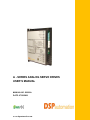
A - SERIES ANALOG SERVO DRIVES
USER’S MANUAL
MANUAL NO. 20006-A
DATE: 07/28/2009
www.dspautomation.com
Dear Reader
Thank you for choosing the DSP Automation A-Series Analog Servo Drives. This
manual will help you understand the operation of the servo drives, so you can
easily integrate them to your application. Read the manual carefully and you will
soon become familiar with all the great features of the A-Series Analog Servo
Drives. Please observe the safety rules in order to avoid hazards and product
failures.
CAUTION: Reverse power bus polarity will result catastrophic failure of the drive and
possible explosion of the bus capacitor and other components, possibly resulting serious
injury.
Warning! Failure to comply with the safety rules can result electrical hazards
leading to personal injury and/or equipment malfunction. Make sure you read
Section 1 “Safety”, before you attempt to operate the servo drives.
Copyright © 2009 DSP AUTOMATION INC.
All rights reserved. No part of this publication may be reproduced, stored, or transmitted
without the prior written permission of DSP Automation. The information in this
document is subject to change without notice
www.dspautomation.com
A-SERIES USER’S MANUAL
DOCUMENT NO. 20006-A
DSP AUTOMATION
REVISION HISTORY
Revision Release Date
Changes
20006-A
Initial Release
7/28/2009
ii
A-SERIES USER’S MANUAL
DOCUMENT NO. 20006-A
DSP AUTOMATION
TABLE OF CONTENTS
1
2
3
4
5
6
7
Safety ........................................................................................................................ 1
1.1
Safety Rules ...................................................................................................... 1
Packaging & Handling .......................................................................................... 3
2.1
Packaging .......................................................................................................... 3
2.2
Handling ............................................................................................................. 3
2.3
Repair ................................................................................................................. 3
2.4
Warranty ............................................................................................................ 4
Technical Specifications ...................................................................................... 5
3.1
Nameplate Data................................................................................................ 5
3.2
Model Number Format .................................................................................... 6
3.3
Environmental Specifications ......................................................................... 7
3.4
Mechanical Specifications .............................................................................. 7
3.5
Electrical Specifications .................................................................................. 7
3.6
Performance Specifications ............................................................................ 8
Mechanical Installation ......................................................................................... 9
4.1
Dimensions........................................................................................................ 9
4.2
Mounting .......................................................................................................... 10
4.3
Airflow............................................................................................................... 10
Electrical Installation .......................................................................................... 11
5.1
A-Series Power / Motor Connectivity .......................................................... 11
5.2
Grounding/Shielding ...................................................................................... 12
5.3
Signal Connectivity......................................................................................... 13
5.4
Digital Inputs ................................................................................................... 13
5.4.1 Digital Outputs .............................................................................................. 14
5.4.2 Analog Input/Tachometer ............................................................................. 14
5.4.3 Analog Outputs ............................................................................................. 14
5.5
Wire Specifications......................................................................................... 14
5.6
Fuses/Breakers .............................................................................................. 15
5.7
EMI/RFI Filters ................................................................................................ 15
Drive Operation .................................................................................................... 16
6.1
Configuration Jumpers J3 ............................................................................. 16
6.2
Operating Modes ............................................................................................ 17
6.3
Digital I/O Configuration ................................................................................ 17
6.4
Diagnostics ...................................................................................................... 18
6.5
Potentiometer Configuration ......................................................................... 19
6.5.1 Input Scaling ................................................................................................. 19
6.5.2 Tachometer Scaling ...................................................................................... 19
6.5.3 Compensation ............................................................................................... 19
6.5.4 Current Limit ................................................................................................ 20
6.5.5 Balance .......................................................................................................... 20
6.5.6 RMS Current ................................................................................................. 20
Appendix ................................................................................................................ 21
iii
A-SERIES USER’S MANUAL
DOCUMENT NO. 20006-A
7.1
7.2
7.3
DSP AUTOMATION
RoHS Compliance.......................................................................................... 21
UL Compliance ............................................................................................... 21
CE Compliance ............................................................................................... 21
iv
A-SERIES USER’S MANUAL
DOCUMENT NO. 20006-A
DSP AUTOMATION
LIST OF FIGURES
Figure 1: Nameplate ........................................................................................................ 5
Figure 2: A-Series Model Number Format ................................................................... 6
Figure 3: Mechanical Dimensions ................................................................................. 9
Figure 4: A-Series Drive ................................................................................................ 11
Figure 5: Grounding Points ........................................................................................... 12
Figure 6: Configuration/Diagnostics ............................................................................ 16
v
A-SERIES USER’S MANUAL
DOCUMENT NO. 20006-A
DSP AUTOMATION
LIST OF TABLES
Table 1: Environmental Specifications.......................................................................... 7
Table 2: Mechanical Specifications ............................................................................... 7
Table 3: Electrical Specifications ................................................................................... 7
Table 4: Performance Specifications ............................................................................ 8
Table 5: J1 Signal Connector ....................................................................................... 13
Table 6: Recommended Cables for A-Series Drives................................................ 15
Table 7: Configuration Jumpers J3 ............................................................................. 17
Table 8: Diagnostic Codes............................................................................................ 18
vi
A-SERIES USER’S MANUAL
DOCUMENT NO. 20006-A
DSP AUTOMATION
This page intentionally left blank
vii
A-SERIES USER’S MANUAL
DOCUMENT NO. 20006-A
1
DSP AUTOMATION
Safety
Only qualified personnel may install, adjust, and maintain the digital servo drives.
Personnel should be knowledgeable of performing tasks such as installing,
commissioning, and operating the servo system. Failure to comply with the safety
rules can result personal injury or death. Product damage is also possible.
1.1 Safety Rules
Always observe the following safety rules to avoid accidents and electrical
hazards:
•
Always keep cover of the servo drive on. Do not touch terminals for at
least 10 seconds after the power has been turned OFF. Residual voltage
in the drive’s capacitors can cause electric shock. Measure with a
multimeter the DC bus link voltage to ensure the voltage has dropped to a
safe level.
•
Always observe the national codes for proper cabinet wiring.
•
Ensure all system components are connected to low resistance earth
ground. Improper grounding can cause electric shock. Do not attempt to
change wiring while power is applied to the system. Take special care of
proper grounding when isolation transformers are being used.
•
The servo drives contain electrostatic sensitive devices. To prevent
damage, avoid contact with insulating materials, such as plastic film and
synthetic fibers. Make sure you ground yourself in order to get rid of any
possible charges.
•
Do not touch the servo drives during operation. Doing so may result in
burns due to high temperatures. These can be as high as 85°C.
•
Make sure you provide adequate cooling and/or air flow in a cabinet, in
order not to exceed the rated ambient temperature (40°C). If this cannot
be avoided then the servo drives have to be operated at less than rated
power levels in order not to exceed the maximum operating temperature
•
Electrical arcing can damage the servo drive power contacts. Never
connect or disconnect power or motor cables while the servo drive is on.
•
Read carefully the nameplate on the drive for proper voltage rating. Wrong
voltage, higher than rated, can result equipment failure and possible
explosion.
Do not operate the servo drive in environments that contain explosive
gases, corrosive acids, or any other hazardous gases and liquids. Also
•
1
A-SERIES USER’S MANUAL
DOCUMENT NO. 20006-A
•
DSP AUTOMATION
make sure solid particles (especially conductive) do not enter the air vents
of the drives
The A-Series servo drives are supposed to be used in industrial
environments. When there are used in different environments (i.e.
residential, medical equipment) additional filtering measures have to taken
to ensure acceptable EMI/RFI levels.
2
A-SERIES USER’S MANUAL
DOCUMENT NO. 20006-A
2
DSP AUTOMATION
Packaging & Handling
2.1 Packaging
The A-series servo drives are shipped in cartons with adequate cushioning
material to protect from shocks. However, it is good practice to avoid serious
shocks during storage and transportation. Cartons are not water proof and
special precautions have to be taken to prevent water/moisture from entering the
boxes. Servo drives are enclosed in anti-static bags to protect from static
charges damaging the sensitive terminals. Use proper caution when you take the
drive out of the bag. Make sure you discharge yourself or any handling tools
used.
Each servo drive box includes the following:
•
•
•
•
A-Series Drive (1)
Signal Connector (1) and crimp contacts (15). Please read wiring section
for appropriate crimping tools
Jumper contacts for configuration settings (4)
Power/Motor mating plug (on the servo drive side) (1)
For motor power or signal cables, or any other accessories please contact DSP
Automation.
2.2 Handling
Please comply with the following rules for proper equipment handling:
•
•
•
•
Avoid serious shocks such as dropping the equipment
Transport and store in the temperature range of -25°C to 60°C
Relative Humidity should be less than 95%, non-condensing
Always clean the equipment with a dry cloth and make sure no liquids or
solids enter the air vents.
2.3 Repair
Repair is done only by DSP Automation at the factory. Equipment has to be
shipped back after contacting the manufacturer. Do not open/disassemble the
product because it will void the warranty.
3
A-SERIES USER’S MANUAL
DOCUMENT NO. 20006-A
DSP AUTOMATION
2.4 Warranty
The standard equipment warranty is two years after the day of purchase. Please
contact DSP Automation for extended warranty options.
4
A-SERIES USER’S MANUAL
DOCUMENT NO. 20006-A
3
DSP AUTOMATION
Technical Specifications
3.1 Nameplate Data
Each drive has a nameplate like the one shown in Fig.1, attached on the side of
the device. The interpretation of its data is also shown in Fig. 1.
Model Number: Look at the
following section for explanation
Country of
manufacturing
Serial Number: First 4 digits show
manufacturing date mm/yy, rest 7
digits are internal to DSP Automation
Enclosure
rating
Regulatory
compliances
Rated operating voltage and
current are explicitly shown
on the nameplate
Figure 1: Nameplate
5
A-SERIES USER’S MANUAL
DOCUMENT NO. 20006-A
DSP AUTOMATION
3.2 Model Number Format
A – 180 – 8 – Cxxx
A Family
(Analog, DC Input)
Voltage Rating
80: 15 -80VDC
180: 50-180VDC
CUSTOM:
C000 – C999
N/A:
STANDARD
Current Rating (RMS)
2: 2A
12: 12A
4: 4A
15: 15A
8: 8A
Figure 2: A-Series Model Number Format
6
A-SERIES USER’S MANUAL
DOCUMENT NO. 20006-A
DSP AUTOMATION
3.3 Environmental Specifications
A-SERIES
0 oC to 40 oC (for higher ambient
temperature contact manufacturer for
derating information)
-25 oC to 60 oC
95% non-condensing
IP 20
Ambient Temperature
Storage temp
Maximum humidity
Protection level
Table 1: Environmental Specifications
3.4 Mechanical Specifications
A SERIES
Height in(mm)
Depth (incl.
connectors) in(mm)
Width in(mm)
Weight lbs (kg)
6.0 (152.4)
4.50 (114.3)
1.7(43.18)
1.0(0.45)
Table 2: Mechanical Specifications
3.5 Electrical Specifications
A SERIES
Continuous Output
Current (RMS)
Peak Output Current
Max. Peak Current Time
Bus Voltage (A-80)
Bus Voltage (A-180)
A
2
4
8
12
15
A
6
12
16
24
25
Sec
VDC
VDC
3 sec @ peak output current
15 - 80
48 - 180
Table 3: Electrical Specifications
7
A-SERIES USER’S MANUAL
DOCUMENT NO. 20006-A
DSP AUTOMATION
3.6 Performance Specifications
A SERIES
Max Current Loop BW
Max Velocity Loop BW
2.5 kHz
400Hz
PWM Frequency
Commissioning /
Diagnostics
Analog Inputs (x1)
Analog outputs (x1)
8-20kHz
Digital Inputs (x3)
Digital Outputs(x1)
Motor Feedback
Operating Modes
Motors Supported
Jumpers/Status LED
+/-10V, Differential
Current monitor, 160mV/A
4.5-30.0VDC Input Range,
Enable/Reset (1x), Limit Switches (x2)
4.5-30.0VDC/ 100mA max, Fault Output,
Open Collector (Pull-up Optional)
Tachometer: (+/-50V max.)
Torque (Current), Velocity
Brushed
Table 4: Performance Specifications
8
A-SERIES USER’S MANUAL
DOCUMENT NO. 20006-A
4
DSP AUTOMATION
Mechanical Installation
This chapter provides with instructions on how to properly mount the A-series
drives in proper equipment cabinets.
4.1 Dimensions
Figure 2 is showing the dimensions of the A-Series drives. Keep in mind that the
connectors in the front of the unit extend about 0.5inch (12.7mm).
Figure 3: Mechanical Dimensions
9
A-SERIES USER’S MANUAL
DOCUMENT NO. 20006-A
DSP AUTOMATION
4.2 Mounting
Mount the A-series drives only vertical with adequate space around them, in
order to allow proper air circulation. When you mount multiple drives next to each
other, leave at least 0.5inch (12.7mm) in between.
Mount drives in appropriate cabinets protecting from dust and liquids. Screw
down drives to the cabinet plate with two machine screws 8-32 size (M4 metric).
Make sure you use appropriate strain relief brackets for all motor, power, and
signal cables, in order to avoid problems with the control of the motors, or even
electrical hazards with the power connectors.
4.3 Airflow
Adequate airflow should exist in a cabinet in order to guarantee the ambient
temperature will not rise above the specification limits. In certain cases, it may be
necessary to mount fans with direct airflow to the drives. In those cases, mount
fans below the drives blowing directly to them.
10
A-SERIES USER’S MANUAL
DOCUMENT NO. 20006-A
5
DSP AUTOMATION
Electrical Installation
This chapter provides all the necessary information to properly wire the A-Series
analog servo drives. Figure 4 shows an A-series drive which makes clear the
connectors’ designations. Every A-Series drive has a side overlay that is pretty
much self-sufficient to wire a drive.
Make sure you properly strain relief all cables that are connected to the drives, in
order to avoid problems with the control of the motors, or even electrical hazards
with the power connectors.
J3
(internal)
v
J1
J2
STATUS LED
POTENTIOMETERS
Figure 4: A-Series Drive
5.1 A-Series Power / Motor Connectivity
The A-series drives accept DC power in order to power both motor and the drive
control electronics through a DC/DC converter. There is only one power
connector, J2, which can be seen in Figure 4. Both the DC bus and the motor are
connected to this connector. Here are the cables to connect to this motor.
•
Connect the power bus positive lead to J2-POWER VDC
11
A-SERIES USER’S MANUAL
DOCUMENT NO. 20006-A
•
•
•
DSP AUTOMATION
Connect the power bus ground (or negative) to J2-POWER GROUND
Connect the motor positive lead to J2-MOTOR +
Connect the motor negative lead to J2-MOTOR CAUTION: Reverse power bus polarity will result catastrophic failure of the
drive and possible explosion of the bus capacitor and other components, possibly
resulting serious injury.
5.2 Grounding/Shielding
Always ground A-Series drives to chassis ground. Figure 5 shows the location of
the bottom two screws used to mount the cover to the heatsink. Unscrew any of
those screws (do not take it off) and use appropriate lug wired directly to chassis
ground with wire at least of 12 AWG size. Make sure with a continuity meter that
the drive to chassis ground resistance is zero. In some cases you may have to
slightly scrape the cover with a file or a sharp object.
Figure 5: Grounding Points
Other than safety, if you do not properly ground the drive, you may experience
control issues and noise when drive is used above 80V.
Always use braid-shielded cables for the motor. If the motor cable shield is
terminated to the motor power connector and the motor is electrically connected
to the machine ground, leave the cable shield open-ended on the drive side. If
the shield is not terminated at the motor and/or the motor is electrically isolated
from the machine ground, connect the shield to the grounding lug you use to
ground the unit.
12
A-SERIES USER’S MANUAL
DOCUMENT NO. 20006-A
DSP AUTOMATION
5.3 Signal Connectivity
Connector J1 accepts all the Digital and Analog I/O Signals that control the drive.
Use braid and foil shielded cables for better performance. Table 5 lists all signals
available at J1.
Pin
#
Name
1
2
3
4
5
6
7
ANALOG INANALOG IN+
AGND
TACH +
TACH GROUND
LIMIT SW+
LIMIT SW-
8
ENABLE/RESET
9
CURRENT MONITOR
10
11
FAULT OUT
DGND
Signal
Differential Analog Input Differential Analog Input +
Analog Ground
Tachometer Input +
Tachometer Input Digital Input 1: Limit Switch +
Digital Input 2: Limit Switch Enable / Disable Servo
(Reset Faults)
Analog Output: Motor Current
Monitor
Fault Output
Digital Ground
Table 5: J1 Signal Connector
Attention!! For each motor feedback connector cable, terminate the shield
only on the motor side.
5.4 Digital Inputs
All digital inputs are referred to digital ground (Pin 11). Digital ground is
connected to the drive’s chassis ground. The inputs can accept signals in the 4.5
– 28VDC range. Any voltage in the range of 0-3VDC range or floating will be
recognized as low-level. Do not use any signal in the 3-4.5VDC range or
negative voltages.
The three inputs are:
• Pin 8: Enable / Rreset
• Pin 6: LIMIT SW+
• Pin 7: LIMIT SW-
13
A-SERIES USER’S MANUAL
DOCUMENT NO. 20006-A
DSP AUTOMATION
5.4.1 Digital Outputs
There is only one digital output, the fault output (Pin 10). This output is referred to
DGNG (Pin 11) and it is open collector with maximum rating 28V/100mA. The
manufacturer can add an internal pullup resistor to this output, if this is desired.
5.4.2 Analog Input/Tachometer
ANALOG IN (pins 1, 2) is the torque/velocity input for the drive. The maximum
operating input range is +/-10V and the input is protected up to +/-15V. When this
differential input is configured as single-ended, which is usually the case, connect
Pin1 (ANALOG IN-) to Pin 3 (AGND).
When in Velocity mode, connect the tachometer positive lead to Pin 4 (TACH+),
and the tachometer negative lead to Pin 5 (TACH GROUND). This input can
accept voltages up to +/-50V.
The impedance of the analog input is 40kOhm and the impedance of the
Tachometer input is 30kOhm.
5.4.3 Analog Outputs
There is one analog output, Pin 9 (CURRENT MONITOR). This pin outputs the
instantaneous motor current for monitoring purposes. The scale is 160mV/A. The
output impedance is 1kOhm.
5.5 Wire Specifications
Use braid-shielded cable for all motor power connections and braid/foil shielded
cable for the tachometer connection. It is strongly recommended you use
shielded cable for all control I/O cables and power input cables. Use flexible
wires (stranded) in order to make sure you don’t put excess mechanical stress on
the connectors. Please contact DSP Automation for recommended cable brands
and models.
Follow the following table for proper wire sizes based on the drive’s current
ratting
14
A-SERIES USER’S MANUAL
DOCUMENT NO. 20006-A
DSP AUTOMATION
Current
Rating (A
RMS)
Power Input
Cable
Motor Cable
2
18 AWG
18 AWG
4
16 AWG
16 AWG
8
14 AWG
14 AWG
12
12 AWG
12 AWG
15
10 AWG
10 AWG
Control I/O and
Tachometer
Cables
24AWG
Table 6: Recommended Cables for A-Series Drives
5.6 Fuses/Breakers
Every A-Series Drive needs to have appropriate fuses or breakers in the power
inputs. Please contact DSP Automation if you think you need assistance in this
area.
5.7 EMI/RFI Filters
In many applications external EMI/RFI filters may be required before the power
input of the drive(s). Please contact DSP Automation if you think you need
assistance in this area.
15
A-SERIES USER’S MANUAL
DOCUMENT NO. 20006-A
6
DSP AUTOMATION
Drive Operation
The A-Series analog drives target low cost and simple configuration applications.
The configuration of these units is done through jumpers for the digital I/O and
operating mode selection, and through potentiometers for the configuration of the
analog controller. This is a hybrid unit which has an analog controller section, but
also it has microcontroller that handles the diagnostics and several discrete
functions related to the operation of the PWM controller. The following sections
describe in detail how to configure an analog servo drive successfully.
6.1 Configuration Jumpers J3
Figure 6 shows configuration jumpers J3. This is a series of seven jumpers, but
only four of them are usable. In order to access these jumpers you need to take
the cover off, install the jumper caps (shipped with the drive), and then install the
cover again. The configuration is 2x7pins. Always install the 2-pin jumper caps
between each pair (total 7 pairs).
Jumper 1 is the first on the on the left as you see Figure 6, and jumper 7 the first
on the right.
J3: Configuration
jumpers
Figure 6: Configuration/Diagnostics
The following table lists the J3 jumpers and possible configurations
16
A-SERIES USER’S MANUAL
DOCUMENT NO. 20006-A
DSP AUTOMATION
Jumper
Jumper ON
Jumper OFF
(default)
1
N/A
N/A
2
Fault Output Active
High
Fault Output Active
Low
3
Enable Input
Active Low
Enable Input Active
High
4
Limit Switch Inputs
Active Low
Limit Switch Inputs
Active High
5
N/A
N/A
6
N/A
N/A
7
Current Mode
Velocity Mode
Table 7: Configuration Jumpers J3
6.2 Operating Modes
The A-Series analog drives can operate either in velocity or torque (current)
mode. As seen in the previous table, configuration is done through jumper J3:7.
When the jumper is off (default), then the drive is in velocity mode and requires a
tachometer. When it is on, the drive is in current mode.
When in current mode, a PI (Proportional-Integral) current controller regulates
the motor current. This controller’s gain is fixed and accommodates the majority
of applications. In those special cases where the gain is not optima, DSP
Automation gets involve in order to identify a proper current controller gain.
When in velocity mode, the current controller still exists, but with the addition of
preceding velocity controller (PI). The gain of this controller (P) is controlled with
the COMPENSATION potentiometer. The user is responsible for configuring this
gain (system tuning) for the specific application.
6.3 Digital I/O Configuration
Table 7 lists the possible DIO configurations. Use accordingly to select Active
High or Active Low Inputs/Outputs.
17
A-SERIES USER’S MANUAL
DOCUMENT NO. 20006-A
6.4
DSP AUTOMATION
Diagnostics
The servo drive diagnostics are handled by a microcontroller that outputs certain
codes according to the fault condition met. Those codes are LED flash codes by
the green LED to the left of J1. There may be up to 4 LEDs installed, but only the
rightmost one (as seen from the front) is active. The following table lists the
possible fault codes, possible cause and appropriate action to be taken.
Disable and re-enable the drive to clear any error codes.
FLASH CODES
(#of flashes)
SOLID
CONSTANT
FLASHING
1
Operational
Status
Servo ON
Servo OFF
Fault/Action
Current Surge
2
Over Voltage
3
Over
Temperature
Over RMS
Current surge over permitted range.
Check for either motor lead-lead fault or
lead-ground. If error persists contact the
manufacturer.
Bus voltage over permitted range. User’s
DC power supply must have regen
capability. If not, contact DSP Automation
for available power supplies.
Unit has reached 85 degrees C. External
air flow is required to cool the unit.
RMS preset current limit exceeded.
Adjust RMS potentiometer. If you need
more RMS current than the motor can
handle, you need a bigger motor/drive.
When Limit SW+ is activated it will
disable movement to that direction. Drive
does not fault. Controller needs to pull
motor back to the other direction.
When Limit SW- is activated it will disable
movement to that direction. Drive does
not fault. Controller needs to pull motor
back to the other direction.
4
5
Limit SW+
Activated
6
Limit SWActivated
N/A
N/A
Table 8: Diagnostic Codes
For codes 5 and 6 you do not need to disable/re-enable the drive. Pulling the
motor to the other direction and de-activating the switches will clear the fault
codes.
18
A-SERIES USER’S MANUAL
DOCUMENT NO. 20006-A
DSP AUTOMATION
6.5 Potentiometer Configuration
This section is very critical for the proper operation of the motion control system.
There are 6 potentiometers used for the proper configuration of the system.
Some expertise is needed in this area, but even for beginners, the following subsections describe in detail the configuration process.
In order to configure the 6 potentiometers, follow the same order they occur in
the next sub-sections, at least initially. You may need to adjust them in different
orders as you proceed with the configuration process.
For proper configuration, a scope is necessary. However, you will be able to
achieve an acceptable system configuration even without a scope, usually by
spending more time. The drives are preconfigured with a certain motor at the
factory, in order to provide the user with an easier starting point.
For all potentiometers, turn clockwise (CW) to increase a parameter, and turn
counter-clockwise (CCW) to decrease a parameter. Check the voltages
mentioned in the following subsections in the copper pads located directly to the
front of each potentiometer. When a resistance is mentioned this is when the
power is off and connector J1 is off.
6.5.1 Input Scaling
This input scales the system analog input to adjust the overall system gain:
•
•
Motor Amps/Input Volts when in current mode
RPM/Input Volts when in velocity mode
When in velocity mode, the system gain depends also on the tachometer scaling.
Usually you only need to adjust the input scaling and not the tachometer. The
preset setting for this parameter is 3.4KOhm.
6.5.2 Tachometer Scaling
This potentiometer sets the tachometer gain. The preset setting is 7KOhm and it
is valid for a tachometer with 7V/krpm constant. Increase gain if a tachometer
with smaller constant is used and decrease gain if larger constant.
6.5.3 Compensation
This pot sets the velocity loop proportional gain and adjusts the overall gain of
the system. Classic procedures for proportional controller tuning can be followed.
The preset setting is 720 Ohm. If you experience system vibration or bad
performance, turn this potentiometer all the way CCW, until you get a low system
gain (soft system response). Then start increasing until you get the maximum
acceptable gain.
19
A-SERIES USER’S MANUAL
DOCUMENT NO. 20006-A
DSP AUTOMATION
6.5.4 Current Limit
This potentiometer sets the peak current limit of the servo amplifier. Range is 025A. The pre-set value is 700Ohm which refers to a peak current of 12A. Adjust
accordingly for bigger or smaller peak currents. If you have a scope, you will be
able to see the maximum peak current when you change motor direction with a
step command. Just observe the current monitor output.
6.5.5 Balance
Set this potentiometer to adjust for any offset in the velocity control loop. This
should be done with the CNC (or other motion controller) connected and at 0V
output. Adjust until the motor is at standstill. This potentiometer is adjusted during
the testing procedure from mid-range to make the shaft of the testing motor
“freeze”. The setting is usually within +/- 1 turn and the measured resistance
around 28KOhm.
6.5.6 RMS Current
Turn clockwise to increase the RMS value. Range is 0-15A. This is preset for the
maximum model rating. A typical setting of 6Kohm refers to an RMS current of
6A. You can adjust this parameter by monitoring the current monitor output.
20
A-SERIES USER’S MANUAL
DOCUMENT NO. 20006-A
7
DSP AUTOMATION
Appendix
7.1 RoHS Compliance
A-Series Drives are RoHS compliant. They are in compliance with EU Directive
2002/95/EC, with respect to the following 6 substances:
1)
2)
3)
4)
5)
6)
Lead (Pb)
Cadmium (Cd)
Mercury (Hg)
Hexavalent chromium (Cr(VI))
Polybrominated biphenyls (PBB)
Polybrominated diphenyl ethers (PBDE)
7.2 UL Compliance
A-Series Drives are compliant with the following UL Directives:
• UL 508C: UL 508C describes the fulfillment by design of minimum
requirements for electrically operated power conversion equipment, such
as inverters and servo amplifiers.
• UL 840: UL 840 describes the fulfillment by design of air and insulation
creepage spacings for electrical equipment and printed circuit boards.
• UL60950-1: UL 60950 (previously UL1950) describes the Safety of
Information Technology equipment, including Electrical Business
Equipment.
7.3 CE Compliance
A-Series Drives are compliant with the following standards:
•
•
EC Directive 2004/108/EC, Electromagnetic compatibility, Used standard
EN61800 3 (07/2005)
EC Directive 2006/95/EC, Electrical devices for use in special voltage
limits, Used standard EN61800 5 1 (04/2008)
21